
Related Manuals for Gigabyte GA-8EGXDR


Summary of Contents for Gigabyte GA-8EGXDR
- Page 1 GA-8EGXDR Dual Xeon Processor Motherboard USER’ S MANUAL Dual Xeon Processor Motherboard Rev. 1001 12ME-8EGXDR-1001...
-
Page 2: Table Of Contents
Item Checklist ..................4 WARNING! ..................4 Chapter 1 Introduction ...............5 Features Summary....................5 GA-8EGXDR Motherboard Layout ..............7 Chapter 2 Hardware Installation Process ..........8 Step 1: Install the CPU (Central Processing Unit) .......... 9 Step 1-1: Installation Kit Preparation ..............9 Step 1-2: CPU Installation ................ - Page 3 Table of Content Chapter 4 Technical Reference ............54 Block Diagram ..................... 54 Chapter 5 Appendix ................ 55...
-
Page 4: Item Checklist
þ Driver CD for motherboard driver & utility þ SCSI Cable x 1 (Optional) þ GA-8EGXDR user’ s manual WARNING! Computer motherboards and expansion cards contain very delicate Integrated Circuit (IC) chips. To protect them against damage from static electricity, you should follow some precautions whenever you work on your computer. -
Page 5: Chapter 1 Introduction
Introduction Chapter 1 Introduction Features Summary Form Factor — 30.5cm x 33cm Extend ATX size form factor, 8 layers PCB. — Dual socket 603 for Intel FC-PGA Xeon processor suopprts ® 1.8 GB to 2.8GB and upper — Intel Pentium 4 Xeon 400MHz FSB ®... - Page 6 GA-8EGXDR Motherboard — System Intrution Detect — System Voltage Detect On-Board LAN — Build in Intel RC82544GC 10/100/1000 Gigabit Ethernet Chipset (Server Adapter) — Build-in Intel 82550PM 10/100 Fast Ethernet On-Board VGA — Build in ATI Rage XL VGA PCI Chipset with 8M SDRAM on board On-Board SCSI —...
-
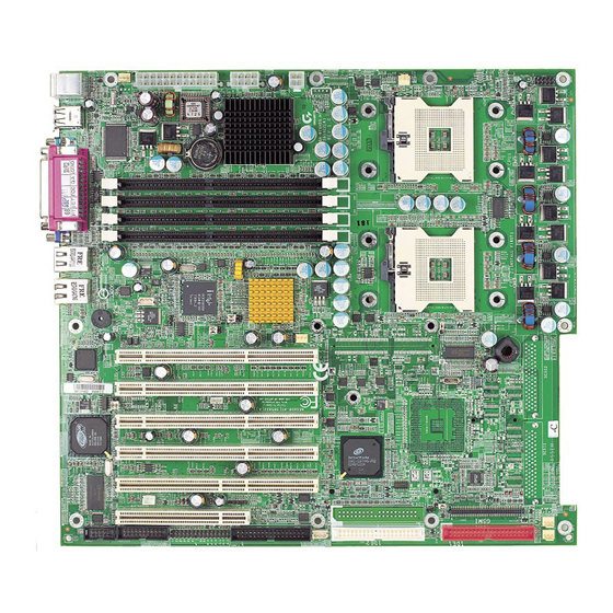
Page 7: Ga-8Egxdr Motherboard Layout
Hardw are Installation Process GA-8EGXDR Motherboard Layout USB2 COM1 LAN 1 KB_MS ATI Range 82550PM 986432DH-6 PC87417 BIOS 82544GC Battery CMIC-SL CIOBX2 CSB6 Adaptec Socket 603 Socket 603 7899W CASE OPEN SCSI W83791D CPU 2 CPU 1(Install First) GA-8EGXDR SCSI 1... -
Page 8: Chapter 2 Hardware Installation Process
GA-8EGXDR Motherboard Chapter 2 Hardware Installation Process To set up your computer, you must complete the following setups: Step 1- Install the CPU1(If you are installing one CPU ONLY) Step 2- Install memory modules Step 3- Install expansion cards Step 4- Connect cables, cabinet wires, and power supply... -
Page 9: Step 1: Install The Cpu (Central Processing Unit)
Hardw are Installation Process Step 1: Install the CPU (Central Processing Unit) Step 1-1: Installation Kit Preparation You may use the 4 screws which come with the mainboard to reinforce the support between P4 CPU heat-sink on the mainboard and chassis. Step2: Apppearance of mainboard. -
Page 10: Step 1-2: Cpu Installation
GA-8EGXDR Motherboard Step 1-2: CPU Installation Pin1 indicator CPU Top View CPU Bottom View Socket Actuation Lever Pin1 indicator 1. Pull the lever out, than lift up the Lever. 2. Locate Pin 1 in the socket and look for a (golden) cut edge on the CPU upper corner. -
Page 11: Step 1-3: Cpu Heat Sink Installation
Hardw are Installation Process Step 1-3: CPU Heat Sink Installation 1. Use qualified fan approved by Intel. 2. Heat Sink 3. First step of assembling. 4. Completive picture for Step 3. 5. Second step of assembling. 6. Completive picture for Step 5. - Page 12 GA-8EGXDR Motherboard 7. Fan assembly. 8. Hook one end of the cooler bracket to the CPU socket first. 9. Picture of device set on the motherboard. M You should apply the thermal paste to provide better heat conduction between your CPU and heatsink.
-
Page 13: Step 2: Install Memory Modules
Hardw are Installation Process Step 2: Install memory modules The motherboard has 4 dual inline memory module (DIMM) sockets. The BIOS will automatically detects memory type and size. To instal l the memory module, just push it vertically into t h e DIMM Slot. The DIMM module can only fit in one direction due to the notch. -
Page 14: Step 3: Install Expansion Cards
GA-8EGXDR Motherboard Step 3: Install expansion cards 1. Discharge any static electricity from your body before handling the sensitive board of the card. 2. Turn off and unplug your computer before removing your computer’ s chassis. Failure do so may endamger you and damage the expansion or computer. -
Page 15: Step 4: Connect Ribbon Cables, Cabinet Wires, And Power Supply
Hardw are Installation Process Step 4: Connect ribbon cables, cabinet wires, and power supply Step 4-1: I/O Back Panel Introduction u PS/2 Keyboard and PS/2 Mouse Connector PS/2 Mouse Connector ØThis connector supports standard PS/2 (6 pin Female) keyboard and mouse. PS/2 Keyboard Connector (6 pin Female) v USB2 Connector... - Page 16 GA-8EGXDR Motherboard w Parallel Port / Serial Port / VGA Port (LPT/COMA/VGA) Parallel Port (25 pin Female) ØThis connector supports 1 standard COM port ,1 Parallel port and 1 VGA port. Device like printercan be connected to Parallel port ; mouse and modem etc can be connected to Serial ports.
-
Page 17: Step 4-2: Connectors Introduction
Hardw are Installation Process Step 4-2: Connectors Introduction A) ATX1 N ) F_Panel 1 B) ATX3 O ) System FAN 1 C) ATX2 P ) System FAN 2 D) BT1 Q ) System FAN 3 E) SCSI 1 R ) System 1 (Optional) F) SCSI 2 S ) COM 2 G) FDD1... - Page 18 GA-8EGXDR Motherboard A) ATX3 (2x12 Pin ATX Power ) Ø AC power cord should onl y be connected t o your power supply unit after ATX power cable and other related devices are firmly connected to the mainboard. B) ATX1 (ATX1 Power )
- Page 19 Hardw are Installation Process T/U) CPU FAN 1/2 Connectors ØPlease note, a proper installation of the CPU cooler is essential to prevent the CPU from Sense running under abnormal condition or damaged by overheating.The CPU fan connector +12V/Control supports Max. current up to 600mA . O/P/Q) System FAN 1/2/3 Connectors Sense +12V/Control...
- Page 20 GA-8EGXDR Motherboard E/F) SCSI1/SCSI2 Connector SCSI 2 SCSI 1 I) IDE 1/ IDE 2/ IDE 3 [IDE1 / IDE2 / Connectors(Primary/Secondary)] IDE3 (Optional) IDE1 IDE2 Z) CASE OPEN G) FDD1 (Floppy Connector) Floppy Signal...
- Page 21 Hardw are Installation Process H) USB1 (Front USB Connector) ØBe careful with the polarity of the front panel USB D3+ USB connector. Check the pin assignment USB D3- while you connect the front panel USB cable. Power Please contact your nearest dealer for optional front panel USB cable.
- Page 22 GA-8EGXDR Motherboard K) F_PANEL1 (2x15 Pins connector) 1) HD+ (HDD LED) 2) HD- (HDD LED) 3) PD- (Power LED) 4) SK-(Speaker) 5) PD- (Power LED) 6) NC (Speaker) 7) PD+(Power LED) 8) NC (Speaker) 9) PW- (Power Button) 10) SK+ (Speaker)
-
Page 23: Step 4-3: Jumper Setting Introduction
Jumper Setting Step 4-3: Jumper Setting Introduction 1) JP2 8) JP9 2) JP3 9) JP10 3) JP4 10) JP11 11) J7 12) J8 Please note that the highlight white mark on the motherboard is presented as... - Page 24 GA-8EGXDR Motherboard 1) JP2 (10/100 LAN Function) G Please note that the the highlight white mark is presented as Pin 1. 1-2 close: LAN Enabled (Default) 2-3 close: LAN Disabled 2) JP3 (Onboard VGA Functon) 1-2 cl o se: VGA Enabled...
- Page 25 Jumper Setting 7) JP8 (Primary PCI-X Bus Speed Functon) 1-2 close: Conventional PCI Mode (Default) 2-3 close: PCI-X Ø Note: PCI-X - Slot 3, PCI-X - Slot 4, On board SCSI 8) JP9 (Secondary PCI-X Bus Speed Functon) 1-2 close: Conventional PCI Mode 2-3 close: PCI-X (Default) Ø...
- Page 26 GA-8EGXDR Motherboard 12) J7 (SCSI 2 On-Board Terminator Functon) Close: Enable (Default) Open: Auot...
-
Page 27: Step 4-4: Pci Slot Introduction
Hardw are Installation Process Step 4-4: PCI Slot Introduction CPU1 (INSTALL FIRST) CPU2... - Page 28 GA-8EGXDR Motherboard PCI_X_SLOT1 PCI_X_SLOT2 PCI-X 100MHz PCI-X 100MHz Supports Supports PCI_X_SLOT3 PCI_X_SLOT4 PCI 64/66MHz Supports PCI 64/66MHz Supports For ZCR Installation PCI_32_SLOT6 PCI_64_SLOT5 PCI 32/33MHz Supports PCI 64/33MHz Supports...
-
Page 29: Chapter 3 Bios Setup
BIOS Setup Chapter 3 BIOS Setup BIOS Setup is an overview of the BIOS Setup Program. The program that allows users to modify the basic system configuration. This type of information is stored in battery-backed CMOS RAM so that it retains the Setup information when the power is turned off. -
Page 30: Getting Help
GA-8EGXDR Motherboard GETTING HELP Main Menu The on-line description of the highlighted setup function is displayed at the bottom of the screen. Status Page Setup Menu / Option Page Setup Menu Press F1 to pop up a small help window that describes the appropriate keys to use and the possible selections for the highlighted item. -
Page 31: Main
BIOS Setup Main Once you enter AMI BIOS CMOS Setup Utility, the Main Menu (Figure 1) will appear on the screen. Use arrow keys to select among the items and press <Enter> to accept or enter the sub-menu. AMI EASY Setup Utility Main Adv anced Security... - Page 32 GA-8EGXDR Motherboard C Floppy Drive A/B This category identifies the type of floppy disk drive A or drive B that have been installed in the computer. No floppy driv e installed 8None 81.2MB, 3.5 in. 3.5 inch AT-ty pe high-density driv e; 1.2M by te capacity 8720K, 3.5 in.
-
Page 33: System Information
BIOS Setup 8Fast Programmed I/O Mode This field onl y show s the information of Fast Programmed I/O Mode. 832 Bit Transfer Mode Enables 32 bit access to max imize the hard disk data transfer rate. Option: On (Default Value); Off If a hard disk has not been installed select NONE and press <Enter>. -
Page 34: Advanced
GA-8EGXDR Motherboard Advanced AMI EASY Setup Utility Main Adv anced Security Boot Ex it [Setup Help] } Adv anced Configuration } Chipset Configuration } Pow er Management Configuration } Plug & Play Configuration }Peripheral Configuration F1: Help hi: Select Item... -
Page 35: Advanced Configuration
BIOS Setup Advanced Configuration AMI EASY Setup Utility Main Adv anced Security Boot Ex it Adv anced Configuration [Setup Help] S.M.A.R.T for Hard Disk [Disabled] MPS Version for O.S BootUp Num-Lock Intel Hy per Threading [Disabled] Clock Gen Spread Spectrum [Disabled] F1: Help hi: Select Item... -
Page 36: Advanced Configuration
GA-8EGXDR Motherboard C Advanced Configuration } S.M.A.R.T for Hard Disk This filed shows if the device in the specific IDE channel supports S.M.A.R.T. S.M.A.R.Tstands for Self-Monitoring Analysis and Reporting Technology. Set this option “Enable” to permit BIOS to use S.M.A.R.T. -
Page 37: Chipset Configuration
BIOS Setup Chipset Configuration AMI EASY Setup Utility Main Adv anced Security Boot Ex it Chipset Configuration [Setup Help] ECC Check Enabled Memory Scrubbing Enabled Fatal# CPU Parity Error Enabled Fatal# IMBus Bus Error Enabled Fatal# For MultiBit Error Enabled Fatal# For SingleBit Error Enabled Alert# on IMB Parity Error... - Page 38 GA-8EGXDR Motherboard } Fatal# CPU Parity Error Enables this option to report the CPU Parity Error. Enabled Enable CPU Parity Error Checking (Default Values) Disabled Disable this function. } Fatal# IMBus Bus Error Enables this option to report the IMBus Bus Error.
-
Page 39: Power Management Configuration
BIOS Setup Power Management Configuration AMI EASY Setup Utility Main Adv anced Security Boot Ex it Pow er Management Configuration [Setup Help] Soft-Off By Pow er Button Instant off Sleep Button Enabled Wake Up On Ring Enabled Sy stem After AC Back Enabled F1: Help hi: Select Item... - Page 40 GA-8EGXDR Motherboard } Wake Up On Ring Enabled Enabled Wake Up On Ring(Default Value) Disabled Disabled this function. } System After AC Back Options: Pre-State (Default Value); OFF...
-
Page 41: Plug And Play Configuration
BIOS Setup Plug and Play Configuration AMI EASY Setup Utility Main Adv anced Security Boot Ex it Plug and Play Configuration [Setup Help] PCI Slot 1/5 IRQ Priority Auto PCI Slot 2/6 IRQ Priority Auto PCI Slot 3 IRQ Priority Auto PCI Slot 4 IRQ Priority Auto... - Page 42 GA-8EGXDR Motherboard C Plug and Play Config uration This option describes the configuration of PCI bus system, or Personal Conputer Interconnect, is a system which allows I/O devices to operate at a speeds nearing the speed the CPU itself uses when communicating withits own special components.
- Page 43 BIOS Setup } IRQ 3, 4, 5, 7, 9, 10, 11, 14, 15 This option allows a user to set if let BIOS detect the IRQ events. When the BIOS detects an IRQ trigger event being actived, the system will wake up and resumes its activities. Option: PCI/PnP (Default Value);...
-
Page 44: Peripheral Configuration
GA-8EGXDR Motherboard Peripheral Configuration AMI EASY Setup Utility Main Adv anced Security Boot Ex it Peripheral Configuration [Setup Help] OnBoard IDE Both OnBoard FDC Enabled Onboard Serial Port A 3F8/COM1 Onboard Serial Port B 2F8/COM2 Onboard Parallel Port Parallel Port Mode... - Page 45 BIOS Setup } OnBoard Serial Port A This option specifies the base I/O port address of serial prot A. 3F8/COM1 Enable onboard serial port A and set I/O address to 3F8/COM1. (Default value) 2F8/COM2 Enable onboard serial port A and set I/O address to 2F8/COM2. 3E8/COM3 Enable onboard serial port A and set I/O address to 3E8/COM3.
- Page 46 GA-8EGXDR Motherboard } Parallel Port Mode This option specifies the parallel mode. Normal The normal parallel pro is used. Bi-Directional Use this setting to support bi-directional transfers on the parallel port. The parallel port can be used with devices that adhere to the enhanced Parallel Port ( EPP ) specifications.
- Page 47 BIOS Setup } Port 64/60 Emulation This option allows user to enable or disable the Port 64/60 Emulation function. Enable Enables the Port 64/60 Emulation function Disabled Disable this function. (Default Value)
-
Page 48: Security
GA-8EGXDR Motherboard Security AMI EASY Setup Utility Main Adv anced Security Boot Ex it [Setup Help] Set Superv isor Passw ord: [Enter] Set User Passw ord: [Enter] Passw ord Check [Setup] F1: Help hi: Select Item + -: Change Values... - Page 49 BIOS Setup CSet User Password You can only enter but do not have the right to change the options of the setup menus. When you select this function, the following message will appear at the center of the screen o assist you in creating a password.
-
Page 50: Boot
GA-8EGXDR Motherboard Boot AMI EASY Setup Utility Main Adv anced Security Boot Ex it [Setup Help] Boot Dev ice Priority Floppy : 1.44 MB 3 Disabled IDE-0: ST380021A F1: Help hi: Select Item + -: Change Values F5: Setup Defaults... - Page 51 BIOS Setup } The Choice for 1st Boot Device: , Removable Device (Default Value) ATAPI CDROM Hard Disk Disabled. } The Choice for 2nd Boot Device: Removable Device ATAPI CDROM (Default Value) Hard Disk Disabled.
-
Page 52: Exit
GA-8EGXDR Motherboard Exit AMI EASY Setup Utility Main Adv anced Security Boot Ex it [Setup Help] Ex it Sav ing Changes [Enter] Ex it Discarding Changes [Enter] Load Defaul Settings [Enter] Load Original Values [Enter] F1: Help hi: Select Item... - Page 53 BIOS Setup CExit Saving Changes This option allows user to exit system setup with saving the changes. Press <Enter> on this item to ask for the following confirmation message: Pressing ‘ Y’ to store all the present setting values tha user made in this time into CMOS. Therefore, whenyou boot up y our computer next time, the BIOS will re-configure your system according data in CMOS.
-
Page 54: Chapter 4 Technical Reference
GA-8EGXDR Motherboard Revision History Chapter 4 Technical Reference Block Diagram... -
Page 55: Chapter 5 Appendix
Appendix Revision History Chapter 5 Appendix Appendix A: Intel Network Driver Installation (For example: Driver CD Ver. : 1.0) Insert the driver CD-title that came with your motherboard into your CD-ROM driver, the driver CD-title will auto start and show a series of Setup Wizard dialog boxes. If not, please double click the CD-ROM device icon in "My computer", and execute the setup.exe. - Page 56 GA-8EGXDR Motherboard 3. Ready to install the program. Click "Install" to begin the installation. Starting installation 8. Installation Result. Click 7. Wizard completed. "OK" to close the window. Click "Finish".
- Page 57 Appendix Appendix B: ATI Rage XL VGA Driver Installation Insert the driver CD-title that came with your motherboard into your CD-ROM driver, the driver CD-title will auto start and show the installation guide. If not, please double click the CD-ROM device icon in "My computer", and execute the setup.exe.
- Page 58 GA-8EGXDR Motherboard Appendix C: Adaptec SCSI Driver Installation Insert the driver CD-title that came with your motherboard into your CD-ROM driver, the driver CD-title will auto start and show the installation guide. If not, please double click the CD-ROM device icon in "My computer", and execute the setup.exe.
- Page 59 Appendix Appendix D: Utilities Installation Insert the driver CD-title that came with your motherboard into your CD-ROM driver, the driver CD-title will auto start and show the installation guide. If not, please double click the CD-ROM device icon in "My computer", and execute the setup.exe. The Utilities item contains the utility of DirectX 8.1, Adabe Acrobate Reader V.5.0, and Norton Internet Security 2002 2.
- Page 60 GA-8EGXDR Motherboard Appendix G: Acronyms Acronyms Meaning ACPI Advanced Configuration and Power Interface Advanced Power Management Accelerated Graphics Port Audio Modem Riser Advanced Communications Riser BIOS Boot Specification BIOS Basic Input / Output System Central Processing Unit CMOS Complementary Metal Oxide Semiconductor...
- Page 61 Appendix Acronyms Meaning Local Area Network Logical Block Addressing Light Emitting Diode Megahertz MIDI Musical Instrument Digital Interface Memory Translator Hub Memory Protocol Translator Network Interface Card Operating System Original Equipment Manufacturer PCI A.G.P. Controller POST Power-On Self Test Peripheral Component Interconnect RIMM Rambus in-line Memory Module Special Circumstance Instructions...
- Page 62 GA-8EGXDR Motherboard Technical Support/RMA Sheet Customer/Country: Company: Phone No.: Contact Person: E-mail Add. : Model name/Lot Number: PCB revision: BIOS version: O.S./A.S.: Hardware Mfs. Model name Size: Driver/Utility: Configuration Memory Brand Video Card Audio Card CD-ROM / DVD-ROM Modem Network...
Need help?
Do you have a question about the GA-8EGXDR and is the answer not in the manual?
Questions and answers