Advertisement
Quick Links
Advertisement

Related Manuals for Suncast Free Standing Pergola


Summary of Contents for Suncast Free Standing Pergola
-
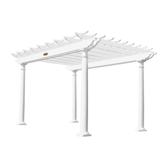
Page 1: Assembly Instructions
Includes instructions for 8' x 8', 8' x 12', 10' x 14', Numéro de controle de qualitié: 10' x 16', 12' x 16', 14' x 14', or 14' x 20' pergola Número de control de calidad: © 2011 Suncast Corporation, Batavia, IL 0660110... - Page 2 • Repair or replace broken parts immediately. Call 1-800-444-3310 for replacement parts. • Suncast is not responsible for damage caused by weather or misuse. • At regular intervals inspect your pergola to make sure that assembly integrity has been maintained.
- Page 3 Note: This product contains parts that are used in different orientations to construct the pergola. Please take note of the orientation of the parts shown throughout this instruction manual. Failure to follow instructions could result in damage to parts. Suncast is not responsible for replacing parts lost or damaged due to incorrect assembly.
- Page 4 Parts Post cover Top trim ring Top square Round trim ring post sleeve Temporary Beam Holder Vinyl column 4x4 wood post Temporary beam holder Wood block Wood peg Large base trim ring Foot bracket Optional high-wind bracket Pergola Size 8x12 10x14 10x16 12x16...
- Page 5 Parts Shade Shade trim Shade splice Rafter collar Rafter trim Rafter sleeve 7' wood rafter insert 1' Wood beam insert Beam sleeve 7' Wood beam insert Beam trim Pergola Size 8x12 10x14 10x16 12x16 14x14 14x20...
- Page 6 Hardware 5/16" x 4" Structural stainless #8 1" Screws steel white pan head screws 3/16" Concrete drill bit 2 1/2" Stainless steel white pan head screws 1/4" Wood drill bit 1/2" x 4" Concrete screws/bolts Concrete screws Washers Rafter clip Note: These pieces shown at actual size.
- Page 7 Note: Site preparation and platform construction are required for this pergola. Placing the pergola on the ground without any type of foundation is not recommended. Suncast is not responsible for replacing parts damaged or property lost due to construction without a foundation or platform.
- Page 8 Specs for post and beam layout Proper site preparation requires that the layout is square. Use the measurements on the chart provided to determine the correct spacing of the posts (A & B). The diagonal measurement (C) will ensure that the pergola is square.
- Page 9 Elevations Shade splice Rafters secured to Shade trim Hollow shades 2x6 Rafters w/ wood fillers beams w/ rafter clips Beam trim 2x8 Beams w/ wood fillers 4x4 Post 8' 9" Vinyl column 1' wood filler inside beams Foundation by others Beams (&...
- Page 10 Optional High-Wind Bracket Pre-assembly If you have chosen to purchase the high-wind Slide the high-wind bracket (C) onto the bottom of brackets (C), remove the screws in the existing the post (A), making sure that it is snug against the brackets (B).
- Page 11 Support Post Installation Using the chart on page 8, determine post layout. Mark each post location. Each mark will be the exact center of the posts. Optional high-wind bracket Standard bracket For high wind areas, position post (A) and high-wind Position post (A) and foot bracket (B) over mark and bracket (C) over mark and trace holes in bracket.
- Page 12 Standard bracket (3/16" drill bit) Optional (3/16" drill bit) high-wind bracket (1/2" drill bit) (not included) Drill holes using the 3/16" concrete drill bit (V) For high-wind areas, use a 1/2" concrete drill provided. bit (not included) to drill holes a minimum of 5" deep. Position wood posts (A) so that they are parallel Position wood post over holes and plumb using a with each other.
- Page 13 Optional bolts Use four concrete screws (Z) to secure. Tighten As an option, additional 1/2" x 4" concrete screws/ securely. Do not proceed with post covers until bolts (AA) can be installed. all wood posts are plumb and mounted securely. Optional high-wind bracket Repeat Steps 2-6 for remaining posts.
- Page 14 Post Trim Installation Slide vinyl column (D) over wood post. Fit lower Unpack post trim boxes and position trim close to portion of vinyl column over wood spacers, until each post in the order shown. cover rests securely on concrete surface. Slide the large base trim ring (E) over the top of the Slide round trim ring (F) down column until it rests column until it rests on the concrete surface.
- Page 15 Slide top trim ring (G) over column, making sure the Slide top square post sleeve (H) over wood post. rounded part is facing down and the square part is facing up. Repeat Steps 10-13 for remaining posts. This is how the top post trim should look.
- Page 16 Hook temporary beam holder (BB) on top of the Insert wood block (CC), making sure the two holes square post sleeve, facing direction of post, which in the wood block are facing upward. Insert a wood will be supporting the opposite end of the beam. peg (DD) in each hole.
-
Page 17: Beam Assembly
Beam Assembly Keep logo plate with screws. Unwrap beam sleeve (J) with the Suncast logo. Unscrew logo and remove. Set logo plate and gold screws aside to be reattached later. 6" Slide 7' wood beam insert (K) out until 6" of the filler Re-attach one side of the logo plate. - Page 18 Measure the placement of the existing screw in Slip opposite beam sleeve (J) over wood beam the logo plate and transfer the measurement to insert. Lift logo plate while sliding beam sleeve the other end of the logo plate. Insert and tighten underneath.
- Page 19 7 1/4" 6" Fasten a 1" screw (X) on the top edge of beam, Measure and mark a line 7 1/4" in from the end of 6" from the end of the beam. beam. Repeat on other end of beam. Note: Bottom Note: Top edge of beam is determined by the logo edge of beam is determined by the logo plate plate orientation.
- Page 20 Double check the orientation of the temporary beam an equal amount of beam protrudes past each post. holders and make sure they are positioned to support the beams. Ensure the Suncast logo is facing outward and place the beam (J) onto the temporary beam holders.
- Page 21 The installed beam should look like this. Position next assembled beam (J) on opposite side of post. Make sure the pre-drilled holes are facing outward and towards the bottom. Repeat steps 28-31 to install opposite beam. Remove wood pegs (DD) and slide out wood blocks (CC) to remove temporary beam holders (BB).
- Page 22 Apply cement to the flange of post cover (I). Hold the top trim ring (G) against the beams and Promptly slip post cover over the top of the top flush around the edges. Using four 2 1/2" pan head square post sleeve (H). Repeat for remaining posts. screws (Y), secure trim to beams.
- Page 23 Refer to the chart to determine rafter clip spacing. Attach a rafter clip (FF) directly over the top of the Using a tape measure and pencil, mark the location of beam splice in the center of each beam with two rafter clips.
-
Page 24: Rafter Assembly
Rafter Assembly Repeat steps 37-41 to install remaining beams and rafter clips. Slide the 7' wood rafter insert (P) out of the rafter sleeve (N) until it protrudes 42". 1 1/2" Insert a 1" screw (X) 1 1/2" from the end of the rafter Slide rafter collar (O) onto 7' wood rafter insert (P) sleeve (N). - Page 25 Repeat steps 43-46 to assemble remaining rafters. Slide rafter sleeve (N) over 7' wood rafter insert (P) until the two vinyl sleeves are touching. Insert a 1" screw (X) next to the collar. Installing the Rafters Position two step ladders next to two posts. At this point in the assembly process, all of the Place each end of a rafter (N) into the outer most posts, beams, and rafter clips should be...
- Page 26 Center the rafter on the beams, by measuring from Using four 1" screws (X), secure rafter to the rafter each end of the rafter to the outside edge of the clips. beam. Both of the measurements on each side of the beam should be equal.
- Page 27 Repeat steps 49-52 to center rafter and secure rafter to rafter clips. 4" Before moving on, measure the beams at the seam to make sure the spacing between the beams is 4". If needed, temporarily insert a 4" spacer while attaching remaining rafters.
- Page 28 Assembling the Shades Slide the shade splice (T) halfway into shade (R). Slide another shade (R) over shade splice (T), until Insert a 1" screw (X) about 1" from end of the shade. it butts against exisiting shade. Insert a 1" screw (X) about 1"...
- Page 29 Measure and mark rafters 12 1/8" from the center of Prior to fastening the shades, sight the rafters and the first shade for remaining shades. straighten shades as needed. Secure remaining shades to rafters. After positioning the shades, begin at the corner and fasten shades using 2 1/2"...
- Page 30 Installing Decorative Trim Multi-purpose cement is provided to install Apply cement to inside ring of beam trim (M). decorative trim. Promptly tap beam trim into place, so that trim is snug and level. Repeat for remaining beams. Apply cement to inside ring of rafter trim (Q). Apply cement to inside ring of shade trim (S).
- Page 31 After beam, rafter, and shade trim have been Make sure that the large base trim ring (E) is square installed, the pergola should look like this. and parallel to the beam. Secure trim with two 1" screws (X) on opposite sides of the posts. Repeat for remaining posts.
-
Page 32: Warranty
To purchase Suncast replacement parts and learn more about other Suncast products, visit us online at www.suncast.com 24 hours a day, 7 days a week, 365 days a year, or call 1-800-844-3310 Mon-Fri 6am-8pm CST.
Need help?
Do you have a question about the Free Standing Pergola and is the answer not in the manual?
Questions and answers