Table of Contents
Advertisement
Advertisement
Table of Contents

Related Manuals for Kenmore 795.58822.900


Summary of Contents for Kenmore 795.58822.900
- Page 1 SXS REFRIGERATOR REFRIGERATOR SERVICE MANUAL CAUTION BEFORE SERVICING THE UNIT, READ THE SAFETY PRECAUTIONS IN THIS MANUAL. MODELS: 795.58822.900 795.58823.900 795.58826.900 795.58829.900 Sears, Roebuck and Co., Hoffman Estates, IL60179 U.S.A. www.sears.com...
-
Page 2: Table Of Contents
CONTENTS WARNINGS AND SAFETY PRECAUTIONS ............... 1. SPECIFICATIONS ......................2. PARTS IDENTIFICATION ....................3. HOW TO INSTALL REFRIGERATOR ................4. MICOM FUNCTION ......................5. CIRCUIT ..........................6. EXPLANATION FOR MICOM CIRCUIT ................7. ICEMAKER AND DISPENSER WORKING PRINCIPLES AND REPAIR......8. -
Page 3: Warnings And Precautions For Safety
WARNINGS AND PRECAUTIONS FOR SAFETY Please observe the following safety precautions to use the 8. Do not fray, damage, run over, kink, bend, pull out, or refrigerator safely and correctly and to prevent accident or twist the power cord. injury when servicing. 9. -
Page 4: Specifications
1. SPECIFICATIONS 1-1 DISCONNECT POWER CORD BEFORE SERVICING IMPORTANT - RECONNECT ALL GROUNDING DEVICES All parts of this appliance capable of conducting electrical current are grounded. If grounding wires, screws, straps, clips, nuts or washers used to complete a path to ground are removed for service, they must be returned to their original position and properly fastened. -
Page 5: Parts Identification
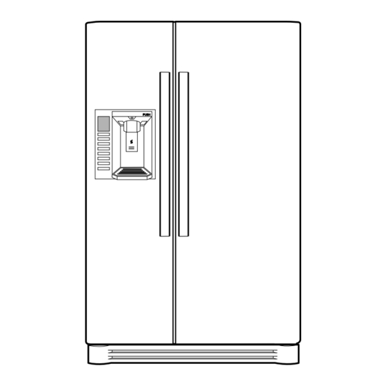
2. PARTS IDENTIFICATION PWB Cover Water Tubes PUSH Freezer Refrigerator Compartment Compartment Dairy Corner Lamp Automatic Ice maker Water Filter Shelf (steel) Door Rack Lamp Shelf Snack Drawer Door Rack Shelf (steel) Lamp Door Rack Vegetable Drawer Door Rack Vegetable Drawer Drawer (Wire/Plastic) Door Rack... -
Page 6: How To Install Refrigerator
3. HOW TO INSTALL REFRIGERATOR 1. How to Adjust Door Height of Refrigerator Make the refrigerator level first. (If the refrigerator is not installed on a flat floor, the height of freezer and refrigerator door may not be the same.) 1. - Page 7 2.Install Water Filter (Applicable to some models only) Before Installing Water Filter 1. Before installing the filter, take out the top shelf of the refrigerator after tilting it to the direction and lifting it to the direction and move it to the lower part. 2.
- Page 8 3. How to Control the Amount of Water Supplied to Icemaker. 3-1. Confirm the amount of water supplied to the icemaker. 1) Confirm the amount of water supplied to the icemaker (1) Press the button (Figure 1) to selsct the level of water (Optimum level ¡æLarge ¡æ Small.) 2) Icemaker Operation Test (Test mode) (1) Press the button (Figure 1) for more than 3 seconds and It will start the T est mode.
-
Page 9: Micom Function
4. MICOM FUNCTION 1. Monitor Panel °C °C Ultra Light °F °F Change Frz Temp Ref Temp Lock/Alarm Filter Water ULTRA ICE ICE WATER FRZ TEMP REF TEMP CHANGE LIGHT LOCK/ALARM FILTER Ultra Change Light Ref Temp Lock/Alarm Frz Temp Water Filter 1. - Page 10 1-3 Lock function (dispenser and display button lock) 1. When the refrigerator is first turned on, the buttons are not locked. The lock indicator light is turn OFF 2. To lock the display, the dispenser, and the control panel, press Lock/Alarm Lock/Alarm and hold the LOCK button for 3 seconds.
- Page 11 1-8 CONTROL OF FREEZER FAN MOTOR 1. Freezer fan motor has high and standard speeds. 2. High speed is used at power-up, for Ultra Ice, and when refrigerator is overloaded. Standard speeds is used for general purposes. 3. To improve cooling speed, the RPM of the freezer fan motor change from normal speed to high. 4.
- Page 12 1-13 Alarm for Open Door 1. This feature sounds a buzzer when the freezer or refrigerator door is not closed within 1 minute after it is opened. 2. One minute after the door is opened, the buzzer sounds three times each for 1/2 seconds. These tones repeat every 30 seconds.
- Page 13 1-16 Failure Diagnosis Error Code Diagnosis • When an error occurs, the buttons will not operate; but the tones still sound. • After the repair is made, it is necessary to replug in the refrigerator to reset to normal operation. Er FS ERROR CODE on display panel ERROR CODE...
- Page 14 1-17 TEST Mode 1. The Test mode allows checking the PCB and the function of the product as well as finding out the defective part in case of an error. 2. The test mode is operated by pressing two buttons at Display panel. 3.
-
Page 15: Circuit
5. CIRCUIT EVA-FAN CONDENSER-FAN THERMO FUSE CON10 ICE LEVER S/W CAPACITOR PART COMP’ ACCESSORIES CON2 CON2 PWB ASSEMBLY, PWB ASSEMBLY, LAMP LAMP * COMP’ ACCESSORIES * COMP’ ACCESSORIES *P.T.C OPTION *P.T.C OPTION LD, LQ COMP’ LD, LQ COMP’ EG COMP’ EG COMP’... - Page 16 CON1 CON8 CON10 CON9 - 16 -...
-
Page 17: Explanation For Micom Circuit
6.EXPLANATION FOR MICOM CIRCUIT 1. Explanation for PWB circuit 1-1. Power circuit The power circuit includes a Switched Mode Power Supply (SMPS). It consists of a rectifier (BD1 and CE1) converting AC to DC, a switch (IC2) switching the DC voltage, a transformer, and a feedback circuit (IC3 and IC4). Caution : Since high voltage (160 Vdc) is maintained at the power terminal, wait at least 3 minutes after unplugging the appliance to check the voltages to allow the current to dissipate. - Page 18 1-2. Load/dispenser operation, door opening circuit 1. LOAD DRIVING CIRCUIT Defrost Defrost Refrigerator Refrigerator Dispenser Dispenser Geared Geared Solenoid Solenoid Solenoid Solenoid Type of Load Type of Load Compressor Compressor Water Water Pilot Pilot Heater Heater LAMP LAMP Heater Heater Motor Motor Cube...
- Page 19 EVA-FAN CONDENSER-FAN CON7 (PIN5&6) CON9 (PIN4&3) CONNECTOR 7 CONNECTOR 9 F-DOOR S/W R-DOOR S/W 2*RD BO, PK PIN 5&6 PIN 3&4 Measuring part IC1 (MICOM) PIN 39, 40 Door of Freezer / Refrigerator Closing 5 V ( A - B , C - D . Switch at both ends are at Off status) Opening 0 V ( A - B , C - D .
- Page 20 1-3 Temperature sensing circuit. ITEM SENSOR LOCATION COLOR CON6 PIN7,8 2*WH CON6 PIN9,10 2*GY CON7 PIN1,2 2*WH CON7 PIN3,4 2*BO CON9 PIN5,6 2*WH CON9 PIN7,8 2*GY 1-4 Switch entry circuit The following circuit are sensing signal form the test switch , damper motor reed switch for testing and diagnosing the refrigerator.
- Page 21 1-5. Option designation circuit (model separation function) The circuit configuration is OP1 open and OP2 in short, these circuits are preset at the factory and can not be altered. Separation Connection Status Application Standard Short M/Room Open Non-M/Room Short Dispenser Open Dispenser Less 1-6.
- Page 22 The motor is driven by magnetism formed in the areas of the coils and the stator. Rotation begins when a HIGH signal is applied to MICOM Pin 33 of IC10 (TA7774P). This causes an output of HIGH and LOW signals on MICOM pins 34 and 35. Explanation) The stepping motor is driven by sending signals of 3.33 mSEC via MICOM pins 33, 34, and 35, as shown in the chart below.
-
Page 23: Fan Motor Driving Circuit
1-7. Fan motor driving circuit (freezer, mechanical area) 1. The circuit cuts all power to the fan drive IC, resulting in a standby mode. 2. This circuit changes the speed of the fan motor by varying the DC voltage between 7.5 Vdc and 16 Vdc. 3. - Page 24 T emperature compensation table at the refrigerator is as follows: Modification resistance 3.3 k 5.6 k 8.2 k 10 k 12 k 18 k 33 k 56 k 180 k Current resistance 0.5 °C 1 °C 1.5 °C 2 °C 2.5 °C 3 °C 3.5 °C...
- Page 25 2. Compensation circuit for temperature at freezer T emperature compensation in CUT JCR1 +1 °C [+1.8 °F] +2 °C [+3.6 °F] JCR2 +1 °C [+1.8 °F] JCR3 -1 °C [-1.8 °F] -2 °C [-3.6 °F] JCR4 -1 °C [-1.8 °F] Compensation Compensation T emperature compensation value...
- Page 26 1-8. Communication circuit and connection L/Wire between main PCB and display PCB The following communication circuit is used for exchanging information between the main MICOM of the Main PCB and the dedicated MICOM of the LED Display PCB. A bi-directional lead wire assembly between the two boards is required for the display to function properly. Poor communication occurs if a continuous information exchange fail to continue for more than 2 minutes between main MICOM of main PCB and LED dedicated MICOM for LED control of display PCB.
- Page 27 1) Sensor resistance characteristics table Cold storage sensor 1&2 Measuring Temperature (°C) Freezing Sensor Frost removal sensor, Outside sensor -20 °C 22.3 k 77 k -15 °C 16.9 k 60 k -15 °C 13.0 k 47.3 k -5 °C 10.1 k 38.4 k 0 °C 7.8 k...
-
Page 28: Icemaker And Dispenser Working Principles And Repair
7. ICEMAKER AND DISPENSER WORKING PRINCIPLES AND REPAIR 1. OPERATION PRINCIPLE 1-1. Operation Principle of Icemaker Power On Start Position • Adjust EJECTOR to Start Position with power on. Icemaking • Waits until water becomes cold after starting the Mode icemaking operation. - Page 29 2. ICEMAKER FUNCTIONS 2-1. Start Position 1. After POWER OFF or power outage, check the EJECTOR's position with MICOM initialization to restart. 2. How to check if it is in place: - Check HIGH/LOWsignals from HALL SENSOR in MICOM PIN. 3.
- Page 30 2-5. Function TEST 1. This is a forced operation for TEST , Service, cleaning, etc. It is operated by pressing and holding the Fill Key for 3 seconds. 2. The test works only in the Icemaking Mode. It cannot be entered from the Harvest or Fill mode. (If there is an ERROR, it can only be checked in the TEST mode.) 3.
-
Page 31: Trouble Diagnosis
8. TROUBLE DIAGNOSIS 1. TroubleShooting CLAIMS. CAUSES AND CHECK POINTS. HOW TO CHECK 1) No power at outlet. * Measuring instrument: 1. Faulty start Multi tester 2) No power on cord. Bad connection between adapter and outlet. (faulty adapter) Check the voltage. The Inner diameter of adapter. - Page 32 CLAIMS. CAUSES AND CHECK POINTS. HOW TO CHECK 2. No cooling. • Heat a clogged evaporator to 2) Refrigeration system is clogged. check it. As soon as the Moisture Residual moisture Air Blowing. Not performed. cracking sound starts, the clogged. in the evaporator.
- Page 33 CLAIMS. CAUSES AND CHECK POINTS. HOW TO CHECK 3. Refrigeration 1) Refrigerant Partly leaked. Weld joint leak. is weak. Parts leak. 2) Poor defrosting capacity. • Check visually. Drain path (pipe) clogged. Inject adiabatics into drain Inject through the hose. hole.
- Page 34 CLAIMS. CAUSES AND CHECK POINTS. HOW TO CHECK 3. Refrigeration Residual Weak heat from heater. Sheath Heater - rated. is weak. frost. Heater plate No contact to drain. Loosened stopper cord. Heater cord-L Not touching the evaporator pipe. Location of assembly (top and middle).
- Page 35 CLAIMS. CAUSES AND CHECK POINTS. HOW TO CHECK 3. Refrigeration 4) No cooling air circulation. is weak. Faulty fan motor. Fan is Fan shroud contact. - Clearance. constrained. Damping evaporator contact. Accumulated residual frost. Small cooling air Insufficient Fan overload. - Fan misuse. Bad low termperature RPM characteristics.
- Page 36 CLAIMS. CAUSES AND CHECK POINTS. HOW TO CHECK 4. Warm 1) Colgged cooling path. refrigerator Adiabatics liquid leak. compartment Foreign materials. –– Adiabatics dump liquid. temperature. 2) Food storate. Store hot food. Store too much at once. Door open. Packages block air flow. 5.
- Page 37 CLAIMS. CAUSES AND CHECK POINTS. HOW TO CHECK 6. Condensation 4) Condensation on door. and ice Condensation on the duct door. - Duct door heater is cut. formation. Condensation on the Recess Heater is cut. dispense recess. Duct door is open. / Foreign material clogging. Condensation on the Not fully filled.
- Page 38 CLAIMS. CAUSES AND CHECK POINTS. HOW TO CHECK 7. Sounds 1) Compressor compartment operating sounds. Transformer sound. Its own fault. - Core gap. Bad connection. - Correct screw connection. Drip tray vibration sound. Bad assembly. Distortion. Foreign materials inside. Back cover machine sound. Bad connection.
- Page 39 CLAIMS. CAUSES AND CHECK POINTS. HOW TO CHECK 8. Faulty lamp 1) Lamp problem. Filament blows out. (freezer and Glass is broken. refrigerator 2) Bad lamp assembly. Not inserted. compartment). Loosened by vibration. 3) Bad lamp socket. Disconnection. Bad soldering. Bad rivet contact.
- Page 40 CLAIMS. CAUSES AND CHECK POINTS. HOW TO CHECK 10. Structure, 1) Door foam. appearance, Sag. Hinge loose Bolt is loosened during and others. transportation. Not tightly fastened. Screw worn out . Weak gasket Adhesion surface. adhesion. Fixed tape. Not well fixed. Hinge interference.
-
Page 41: Troubleshooting
2. Faults 2-1. Power Problems Causes Checks Measures Remarks No power on - Power cord cut. - Check the voltage with tester. -Replace the components. outlet. - Faulty connector insertion. - Check visually. -Reconnect the connecting parts. - Faulty connection between plug - Check visually. - Page 42 2-3. Temperature Problems Causes Checks Measures Remarks High Poor cool air circulation due to faulty - Lock –– Check resistance with a - Replace fan motor. temperature fan motor. tester. in the freezer 0 : short. compartment. : cut. - Reconnect and reinsert. - Rotate rotor manually and check rotation.
- Page 43 2-4. Cooling Problems Causes Checks Measures Remarks High Refrigerant leak. Check sequence Weld the leaking part, recharge the Drier must be replaced. temperature 1. Check the welded parts of the refrigerant. in the freezer drier inlet and outlet and drier compartment.
- Page 44 Problems Causes Checks Measures Remarks High Cycle pipe is clogged. Check sequence. - Heat up compressor discharging Direr must be replaced. temperature in 1. Check temperature of condenser weld joints with touch, disconnect the freezer manually. the pipes, and check the clogging. compartment.
- Page 45 2-5. Defrosting failure Problems Causes Checks Measures Remarks No defrosting. Heater does not generate heat as 1. Check the resistance of heater. Heating wire is short and wire is cut. Seal the lead wire with the heating wire is cut or the circuit 0 : Short.
- Page 46 Problems Causes Checks Measures Remarks No defrosting Melting fuse blows. - Check melting fuse with tester. - Faullty parts: parts replacement. 1) Lead wire is cut. If 0 : OK. - Check wire color when maeasuring 2) Bad soldering. : wire is cut. resistance with a tester.
- Page 47 2-6. Icing Problems Causes Checks Measures Remarks Icing in the 1) Bad circulation of cool air. - Check the food is stored properly - Be acquainted with how to use. - Check the defrost refrigerator - Clogged intake port in the (check discharge and intake port - Sealing on connecting parts.
- Page 48 Problem Cause Check Measure Remarks Ice in the freezer 1) Bad cooling air circulation. - Check food storage conditions - Be acquainted with how to use. - Check the parts related compartment. - Intake port is clogged in the freezer visually.(Check clogging at intake - Check defrost (Check ice on the to defrosting if the...
- Page 49 2-7. Sound Problems Causes Checks Measures Remarks Hiss sound 1. Loud sound of compressor 1.1 Check the level of the 1) Maintain horizontal level. operation. refrigerator. 2) Replace bushing and seat if they 1.2 Check the bushing seat are sagged and aged. conditions (sagging and aging).
- Page 50 Problems Causes Checks Measures Remarks Vibration sound. 1. Vibration of shelves and foods in 1-1. Remove and replace the 1) Reassemble the vibrating parts Clack. the refrigerator. shelves in the refrigerator and insert foam or cushion where 2. Pipes interference and capillary 1-2.
- Page 51 Problems Causes Checks Measures Remarks Sound Popping It happens when refrigerant expands - Check the sound of refrigerant at the - Check the restrainer attached on the (almost the same at the end of capillary tube. initial installation. evaporator and capillary tube weld as animals crying - Check the sound when the refrigerator joints and attach another restrainer.
- Page 52 2-8. Odor Problems Causes Checks Measures Remarks Food Odor. Food (garlic, kimchi, etc) - Check the food is not wrapped. - Dry the deodorizer in a sunny place - Check the shelves or inner with adequate ventilation. wall are stained with food juice. - Store the food in the closed - Be sure food is securely covered container instead of vinyl wraps.
- Page 53 2-9. Micom Problems Symptom Causes Checks Measures Remarks Bad PCB All display Bad connection Bad connector Visual check on connector Reconnect electric power. LCD are off. between Main PCB connection from main connection. connector. and display circuit. PCB to display PCB. Defective PCB PCB transformer Check resistance of PCB...
- Page 54 Problems Symptom Causes Checks Measures Remarks Bad cooling. Freezer Compressor does Compressor Lead Wire Check compressor Lead Wire Reconnect Lead temperature is not start. is cut. with a tester. Wire. high. Defective compressor Measure voltage at PCB CON2 Replace relay RY1 Refer to load driving relay.
- Page 55 Problem Sympto Cause Check Measure Remarks Bad cooling Wrong Defective Step Motor Check Step Motor Check if Step Motor damper Reconnect lead Refrigerator Damper. damper motor and motor and reed switch lead wire. temperature. reed switch and lead wire are cut with a tester. wire are cut.
- Page 56 Problems Symptom Causes Checks Measures Remarks Bad defrost. Defrost is not Defrost lead wire is cut. Check if defrost lead wire is cut with a Reconnect Lead working. tester. Wire. Defective defrost driving relay. Check the voltage of CON2 (1 and 7) Replace relay (RY 7 Refer to load with a tester after pressing main and RY 3) or PCB.
- Page 57 Problems Symptom Causes Checks Measures Remarks Defective Buzzer does Trouble mode indication. Check trouble diagnosis function. Repair troubles Refer to mode display button. not sound indication in and buttons function do not operate. explanations. Door Buzzer Buzzer Defective connecting lead wire from Check lead wire associated with door Repair lead wire.
- Page 58 3. Sealed System Heavy Repair Summary Of Heavy Repair Process Contents Tools Trouble diagnosis Remove refrigerant - Cut charging pipe ends and discharge refrigerant from Filter, side cutters Residuals drier and compressor. - Use R134a oil and refrigerant for compressor and drier Pipe Cutter, Gas welder, N - Confirm N sealing and packing conditions before use.
- Page 59 3-3. Precautions During Heavy Repair Items Precautions 1. Use of tools. 1) Use special parts and tools for R134a. 2. Recovery of refrigerant. 1) Continue to recover the refrigerant for more than 5 minutes after turning the refrigerator off. 2) Install a piercing type valve on the high pressure line (drier side). Then use the appropriate recovery equipment to recover the refrigerant from the system.
- Page 60 3-4. Practical Work For Heavy Repair Items Precautions Evaporator 1. Removal of residual Low pressure side refrigerant. KEY POINT Hot Line Compressor Observe the sequence for removal of refrigerant. Drier Suction (If not, compressor oil may leak.) High pressure side Release Condenser Refrigent...
- Page 61 Items Precautions Evaporator 4. Vacuum degassing. Suction pipe Hot Line Compressor Drier Condenser pressure High Blue pressure Yellow KEY POINT - If power is applied Vaccum Pump during vacuum degassing, vacuum degassing shall be more effective. Pipe Connection - Run the compressor Connect the red hose to the high pressure side and the blue hose to the while charging the system.
- Page 62 Items Precautions Evaporator Hot Line Compressor Drier Condenser Charging Canister 4) Refrigerant Charging Charge refrigerant while operating a compressor as shown above. 5) Pinch the charging pipe with a pinch-off plier after completion of charging. 6) Braze the end of a pinched charging pipe with copper brazer and take a gas leakage test on the welded parts.
- Page 63 3-6. Brazing Reference Drawings Pipe Assembly, Hot Line (Freezer) Cooper Brazing Copper Brazing Silver Brazing Drier assembly Capi-tube Silver Brazing Pipe assembly, suction Pipe Assembly, Joint Copper Brazing Pipe assembly, Condenser Assembly, wire joint Silver Brazing Copper Brazing Copper Brazing Copper Brazing - 63 -...
- Page 64 4. HOW TO DEAL WITH CLAIMS 4-1. Sound Problems Checks and Measures Hiss sounds Explain general principles of sounds. • All refrigerators make noises when they run. The compressor and fan produce sounds. There is a fan in the freezer compartment which blows cool air to freezer and refrigerator compartments.
- Page 65 Problems Checks and Measures Sounds of water flowing Explain the flow of refrigerant. • When the refrigerator stops, the water flowing sound happens. This sound happens when the liquid or vapor refrigerant flows from the evaporator to compressor. Click sounds Explain the characteristics of moving parts.
- Page 66 4-2. Measures for Symptoms on Temperature Problems Checks and Measures Refrigeration is weak. Check temperature set in the temperature control knob. • Refrigerator is generally delivered with the button set at normal use (MID). But customer can adjust the temperature set depending on their habit and taste. If you feel the refrigeration is weak, then set the temperature control button at strong position.
- Page 67 4-3. Odor and Frost Problems Checks and Measures Odor in the refrigerator compartment. Explain the basic principles of food odor. • Each food has its own particular odor. Therefore it is impossible to prevent or avoid food odor completely when food is stored in the completely sealed refrigerator compartment.
- Page 68 4-4. Others Problems Checks and Measures The refrigerator case is hot. Explain the principles of radiator. • The radiator pipes are installed in the refrigerator case and partition plate between the refrigerator and the freezer compartment in order to prevent condensation formation.
-
Page 69: How To Disassemble And Assemble
9. HOW TO DISASSEMBLE AND ASSEMBLE (3) Disconnect upper hinge 1 from the hinge supporter 2 1. DOOR by grasping the front part of upper hinge and lifting up (Hinge Assembly, U) in arrow direction and pull 1) Remove lower cover and then disconnect water forward in arrow B direction. - Page 70 2. HANDLE To move the refrigerator through a house door, could be necessary to get off door handle. 1. Removing the door handle -Loosen the set screws with the 3/32” Allen wrench and remove the handle. Note: If the handle mounting fasteners need to be tightened or removed, use a 1/4” Allen wrench. 3.
- Page 71 4. DISPENSER 4) Loosen four screws with a phillips screwdriver and pull the funnel assembly to disconnect. 1) Disconnect funnel and button assembly by pulling down and forward. 5) The Cap Duct Assembly can be disconnected if the hold lever connecting screw is loosened with a phillips driver. 2) Remove the Display Frame moving out with both hands in one side and make the same process in the other side and pulling it forward like shows the picture.
- Page 72 - 72 -...
- Page 73 5. WATER-VALVE DISASSEMBLY METHOD - 73 -...
-
Page 74: Exploded View
#EV# 10. EXPLODED VIEW FREEZER DOOR PART 131C 606A 600A 131D 200A 131B 203A 201A 131A 614A 244A 212J 241G 241G 241E 243A -74-... - Page 75 #EV# EXPLODED VIEW REFRIGERATOR DOOR 241A 241C 230A 241B 231A 233A 212G 241H 244A 241H 212J 241H 241D 243B...
- Page 76 #EV# EXPLODED VIEW FREEZER COMPARTMENT 281A 281C 120D 406A 271B 271A 330B 902B 405G 404A 405A 332A 405D 610E 329A 149C 903E 316B 409A 301A 128C 158C 128E 128D 128F 149A 401A 281G 149B 106A 418A 136A 332B 103C 319B 136B...
- Page 77 #EV# EXPLODED VIEW REFRIGERATOR COMPARTMENT 140A 281B 281D 406A 271B 271C 621D 621C 128G 141A 611B 140B 611E 128H 610E 120B 120A 903D 610E 170A 903D 409A 604H 161A 128J 158A 128K 161B 151A 281H 611A 106A 154A 409A 128A 151B 128B 158B...
- Page 78 #EV# EXPLODED VIEW ICE & W ATER PART DISPENSER PARTS 278A 625A 616F 616G 627A 113E 282G 113F 405H 412A 619A 607A 617A 621B 621D 279A 501B 279B 281F 276B 276A 280A...
- Page 79 #EV# EXPLODED VIEW MACHINE COMPARTMENT 501F 103B 411A 309B 501A 310A 103A 501K 412D 304A 316A 410G 307A 419B 314A 314A 317A 328A 323B 318A 105A 319C 312A 329C 405F 315A 404B 305B 419A 405C 305C 319E 319A 105F 305C 305B...
- Page 80 795.58822.900 #EV# Loc No. Part No. Description Loc No. Part No. Description 103A 3650JA3032Q Handle,Rear 281G 4775JA2104A Hinge Assembly,Lower 103B 3650JA3032R Handle,Rear 281H 4775JA2113A Hinge Assembly,Lower 103C 3550JJ0073A Cover,Lower 282G ABN32648401 Cap Assembly,Duct 105A 5251JA3004A Tube Assembly,Drain 301A ADL72916201 Evaporator Assembly...
- Page 81 795.58823.900 #EV# Loc No. Part No. Description Loc No. Part No. Description 103A 3650JA3041W Handle,Rear 281G 4775JA2104A Hinge Assembly,Lower 103B 3650JA3041X Handle,Rear 281H 4775JA2113A Hinge Assembly,Lower 103C 3550JJ0073B Cover,Lower 282G ABN32648401 Cap Assembly,Duct 105A 5251JA3004A Tube Assembly,Drain 301A ADL72916201 Evaporator Assembly 105F 5070JJ3004C Skirt,Lower...
- Page 82 795.58826.900 #EV# Loc No. Part No. Description Loc No. Part No. Description 103A 3650JA3041W Handle,Rear 281G 4775JA2104A Hinge Assembly,Lower 103B 3650JA3041X Handle,Rear 281H 4775JA2113A Hinge Assembly,Lower 103C 3550JJ0073B Cover,Lower 282G ABN32648401 Cap Assembly,Duct 105A 5251JA3004A Tube Assembly,Drain 301A ADL72916201 Evaporator Assembly 105F 5070JJ3004C Skirt,Lower...
- Page 83 795.58829.900 #EV# Loc No. Part No. Description Loc No. Part No. Description 103A 3650JA3041Y Handle,Rear 281G 4775JA2104A Hinge Assembly,Lower 103B 3650JA3041Z Handle,Rear 281H 4775JA2113A Hinge Assembly,Lower 103C 3550JJ0073D Cover,Lower 282G ABN32648401 Cap Assembly,Duct 105A 5251JA3004A Tube Assembly,Drain 301A ADL72916201 Evaporator Assembly 105F 5070JJ3004C Skirt,Lower...
- Page 84 April, 2009...
Need help?
Do you have a question about the 795.58822.900 and is the answer not in the manual?
Questions and answers