Table of Contents
Advertisement
Advertisement
Table of Contents

Related Manuals for Yachting FC500


Summary of Contents for Yachting FC500
- Page 1 Operation Manual YTM-10500V1 FC500/520 Bait boat fishfinder www.goyachting.cn...
- Page 2 All right reserved! Except as expressly provided herein, no part of this manual may be copied, reproduced, republished, transm- itted or distributed for any purpose, without prior written consent of Yachting Electronic Co., Ltd. Yachting Electronic may find it necessary to change or end our policies, regulations, and special offers at any time.
-
Page 3: Table Of Contents
Content Introduction ................1 Installation................2 Packing list................2 Using the product..............5 Battery installation..............5 Sonar unit installation.............7 Install the RTS sensor to bait boat.........14 Introduction of RTS sensor ..........15 Tool list................16 RTS sensor installation method - 1........16 RTS sensor installation method - 2........27 Operation................33 Understanding the screen..........33 Keyboard instruction............34... -
Page 4: Table Of Contents
Depth Range..............42 Zoom Range..............43 Backlight................45 Contrast................46 Overlap Data..............47 Depth Alarm...............48 Fish Alarm................49 Main Battery ..............50 Boat Battery................51 Beeper................53 Units...................54 Language................55 Syetem Reset..............56 Simulator................57 Trouble Shooting..............58 Maintenance................62 Guarantee Conditions.............63 Specifications and Features............64 Contact us................66... -
Page 5: Introduction
R&D activities all the way and its products have been reputed for their cutting-edge technologies and reliable performance. FC500 / 520 is designed to be used with bait boat. We offer 12months charge-free maintenance against any damages induced by non-human factors; and damages beyond the 12 months are handled with reasonable charges based on concrete situations. -
Page 6: Installation
Installation Do not begin the installation unless you have read the manual instruction carefully, which contains information critical to the correct installation of your Fishfinder. And for any problems you meet during the installation, please contact your local dealer for help. Packing list Before you install the transducer to your bait boat, please check the packing list below, and make sure you are not missing any... - Page 7 1) A wireless remote sonar sensor 2) A control box 3) A antenna for mounting on bait boat 4) A power cable 5) A anenna-extended-cable 6) A antenna for mounting on the sonar handheld 7) A switch for On/Off controling of RTS sensor (optional) Note: the electric control &...
- Page 8 8) Toothed connector-R 9) Tooth connector-L 10) Locking bolt 11) Power Cable (optional) 12) Sonar control head 13) Plastic base The following items are also included: a) two screws (mounting the transducer) b) a copy of manual In the event that any of the items listed is found missing, call us immediately or log on to our website at www.goyachting.cn.
-
Page 9: Using The Product
Using the product FC500 / 520 is specially designed to be used with bait boat. Properly install the RTS sensor to your bait boat, powering the unit, and put the assemmed bait boat & RTS sensor into the water, then you are ready to know the bottom condition in 300m water area. -
Page 10: Battery Installation
Battery installation As shown below, FC500 / 520 is powered by 8 AA alkaline batteries. Please assmble the batteries according to the instruction figure curved on the plastic housing. instruction figure of battery installation... -
Page 11: Sonar Unit Installation
Sonar unit installation General dimension of the assemble sonar unit: 265mm 1. First, put the toothed connector-R into the right position of the base. - Page 12 connector-R 2. Put the connector-L into the left position of the base. connector-L...
- Page 13 3. Hold the sonar unit at a position, then insert and screw tighten the locking bolt. 4. Connect the power cable to the sonar unit. As instructed below, there are 2 ports on back of the sonar unit: A and B. A - is used to be compitable with wire transducer.
- Page 14 For FC500 / 520 model, you can choose using 2ways for power supplying: 1) use 8 AA Alkaline batteries Connect the power cable on the base to port B, then you are ready to use. Note: Before connecting the cable to sonar unit, please assemble the...
- Page 15 8 AA alkaline batteries in the way as instructed in page-06. Power cable being connected to Port B 2) use a battery Sometimes, you may prefer using a battery for power suppling. In the package, you can find a seperate power cable (optional), which is used to connect the sonar unit to a battery.
- Page 16 Power cable connect to a battery Note: in the power cable, there are 2 internal wire: - The red one is for positive electrode. - The black one is for negative electrode.
- Page 17 Note: when use the battery for power suppliing, we are not responsible for over-voltage or over-current failures. For presenting such possible failures happening, we suggest you using a 3Amp fuse.
- Page 18 Install the RemoteEye to bait boat The picture below is a overall installation instrution showing you the general conception to install the control & sonar system (namely RemoteEye) to the bait boat, which is just for your reference. Note: the selected bait boat here is just for your reference, the installation way may vary according to the structure of different bait boats.
- Page 19 Introduction of the RTS sensor RTS sensor indicates the whole set of electric & sonar control system . It is used to be mounted on your bait boat. 1. Control box 2. Wireless sensor 3. Antenna 4. Antenna-extended cable 5. Switch of on/off controlling for RTS (optional) 6.
-
Page 20: Tool List
to mount the antenna on your bait boat, instead of connect it directly to the control box. Thus it will be convenient for you to find enough space to place the control box at a proper position. Tool List (not included) 1) Hand drill 2) 5/32”... - Page 21 The shape of supporting plate may be different according to the shape of your bait boat. Note: the shape below is just for your reference. 2. Find a proper position and drill two holes on the top cover of your bait boat, as figured below: Note: Note: The hole...
- Page 22 3. Monut the antenna on the top cover of your bait 3. Monut the antenna on the top cover of your bait 3. Monut the antenna on the top cover of your bait boat. boat. boat. a) mount the antenna-extended cable to the top cover a) mount the antenna-extended cable to the top cover a) mount the antenna-extended cable to the top cover There are two connector of the antenna-extended cable, one is...
- Page 23 b) screw the antenna to the antenna-extended cable. b) screw the antenna to the antenna-extended cable. b) screw the antenna to the antenna-extended cable.
- Page 24 4. Mount the wireless sensor on the supporting 4. Mount the wireless sensor on the supporting 4. Mount the wireless sensor on the supporting plate, as instructed below plate, as instructed below plate, as instructed below a) drill three holes on the supporting plate. a) drill three holes on the supporting plate.
- Page 25 5. Mount supporting plate on the top cover of bait 5. Mount supporting plate on the top cover of bait 5. Mount supporting plate on the top cover of bait boat. boat. boat. Drill 4 holes on the supporting plate, and tighten the supp- Drill 4 holes on the supporting plate, and tighten the supp- Drill 4 holes on the supporting plate, and tighten the supp- orting plate on the top cover of your bait boat by screws.
- Page 26 find a proper position find a proper position find a proper position Note: It could be better to find a way to fix the control box in the Note: It could be better to find a way to fix the control box in the Note: It could be better to find a way to fix the control box in the bottom cover of your bait boat.
- Page 27 8. Connect the wireless sensor to the control box. 8. C 8. Connec 8. Connect the wireless sensor to the control box. nnect t t the wireless sensor to the control box. he wireless sensor to the control box.
- Page 28 9. connect the control box to the battery. 9. connect the control box to the battery. 9. connect the control box to the battery. connect to the battery connect to the battery connect to the battery There are 2 ways for powing the control box There are 2 ways for powing the control box There are 2 ways for powing the control box a) connect to a 9v alkaline battery...
- Page 29 bait boat all the time. Avoiding using under a low battery. bait boat all the time. Avoiding using under a low battery. bait boat all the time. Avoiding using under a low battery. Note: the range of battery monitoring is 5.2~15v. Note: the range of battery monitoring is 5.2~15v.
- Page 30 Note: sometimes you may need a switch to control on/off of Note: sometimes you may need a switch to control on/off of Note: sometimes you may need a switch to control on/off of the RTS sensor (see the “packing list-page2”). the RTS sensor (see the “packing list-page2”).
- Page 31 RemoteEye installation method - 2 RemoteEye installation method - 2 RemoteEye installation method - 2 RemoteEye installation method - 2 As the structure of bait boats is different, sometimes maybe you As the structure of bait boats is different, sometimes maybe you As the structure of bait boats is different, sometimes maybe you prefer mounting the sensor to your bait boat in other method, see prefer mounting the sensor to your bait boat in other method, see...
- Page 32 Sonar working method Sonar working method Sonar working method When sonar works, the signals are remitted in the direction as When sonar works, the signals are remitted in the direction as When sonar works, the signals are remitted in the direction as instructed below: instructed below: instructed below:...
- Page 33 hull of boat hull of boat hull of boat a) In the A mounting position, the sonar signals can be remitted a) In the A mounting position, the sonar signals can be remitted a) In the A mounting position, the sonar signals can be remitted without any obstacle in the two direction;...
- Page 34 1. Find a proper mounting position, and drill 3 holes 1. Find a proper mounting position, and drill 3 holes 1. Find a proper mounting position, and drill 3 holes on the bottom of your bait boat on the bottom of your bait boat on the bottom of your bait boat 3 holes 3 holes...
- Page 35 2. Hold the sensor calbe through the 12mm-hole 2. Hold the sensor calbe through the 12mm-hole 2. Hold the sensor calbe through the 12mm-hole 3. Fix the sensor with 2 screws 3. Fix the sensor with 2 screws 3. Fix the sensor with 2 screws Note: please spread some sealed glue on the screws before Note: Note: please spread some sealed glue on the screws before...
- Page 36 4. Spread some sealed glue to the drilled location, 4. Spread some sealed glue to the drilled location, 4. Spread some sealed glue to the drilled location, preventing water leakage from happening. preventing water leakage from happening. preventing water leakage from happening. 5.
-
Page 37: Operation
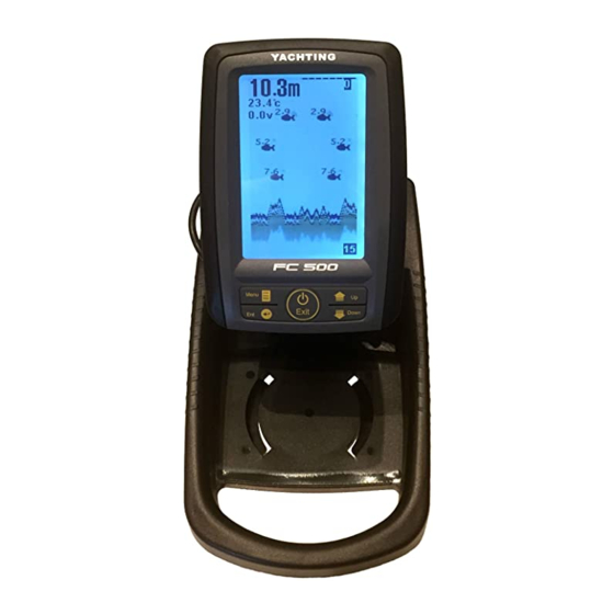
Operation Understanding the screen Water Surface Water Depth Water Temp. Depth range (Up range) Voltage Redout Fish Icon Grayline (FC520 Only) Depth range Bottom shape (Down range) This chart shows all the information that your Fishfinder display during the operation. The sonar information will firstly appears in the right side, and then scrolls across the screen from right to left. -
Page 38: Keyboard Instruction
Keyboard instruction Exit The Fishfinder sound a tone when you press the key which means the unit has accepted a command. 1. POWER & Exit Key The POWER & Exit key is used to turn the Fishfinder on or off. It is also used to exit a menu setting. - Page 39 4. Up arrow Key The Up key is used to select a certain option on a menu. In some menu option, the Up arrow key is mostly used to increase the value, such as: sensitivity value, noise reject value, depth alarm value, etc.
-
Page 40: Sensitive
1. Sonar Sensitive Sensitive determines how echoes will be displayed on the screen. Increasing the sensitivity will make you see more details on the screen. In deep water, increasing the sensitivity. whereas in shallow decreasing the sensitivity. In most situation, just setting sensitivity to “Auto” will work well. SONAR SONAR Sensitive... -
Page 41: Noise Filter
To set the Sensitive: 1) Press Menu to enter into menu setting. 2) Repeatedly Press Menu to switch to SONAR menu. 3) Use the Up / Down Arrow to select Sensitive option. 4) Press Ent to enter into setting. 5) Use the Up / Down Arrow to change the value. 6) Press Ent to confirm and exit the setting. - Page 42 In situation while water is clear, try decreasing the Noise Filter, however in situation while water is turbid, try increasing the Noise Filter will be helpful. When the water is deep enough, the high value setting may greatly affect or even hinder your Fishfinder’s performance to find the bottom.
-
Page 43: Magic Grayline
Note: For FC520, Grayline is featured by actual sonar sampling, and for FC500, the Magic Grayline is featured by calculation of the sonar program. FC520 get a little better sensitivity and Respon- siveness of sonar rutures. -
Page 44: Fish Id Sens
SONAR Sensitive Noise Filter Magic GrayLine Fish ID. Sens. Inversed 4) Press Ent to enter into setting. 5) Use the Up / Down Arrow to select the option. 6) Press Ent to confirm the setting. 7) Press Exit to exit the setting. Fish ID Sens. -
Page 45: Magic Grayline
SONAR Sensitive Noise Filter Magic GrayLine Fish ID. Sens. To set the Fish ID. Sens.: 1) Press Menu to enter into menu setting. 2) Repeatedly Press Menu to switch to SONAR menu. 3) Use the Up / Down Arrow to select Fish ID. Sens. option. 4) Press Ent to enter into setting. -
Page 46: Depth Range
2. Display Depth Range Depth Range determines in which portion the bottom will display in thescreen.( For example, if the actual depth is 10m, and the current Depth Range is 20m, then the bottom will display on 50% portion of the screen). There are total 10 levels for the depth range setting: a) With feet unit: 10, 15, 25, 35, 50, 70, 85, 100, 131, Auto b) With meter unit: 3, 5, 8, 10, 15, 20, 25, 30, 40, Auto... -
Page 47: Zoom Range
To set the Depth Range: 1) Press Menu to enter into menu setting. 2) Repeatedly Press MENU to switch to DISPLAY menu. 3) Use the Up / Down Arrow to select Depth Range option. 4) Press Ent to enter into setting. 5) Use the Up / Down Arrow to change the value. -
Page 48: Overlap Data
2) Repeatedly Press Menu to switch to DISPLAY menu. 3) Use the Up / Down Arrow to select Zoom Range Option. 4) Press Ent to enter into setting. 5) Use the Up / Down Arrow to select the option. 6) Press Ent to confirm the setting. 7) Press Exit to exit the setting. -
Page 49: Backlight
Backlight Backlight allow the unit to be used at night. There are 10 levels for you to adjust the brightness of backlight. To set the Backlight: 1) Press Menu to enter into menu setting. 2) Repeatedly Press Menu to switch to DISPLAY menu. DISPLAY Depth Range Zoom Range... -
Page 50: Contrast
Contrast Contrast can let you get a suitable display. To set the Contrast: 1) Press Menu to enter into menu setting. 2) Repeatedly Press Menu to switch to DISPLAY menu. 3) Use the Up / Down Arrow to select Contrast option. 4) Press Ent to enter into setting. -
Page 51: Overlap Data
Overlap Data On the upper left coner display, there are 3 readout: Water depth, Temperature, Voltage. Overlap Data determin which readout will be displayed. DISPLAY Depth Range Zoom Range Backlight Contrast Overlap Data Depth Temperature Voltage To set Overlap Data: 1) Press Menu to enter into menu setting. -
Page 52: Depth Alarm
3. Alarm Depth Alarm The Fishfinder sound an alarm tone when the bottom goes shallower or equal than the alarm’s setting. Note: once triggered, an alarm message will appear on the screen. You can press Menu Shallow Alarm ! key to exit the depth alarm mode, however the alarm will trigger again until your boat move to an area where the water depth is beyond the depth alarm range. -
Page 53: Fish Alarm
To set Depth Alarm: 1) Press Menu to enter into menu setting. 2) Repeatedly Press Menu to switch to ALARM menu. 3) Use the Up / Down Arrow to select Depth Alarm option. 4) Press Ent to enter into setting. 5) Use the Up / Down Arrow to change the value. -
Page 54: Main Battery
3) Use the Up / Down Arrow to select Fish Alarm option. 4) Press Ent to enter into setting. 5) Use the Up / Down Arrow to change the value. 6) Press Ent to confirm and exit the setting. Main Battery The Fishfinder sound an alarm tone when the battery strength of the sonar unit is lower then the setting. -
Page 55: Boat Battery
Note: once triggered, an alarm message will appear on the screen. The alarm will repeatedly Main VTG Low ! apprear unless the voltage of the battery is higher then the Battery Alarm setting. You can manually choose exitting the alarm mode by entering into Main Battery Alarm menu setting, and just changing the setting to a safe value will be ok. - Page 56 2) Repeatedly Press Menu to switch to ALARM menu. 3) Use the Up / Down Arrow to select Boat Battery option. 4) Press Ent to enter into setting. 5) Use the Up / Down Arrow to change the value. 6) Press Ent to confirm and exit the setting. Note: only when the RTS sensor is powered by the battery of your bait boat, then the Boat Battery Alarm can be available.
-
Page 57: Beeper
4. System Beeper Beeper is used to determin whether the fishfinder will sound a tone when a key is pressed. SYSTEM Beeper Units Language System Reset Simulator To set Beeper 1) Press Menu to enter into menu setting. 2) Repeatedly Press Menu to switch to SYSTEM menu. 3) Use the Up / Down Arrow to select Boat Battery option. -
Page 58: Units
Units Units is used to choose the depth unit and temp. unit. SYSTEM Beeper Units Language System Reset Simulator Feet / °C Feet / °F Meter / °C Meter / °F To set the units: 1) Press Menu to enter into menu setting. 2) Repeatedly Press Menu to switch to Units menu. -
Page 59: Language
Language Language is used to choose the language of menu operation. SYSTEM Beeper Units Language System Reset Simulator Deutsch English Français Italiano To set the Language: 1) Press Menu to enter into menu setting. 2) Repeatedly Press Menu to switch to SYSTEM menu. 3) Use the Up / Down Arrow to select Language option. - Page 60 System Reset System Reset is used to restore original factory setting. SYSTEM Beeper Units Language System Reset Simulator To set the System Reset: 1) Press Menu to enter into menu setting. 2) Repeatedly Press Menu to switch to SYSTEM menu. 3) Use the Up / Down Arrow to select System Reset option.
-
Page 61: Simulator
Simulator Simulator is used to let you practicing using the Fishfinder as if you were on the water. Under the simulating mode, the simulated bottom signal with fish signals will display and move across the screen, and under the simulating mode, you still could change settings to view different sonar image to have a complete understanding of your Fishfinder. -
Page 62: Trouble Shooting
Trouble shooting You are not supposed to fix the handheld or the sensor. The product contains no customizable parts. On the other hand, the waterproof performance is enabled by unique techniques, functions of which may be disabled by unauthorized disassembly. On this account, only professional maintenance personnel properly authorized by the Company are entitled to any repair necessary. - Page 63 Obstacles between the handheld and the sensor can contribute to signal loss. 2) FC500 / 520 has a detection depth ranging from 0.6 or 0.3 (0.6 for FC500; 0.3 for FC520) to 30 meters. Incorrect readings may appear in water areas with depth less than 0.6m (or 0.3m).
- Page 64 The FC500 / 520 has a depth capability from 0.3(0.6) to 30m, however due to the sonar character, the RTS sensor only can acheive the best performance in water from 1.2~30m deep.
- Page 65 b) Electrical noise nearby can interfere with the sonar, which will cause some weaker signals being eliminated. 6. The display become so cluttered that you even could not achieve a clear bottom Such cluttered display maybe caused because: a) The water is too low b) The water is too turbid c) There are so much debris in the water, 7.
-
Page 66: Maintenance
Maintenance With a view to making use of your Fishfinder, we recommend you follow the steps below and carry out maintenance. 1. For the case Cleaning the sonar unit’s outer case (except for the screen) with a cloth dipped mild detergent solution, and then wipes it dry. -
Page 67: Guarantee Conditions
Guarantee Conditions 1. We assure you this product is free from defects in materials and workmanship. The warranty coverage is One Year from the date of purchase, during which if the unit fails to perform as described in the product’s written specifications, we will repair or replace it free of charge. -
Page 68: Specifications And Features
Grayscale: 4 Levels. Adjustable backlight and contrast. Visible under sunlight. Langeuate: English / German / French / Russian. Sonar & Radio Depth Capability: FC500: 0.6~30m. FC520:0.3~30m. Wireless Operating Range: Max 300m. Sonar Frequency: 455KHZ. Sonar Beam Angle: 80deg @-10db. Radio Frequency: 433.9MHz. -
Page 69: Other Features
Power Control box Power Supply: 6~12V. Sonar Unit Power Supply: 8 × AA Alkaline Batteries. Other Features 1) Grayline features separates fish and structure from the bottom, and defines bottom hardness. 2) Zoom Capability to magnify the sonar image. 3) Built-in temp sensor in transducer. 4) Display target depth reading above each fish symbol. -
Page 70: Contact Us
Contact Us Contact Our Resource Center in any of the following days: By telephone: Monday - Friday: 8.am. to 5:30 pm. (Central Standard Time) 0086 25 84680809 Or by e-mail: Typically we respond to you in 2 business days info@goyachting.cn For direct shipping, our address is: No.508, Heyan Road, Nanjing, 210038, China... - Page 71 (Scale: 1:1; Unit:mm)
- Page 72 www.goyachting.cn...
Need help?
Do you have a question about the FC500 and is the answer not in the manual?
Questions and answers