Advertisement
Quick Links
Meijer.com
R
PB 8241
TM
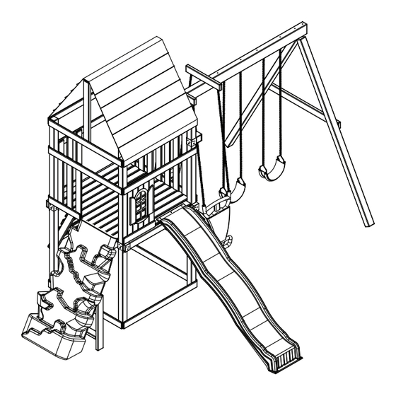
Brentwood
check out http://www.swing-n-slide.com/planupdates.htm
for updates to these instructions.
29'
27'
No. of Children: Up to 10
Min. Use Zone: 29 ' x 27 '
Set Dim. 15 'W x 13 'L x 11'H
Est. Building Time: 5-10 hr.
ASSEMBLY INSTRUCTIONS
Swing•N•Slide • 1212 Barberry Drive • Janesville, Wisconsin 53545
Visit our web site at: www.swing-n-slide.com or call us at 1-800-888-1232
Advertisement

Related Manuals for Swing-N-Slide Brentwood


Summary of Contents for Swing-N-Slide Brentwood
-
Page 1: Assembly Instructions
Min. Use Zone: 29 ' x 27 ' Set Dim. 15 'W x 13 'L x 11'H Est. Building Time: 5-10 hr. ASSEMBLY INSTRUCTIONS Swing•N•Slide • 1212 Barberry Drive • Janesville, Wisconsin 53545 Visit our web site at: www.swing-n-slide.com or call us at 1-800-888-1232... - Page 2 When the equipment is taken out of service, it must be disassembled and disposed of in such a way that no unreasonable hazards will exist at the time the set is discarded. Important! Additional Safety Instructions for all Swing-N-Slide Playground Equipment. Save this instruction sheet in the event the manufacturer needs to be contacted.
- Page 3 Meijer.com This product is intended for single family home/residential use only and not intended for use in any public setting. Placement in any public setting constitutes a misuse of this product. IMPORTANT! ADDITIONAL REQUIRED SAFETY INSTALLATION INSTRUCTIONS According to ASTM requirements, all kits must be anchored to the ground and, if the unit has a climbing rope, the rope end must be anchored to the ground. If soil conditions permit stakes to be pulled out easily, cementing into ground is necessary.
- Page 4 Meijer.com TOOLS REQUIRE HAMMER 1/2" SOCKET & WRENCH ELECTRIC DRILL SAFETY GLASSES CARPENTER'S SQUARE PHILLIPS BIT TAPE MEASURE & DUST MASK (32) 1-1/4" lag screw (4) 5/16''Hex Head Lag Screws (54) 2" lag screw (8) Tarp Washers (8) 3/4'' panhead screws (6) 5/16'' flat washers (8) 3/4'' screws (1) 3/8"...
- Page 5 (4) Anchor-It Straps (4) Anchor-It (2) Play Handles with Hardware THIS PRODUCT IS INTENDED FOR USE BY CHILDREN FROM AGES 2-10 YEARS Brentwood For Home / Residential Use ONLY Plan 1212 Barberry Drive Janesville, WI 53545 1-800-888-1232 www.swing-n-slide.com (1) Plan...
- Page 6 Meijer.com Brentwood ssembly Instructions (1) Discovery Mountain (1) Coolwave Slide with Hardware with Hardware 450 lb Weight Limit 250 lb Weight Limit (2) Reg Duty Swing Seat (1) 2 For Fun (8) Swing Hanger with Hardware with Hardware with Hardware...
- Page 7 Meijer.com Brentwood ssembly Instructions Brentwood Board List (2) 2'' x 4'' x 5'' (3) 2'' x 4'' x 17-1/4'' (Slide Stake) (2) 2'' x 4'' x 22'' (2) 2'' x 4'' x 25-1/2'' (4) 2'' x 4'' x 36'' (1) 2'' x 4'' x 47''...
- Page 8 Meijer.com Brentwood ssembly Instructions How to select the correct fastener Use these 2 pictorial guides to help select the correct fastener(s) for the lumber attachment you are making. Each diagram will highlight the correct number of fasteners to use, and where to attach them.
- Page 9 Meijer.com Brentwood ssembly Instructions ASSEMBLY INSTRUCTIONS • INSTRUCCIONES PARA ARMAR • DIRECTIVES D’ASSEMBLAGE Understanding how the Bracket System Works Example of a Shelf-Loc bracket connection. Shelf-Loc Bracket CORRECT! Wrap-Loc WRONG! Brackets ''clipped'' brackets NOT interlocked! Example of a Shelf-Loc bracket connection.
- Page 10 Meijer.com Brentwood ssembly Instructions Look for ‘’TOP’’ stamp on brackets while installing. Frame 1 onstruction DO NOT USE LAG SCREWS HERE Use Lag Screws Only Where Fig.1b Brackets Attach 3'' x 3'' x 94'' Fig.1a 2'' Lag Screws per joint...
- Page 11 Meijer.com Brentwood ssembly Instructions •WARNING• Avoid splitting your lumber by offsetting your screws at least 3/4’’ from edge. Double check to make sure structure is square Frame 1 onstruction Tip: Flex brackets to make installation of 2'' x 4'' easier Fig.
- Page 12 Meijer.com Brentwood ssembly Instructions Look for ‘’TOP’’ stamp on brackets while installing. Frame 2 onstruction Fig. 3 DO NOT USE LAG SCREWS HERE Use Lag Screws Only Where Fig. 3a Brackets Attach 3'' x 3'' x 94'' 1-1/4'' Lag Screws...
- Page 13 Meijer.com Brentwood ssembly Instructions •WARNING• Avoid splitting your Frame 2 onstruction lumber by offsetting your screws at least 3/4’’ from edge. Fig. 4 Tip: Flex brackets to make installation of 2-1/2'' screws 2'' x 4'' easier per joint 2-1/2'' screws...
- Page 14 Meijer.com Brentwood ssembly Instructions Fig. 5 2-1/2'' screws per joint Tip: Flex brackets to make installation of 2'' x 4'' easier 2-1/2'' screws per joint (2) 1-1/4'' lag screws (3) 2'' lag screws Fig. 5a per bracket (2) 1-1/4'' lag screws Approx.
- Page 15 Meijer.com Brentwood ssembly Instructions Tip: Flex brackets to make installation of Fig. 6 2'' x 4'' easier 2-1/2'' screws per joint Fig. 6a Approx. 1/4'' Fig. 6b 1-1/4'' Lag (2) 1-1/4'' lag screws (3) 2'' lag screws per bracket 2'' Lag...
- Page 16 Meijer.com Brentwood ssembly Instructions Fig. 7 Fig. 7a 2-1/2'' screws per joint 2-1/2'' screws per joint 1-1/4'' screws UNDER DECK VIEW 1-1/4'' screw 2-1/2'' screw B. Install Deck Boards 1. Install (2) 1'' x 4'' deck boards as shown in (Fig. 7).
- Page 17 Meijer.com Brentwood ssembly Instructions Fig. 8 2-1/2'' screws per joint NOTE: There must be a 1/2'' Nominal Gap between all deck boards. 2-1/2'' screw B. Install Deck Boards 1. Install (10) 1'' x 4'' deck boards to structure as shown (Fig. 8).
- Page 18 Meijer.com Brentwood ssembly Instructions Fig. 9 Fig. 9a 2-1/2'' screws 2-1/2'' per joint screws 2-1/2'' screws per joint 2-1/2'' screws per joint 2-1/2'' 2-1/2'' 2-1/2'' screws screws screws per joint 2-1/2'' screw C. Install Barrier Support Boards 1. Install (3) 1'' x 4'' lower Barrier Support Boards as shown in (Fig. 9).
- Page 19 Meijer.com Brentwood ssembly Instructions Tip: Flex brackets to make installation of 2'' x 4'' easier Fig. 10a Fig. 10 Fig. 3a Approx. 1/4'' ATTENTION: Unit has been rotated 1/4 turn Counter Clockwise for this view. 2'' Lag screw C. Install Lower Rail Boards 1.
- Page 20 Meijer.com Brentwood ssembly Instructions Fig. 11 D. Swing Beam Hole Locations 2-1/2'' 1-1/2'' 91-1/2'' 92-1/2'' 1. Install Swing Hangers into swing beam at locations shown. A-FRAME 86'' 87-1/2'' 77-3/4'' 78'' 63-3/4'' 63'' 52-1/2'' 55-1/2'' 37-1/2'' 41-1/2'' 27-1/4'' 29-1/2'' 2 FOR FUN...
- Page 21 Meijer.com Brentwood ssembly Instructions Hammer Fig. 11a 3/8'' hole T-nut t-nut Bottom Beam Clamp Use Screwdriver to aid in tightening (4) 1-1/4'' screws 1-1/4'' screw Swing Hanger E. Swing Beam Drill Locations 1. Tap T-nut into 3/8’’ hole as shown in (Fig. 11a).
- Page 22 Meijer.com Brentwood ssembly Instructions Fig. 11b Loc Nut Washer A-FRAME ATTACHES HERE 2-1/4'' Carriage Bolt 17" Fig. 11c Fig. 11f 8" min. 8" min. Fig. 11d Fig. 11e side view Drill 3/8" Holes 22" top view 2" 2" 18" E. 2 For Fun Supports 1.
- Page 23 Meijer.com Brentwood ssembly Instructions Fig. 12 3-1/2'' FACE F. A-Frame Assembly (8) 2-1/2’’ Screws 1. layout 3'' x 3-1/2’’s and 2'' x 4'' as shown in (Fig. 12). 2. Align EZ Frame Bracket with face of 3'' x 3-1/2''s. 3. Secure EZ Frame Bracket with (8)
- Page 24 Meijer.com Brentwood ssembly Instructions Fig. 13 6-1/2'' CARRIAGE BOLT WOOD LOC WASHER Washer 2-1/2'' screws Loc-Nut 2-1/2'' screw G. A-Frame Assembly cont. 1. Align EZ-Frame Bracket with carriage bolts on Swing Beam as shown in (Fig. 13). 2. Attach A-Frame beam to Swing Beam using (2) washers and (2) Loc-Nuts and 2 screws as shown in (Fig. 13).
- Page 25 Meijer.com Brentwood ssembly Instructions H. A-Frame Assembly cont. Fig. 14 1. Position Split-Brackets on 4'' x 4'' x 47-1/2'' (Fig 14). 2. With the help of others, lift A-Frame and Swing Beam Assembly and center onto unit as shown in (Fig. 14).
- Page 26 Meijer.com Brentwood ssembly Instructions 2-1/2'' screws Fig. 15 per joint Use 2-1/2'' screws to secure to 1'' x 4'' to 4'' x 4'' NOTE: There must be a 2-1/4'' Nominal Gap between rear barrier boards. Fig. 15a 1-1/4'' deck screws...
- Page 27 Meijer.com Brentwood ssembly Instructions Fig. 16 1-1/4'' deck screws per joint NOTE: There must be a 2-1/4'' Nominal Gap between side barrier boards. 1-1/4'' screw J. Install Barriers 1. Attach (3) 1'' x 4'' Barrier Boards, evenly spaced as shown in (Fig. 16).
- Page 28 Meijer.com Brentwood ssembly Instructions Fig. 17 (1) 1'' x 4'' x 7-1/16'' Window Top (Flush With Barrier (1) 1'' x 4'' x 30'' Boards) (1) 1'' x 4'' x 30'' Window Cut Fig. 17a (1) 1'' x 4'' x 30''...
- Page 29 Meijer.com Brentwood ssembly Instructions Fig. 18 2-1/2'' screws per joint 2-1/2'' screw L. Climbing Wall Support 1. Install 2'' x 4'' Climbing Wall support board as shown in (Fig. 18).
- Page 30 Meijer.com Brentwood ssembly Instructions Fig. 19 M. Climbing Wall. 1. Attach (8) 1'' x 4'' boards to (2) 2'' x 4'' boards and install on unit as shown in (Fig. 19). Note: There is a 2-3/4'' Gap between each Climbing Wall 1'' x 4'' Board.
- Page 31 Meijer.com Brentwood ssembly Instructions 2-1/2'' screws Fig. 20 2-1/2'' screws 2-1/2'' screws 1-1/2'' screws 1-1/2'' screw 2-1/2'' screw N. Tarp Support Boards 1. Install 2'' x 4'' and 1'' x 4'' tarp support boards as shown in (Fig. 20).
- Page 32 Meijer.com Brentwood ssembly Instructions Fig. 20a 3/4'' screw Fig. 20b N. Install Canopy. 1. Install canopy as shown in (Fig. 20a). Note: Make certain pleats are facing outward when Washer canopy is installed. 2. Secure canopy in six locations (Fig. 20b).
- Page 33 Meijer.com Brentwood ssembly Instructions Fig. 21 Fig. 21a 21-1/2'' 2-1/2'' screws per joint 1-1/4'' screws per joint 1-1/4'' screw 2-1/2'' screw O. Install Protective Board and Window Dressing 1. Secure protective 1'' x 4'' barrier board as shown in (Fig. 21).
- Page 34 Meijer.com Brentwood ssembly Instructions Fig. 22 1/4'' washer 1 - 3/4'' Panhead screw washer 1 - 3/4'' Panhead screw 11" 1 - 3/4'' Panhead screw Deck Surface P. Safety Handles. 1. Mount (2) safety handles in the Climbing Wall and Lookout Mountain openings, approximately 11'' above the deck surface (Fig.
- Page 35 Meijer.com Brentwood ssembly Instructions Fig. 23a Fig. 23 1-1/4'' screws UNDER DECK VIEW 1-1/4'' screw 1'' Truss Screw Use truss head screws to to secure slide to deck. Fig. 23b R. Slide Installation. 1. Attach Deck Support as shown in (Fig. 23).
- Page 36 Meijer.com Brentwood ssembly Instructions Fig. 24a Fig. 24 1-1/2" hole locations 15-1/2'' brace dig (2) 12" deep holes (2) 2-1/2'' stake 2'' x 4'' x 17-1/4'' screws per joint 12" Note: If stakes are not close enough to the wall to be secured, dig out the area around the stake(s) and reposition them until the wall and stakes meet.
- Page 37 Meijer.com Brentwood ssembly Instructions Fig. 24b four (4) 1" trusshead screws T. Lookout Mountain Attachment: Reposition the wall in the opening of the climbing unit. Center the top of the wall in the opening of the unit. The edge of the wall should be firmly positioned against the climbing unit and the stakes should be inside the base of the wall.
- Page 38 Meijer.com Brentwood ssembly Instructions Fig. 25 (2) 2-1/2'' screws Fig. 25a Bolt Cover Chain goes through here •WARNING• Do NOT Put Chain Here 5/16" Flat Washer 5/16" Flat Washer Hex Bolt 5/16 x 6-1/4" 5/16'' 5/16" Loc Washer Loc Nut...
-
Page 39: Steering Wheel
Meijer.com Brentwood ssembly Instructions Steering Wheel V. Steering Wheel Installation. Fig. 25b 1. Choose a desired location for the steering wheel and drill a 3/8" diameter hole through the lumber. NOTE: If lumber is greater than 2" in depth, you will need to... - Page 40 Meijer.com Questions???... Call our Customer Service Department at 1-800-888-1232 © PlayCore Inc. 2010 Printed In USA LA 6113...
Need help?
Do you have a question about the Brentwood and is the answer not in the manual?
Questions and answers