Table of Contents
Advertisement
Quick Links
Alpine
PROJECT 611& 612
check out http://www.swing-n-slide.com/planupdates.htm
ASSEMBLY INSTRUCTIONS
Swing•N•Slide • 1212 Barberry Drive • Janesville, Wisconsin 53545
Visit our web site at: www.swing-n-slide.com or call us at 1-800-888-1232
for updates to these instructions.
Return to Swing-N-Slide
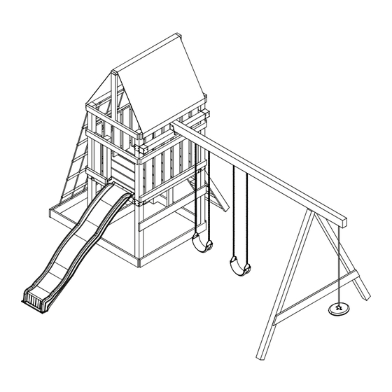
Alpine Custom Swing Set
Kit product page
TM
28.5'
No. of Children: Up to 11
Min. Use Zone: 28-1/2' x 30-1/2'
Set Dim. 13'W x 18-1/2'L x 11'H
Est. Building Time: 4-8 hr.
Meijer.com
NE 5007
30.5'
Advertisement
Table of Contents

Related Manuals for Swing-N-Slide Alpine 611


Summary of Contents for Swing-N-Slide Alpine 611
- Page 1 Meijer.com NE 5007 Return to Swing-N-Slide Alpine Custom Swing Set Alpine Kit product page PROJECT 611& 612 check out http://www.swing-n-slide.com/planupdates.htm for updates to these instructions. 28.5' 30.5' No. of Children: Up to 11 Min. Use Zone: 28-1/2' x 30-1/2' Set Dim. 13'W x 18-1/2'L x 11'H Est.
- Page 2 Meijer.com Safety Checklist for Swing-N-Slide Accessories Observing the following statements and warnings reduces the likelihood of serious or fatal injury Installation Safety – Have You: Consulted the assembly instructions supplied with your particular model? Noted this accessory is to be used only on Swing•N•Slide approved designs? (Do not alter its design or add/remove components.) Made sure all hardware is tightened securely? (Supplied bolt covers must also be fastened securely.) Using a hacksaw, cut off all protruding threaded ends of bolts and other fasteners and remove any sharp edges with a metal file as needed?
- Page 3 Meijer.com SAFETY INSTRUCTIONS INSTRUCCIONES DE SEGURIDAD IMPORTANT! INSTRUCTIONS CONCERNANT LA SÉCURITÉ This product is intended for single family residential use only and not intended for use in any public setting. Placement in any public setting constitutes a misuse of this product. REQUIRED SAFETY INSTALLATION INSTRUCTIONS •...
- Page 4 Meijer.com TOOLS REQUIRED HAMMER CIRCULAR SAW 1/2" SOCKET & WRENCH ELECTRIC DRILL SAFETY GLASSES CARPENTER'S SQUARE PHILLIPS BIT 3/8" DRILL BIT (6'' Min.) TAPE MEASURE & DUST MASK (2) 1-3/4'' panhead screws (2) 5/16'' flat washers (6) T- nuts (2) 1/2'' panhead screws (108) 2"...
- Page 5 Note: (5 Left, 5 Right) (1) Multicolor Tarp (4) Swing Hangers (2) Safety Handles (2) Swing Seats weight limit: 115 lbs. THIS PRODUCT IS Alpine INTENDED FOR USE BY CHILDREN FROM AGES 2-10 YEARS Plan For Home / Residential Use ONLY...
- Page 6 Meijer.com ALPINE REQUIRED HARDWARE (Not Included) (287) 2-1/2'' screws (56) 2'' screws (64) 1-1/4'' screws...
- Page 7 Meijer.com ALPINE...
- Page 8 How to select the correct fastener Meijer.com Use these 3 pictorial guides to help select the correct fastener(s) for the lumber attachment you are making. Each diagram will highlight the correct number of fasteners to use, and where to attach them. 5/4'' x 6'' to 4'' x 4'' 2-1/2'' screws or nails Apply the 2-1/2"...
- Page 9 Understanding how the Bracket System Works Meijer.com Example of a Shelf-Loc bracket connection. Shelf-Loc Bracket CORRECT! Wrap-Loc WRONG! Brackets ''clipped'' brackets NOT interlocked! Example of a Cup-Loc bracket connection. Top of bracket Look for ''TOP'' stamp on bracket for correct orientation. Wrap-Loc Introduction to the Bracket system 1.
- Page 10 Meijer.com 4'' x 4'' x 96'' REMEMBER: Brackets are inter-locking. Cup-loc will clip and secure into the Wrap-Loc as shown below. Fig. 1 Repeat 4x 2'' lag screws A. Frame Construction 1. Measure and position brackets on (4) 4'' x 4'' x 96’’ as shown in (Fig.1). 43-1/4'' 2'' Lag screw (4 each bracket)
- Page 11 Meijer.com Wrap-Loc opening must be positioned as shown on in these locations below Fig. 2 for later use. (See page 24) GAP (this side) lag screw to hold in place (back) Fig. 2a Look for ‘’TOP’’ Use a 2’’ lag screw stamp on brackets to hold bracket in while installing.
- Page 12 Meijer.com A. Frame Construction (cont.) (3) 2-1/2'' screws/ nails 3. Install upper 2'' x 4'' boards. Edges are to be flush with 4'' x 4’’s. Fig. 3 2-1/2'' screws/nails (4) 2-1/2'' screws/nails (1) Lag Screw (4) 2-1/2'' screws/nails (1) Lag Screw A.
- Page 13 Meijer.com Fig. 4 (3) 2-1/2'' screws/nails A. Frame Construction (cont.) 5. Attach upper 2'' x 4'' as shown in (Fig. 4). Edges are to be flush with 4’’ x 4’’s. (4) 2-1/2'' screws/nails (1) Lag Screw A. Frame Construction (cont.) 2'' Lag screw 6.
- Page 14 Meijer.com Fig. 5 A. Frame Construction (cont.) 7. Secure upper 2'' x 4'' and lower 5/4'' boards to Frame 2 as shown in (Fig. 5). Edges are to be flush with 4’’ x 4’’s. (3) 2-1/2'' screws/nails Double check to make sure structure is square Fig.
- Page 15 Meijer.com Fig. 7 B. Center Support Beam 1. Construct center support beam following the instructions in (Fig. 7). Center Support Beam Fig. 8 (2) 2-1/2'' screws/nails (each side) Center 2-1/2'' screws/nails (each side) B. Center Support Beam cont. 2. Secure center support beam to structure as 2-1/2'' or 10D shown in (Fig.
- Page 16 Meijer.com Fig. 9 2-1/2'' screws/nails (2 per joint) 2-1/2'' or 10D screw/nail C. Install Deck Boards 1. Install 5/4'' deck boards to structure as shown (Fig. 9). 2. Use two 2-1/2'' screws/nails at center and each end of deck boards. Note: Screws/Nails at center will attach to center support.
- Page 17 Meijer.com Fig. 10 D. Install 4x4 Rail Supports 1. Install (2) Cup Loc as shown in (Fig.10), (Fig 10a). 2. Install (2) 4'' x 4'' x 29-3/4'' as shown in (Fig. 11) and (Fig. 11a). Install Cup Loc using (4) 2'' lag screws 2'' Lag screw Fig.
- Page 18 Meijer.com E. Install Upper Rail Boards Fig. 12 1. Install upper 2'' x 4'' rail boards as shown in (Fig 12). 30’’ above the deck as shown in (Fig 12). Note: Measure from Top of 5/4'' board to top of 2'' x 4'' rail board.
- Page 19 Meijer.com Fig. 14 31-3/4'' 2-1/2'' screws/nails bottom of base G. Install Protective Barrier Board 1. Secure protective 5/4'' barrier board as shown in (Fig 14). 2-1/2'' or 10D screw/nail...
- Page 20 Meijer.com Fig. 15a Fig. 15 2'' Lag screw Tip: Flex brackets to make installation of 4'' x 4'' easier H. Install Accessory Brackets 1. Secure Shelf-Loc brackets onto Wrap-Loc as shown in (Fig. 15), (Fig. 15a), (Fig. 16). Fig. 16 Approx.
- Page 21 Meijer.com Fig. 17 Fig. 17a 2'' Lag screw I. Install Accessory 4x4 1. Work 4'' x 4'' into brackets as shown in (Fig. 17). 2. Secure brackets (Fig. 17a).
- Page 22 Meijer.com Optional Laminated Beam Fig. 18 NOTE: Lay the lumber on a flat surface before beginning laminated beam assembly. 24" NOTE: Attach one end of the beam with three 2-1/2'' screws. Secure boards and attach the other end with three 2-1/2'' screws. This will insure that your boards will stay aligned throughout the remainder of the beam assembly.
- Page 23 Meijer.com Fig. 19 J. Swing Beam Drill Locations 1. Use a 3/8'' drill bit to drill a 3/8’’ hole through the beam at each location shown in (Fig. 19) 2. Tap T-nut into swing beam at locations shown. TOP VIEW Drill 3/8'' Hole 3-1/2''...
- Page 24 Meijer.com Fig. 19a Hammer T-nut t-nut 3/8'' hole Bottom Beam Clamp Use Screwdriver to aid in tightening or 1-1/2'' nails (4) 1-1/4'' screws Swing Hanger J. Swing Beam Drill Locations 1. Tap T-nut into 3/8’’ hole as shown in (Fig. 19a) Note: If using Laminated Swing Beam, make sure t-nut teeth do not fall between seams of 2'' x 6''s.
- Page 25 Meijer.com Fig. 20 Fig. XX L. A-Frame Assembly 1. layout 4'' x 4''s as shown (8) 2-1/2 Screws/nails in (Fig. 20) 2. Align EZ Frame Bracket with face of 4'' x 4''s. 3. Secure EZ Frame Bracket with (8) 2-1/2'' screws /nails to 4'' x 4''s making sure they are flush with each other.
- Page 26 Meijer.com Fig. 23 T-nut 86-1/2'' to ground Washer 2-1/2'' screws/nails Hex Bolt 2-1/2'' or 10D screw/nail L. A-Frame Assembly cont. 1. Attach A-Frame beam to Swing Beam using (2) hex bolts and 4 screws/nails. 2. Tighten hex bolt to flush with top of T-nut. Repeat on other bracket. Note: If using Laminated Swing Beam, make sure t-nut teeth do not fall between seams of 2'' x 6''s.
- Page 27 Meijer.com Fig. 24 L. A-Frame Assembly cont. 1. Position Split-Brackets on 4'' x 4'' x 55'' (Fig 24). 2. With the help of others, lift A-Frame and Swing Beam Assembly and center onto unit as shown in (Fig. 24) 3. Secure as shown in (Fig 24a). Fig.
- Page 28 Meijer.com (2) 2'' screws/nails 2 per joint, top, bottom Fig. 25 Use 2-1/2'' screws to secure to 5/4'' x 6'' to 4'' x 4'' L. Barrier Boards 1. Install 5/4'' x 48'' barrier boards evenly spaced in the opening. (2) 2'' screws/nails 2 per joint, top, bottom 2'' or 8D screw/nail...
- Page 29 Meijer.com 2-1/2'' screws/nails Fig. 27 M. Roof Support. 1. Install 2'' x 4'' boards as shown. 2-1/2'' screws/nails 2-1/2'' screws/nails 2-1/2'' screws/nails 2'' or 8D screw/nail Fig. 28 Fig. 28a 1-1/4'' screw N. Install Tarp. 1. Install tarp as shown in (Fig. 28a) 2.
- Page 30 Meijer.com (see page 38 for Climbing Rock Wall Front Opening Option #2.) Front Opening Option #1 (Front) 23 1/4 2'' x 4'' x 62-1/2'' 2'' x 4'' x 62-1/2'' Fig. 29 (Right Side Rail) (Left Side Rail) (1) 2'' x 4'' x 23-1/4'' (1) 2'' x 4'' x 23-1/4'' (4) 2'' x 4'' x 20-1/4'' (2) 2-1/2'' Screws/Nails...
- Page 31 Meijer.com Fig. 32 P. Safety Handles. 1. Mount safety handles in the ladder opening approximately 11'' above the deck surface (Fig. 32). 11" 1/4'' washer 1 - 3/4 Panhead screw Fig. 33 1'' Truss Screw Use truss head screws to to secure slide to deck.
- Page 32 Meijer.com Fig. 34 R. Final Assembly. Hold the swing seat vertically and insert uncoated chains through the channels on the bottom of the swing seat. Note: A coat hanger may be used to help pull chain through the swing seat. One full link should show at each end of the seat (Fig.
- Page 33 Anchor-It Meijer.com (Purchased Separately) Fig. 38 Flat Washer metal strap 1-1/2" lag bolt Anchor-It stake S. Anchor-It Installation (optional). Instructions for Anchoring Swing•N•Slide Activity Centers 1. Determine the final location of your activity center. 2. Place the Anchor-It stakes adjacent to the base and near the corners of your activity center (at the bottom of the legs on swing sets) and twist the auger-style stakes into the ground until only the loop is exposed.
- Page 34 Meijer.com SIDE MOUNTING OPTION 1 Cargo Net Cargo Net Fig. 2 10” 10” 10” 6-1/2” LUMBER REQUIRED (sold separately) DESCRIPTION 5/4" x 6" x 10' INSTRUCTIONS 1. Cut one 5/4" x 6" x 72-3/4". Cut one 5/4" x 6" x 40" and 42-1/2". Cut remaining 5/4"...
- Page 35 Meijer.com PROJECT 612 ONLY (see page 32 for Ladder Assembly Front Opening Option #1.) Front Opening Option # 2 Fig. 39a Fig. 39 2-1/2'' screws/nails (Underneath) 2-1/2'' screws/nails (Per joint) 2-1/2'' screws/nails 3-3/8'' 23-1/4'' (Per joint) N N O O T T E E : : 2-1/2'' screw or nail 4' Climbing Rock Wall will require m m i i n n .
- Page 36 Meijer.com Questions???... Call our Customer Service Department at 1-800-888-1232 © PlayCore Inc. 2007 Printed In USA LA 5615...
Need help?
Do you have a question about the Alpine 611 and is the answer not in the manual?
Questions and answers