
Related Manuals for Rockford Fosgate Prime R250-4


Summary of Contents for Rockford Fosgate Prime R250-4
- Page 1 4CH AMPLIFIERS R250-4 Birth Date: Total RMS Power Serial Number: Date of Purchase: Installation & Operation...
- Page 2 fire and/or possible injury. ©2011 Rockford Corporation. All Rights Reversed. ROCKFORD FOSGATE associated logos where applicable are registered trademarks of Rockford Corporation in the United States and/or other countries. All other trademarks are the property of their respective owners. Specifications subject to change without notice.
- Page 3 Dimensions (LxWxH) 11.6” x 7.7” x 2.4” (29.4cm x 19.6cm x 6.1cm) CEA 2006 Power ratings on Rockford Fosgate amplifiers conform to CEA-2006 industry standards. These guidelines mean your amplifier’s output power ratings are REAL POWER numbers, not inflated marketing ratings.
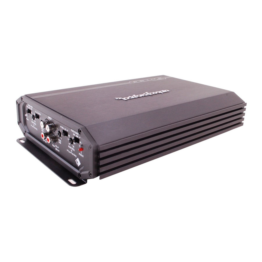
- Page 4 Gain Control The input gain control is preset to match the output of most source units. Power LED FRONT POWER GAIN Power LED illuminates blue when the unit is turned on. LEFT FRONT RIGHT RCA Input Jacks The industry standard RCA jacks provide an easy connection for signal level input.
- Page 5 Crossover Switch Selectable switch for 80Hz High-Pass (HP),All Pass (AP), or Low-Pass (LP) operation. Variable Crossover Is a built-in 12dB/octave Butterworth filter with a crossover point variable from 50Hz to 250Hz. Protect LED Protect LED illuminates red if a short circuit or to low of REAR PROTECT an impedance is detected at the speaker connections.
-
Page 6: Installation Considerations
Authorized signal or power loss. Rockford Fosgate Dealer for installation. 6. Think before you drill! Be careful not to cut or drill into gas tanks, fuel lines, brake or hydraulic lines, vacuum lines or electrical wiring when... - Page 7 Before installation, disconnect the battery neg- 7. Securely mount the amplifier to the vehicle or amp rack. Be careful not ative (-) terminal to prevent damage to the unit, to mount the amplifier on cardboard or plastic panels. Doing so may fire and/or possible injury.
-
Page 8: Channel Stereo
4-Channel Stereo illus.-2.1... - Page 9 3-Channel (2ch Stereo & 1ch Mono *bridged illus.-2.2...
-
Page 10: Adjusting Gain
Adjusting Gain Punch Bass This works along with the crossover switch on the amplifier. When set to 1. Turn amplifier gains to minimum (counter-clockwise). Low-Pass (LP) operation, this is a variable Bass Boost. Set this to your personal preference while listening to the system. 2. -
Page 11: Troubleshooting
Troubleshooting Step 5. Check Amplifier if you experience excess Engine Noise. NOTE: If you are having problems after installation follow the Trouble- 1. Route all signal carrying wires (RCA, Speaker cables) away from shooting procedures below. power and ground wires. Step 1. -
Page 12: Length Of Warranty
What is Covered This warranty applies only to Rockford Fosgate products sold to consumers by Authorized Rockford Fosgate Dealers in the United States of America or its possessions. Product purchased by consumers from an Authorized Rockford Fosgate Dealer in another country are covered only by that country’s Distribu- tor and not by Rockford Corporation. - Page 13 Installation assistance availible at: www.rockfordfosgate.com/rftech R O C K F O R D F O S G A T E . C O M...
Need help?
Do you have a question about the Prime R250-4 and is the answer not in the manual?
Questions and answers