
Related Manuals for Benchmark DAC1


Summary of Contents for Benchmark DAC1
- Page 1 Benchmark Media Systems, Inc. DAC1 Instruction Manual 2-Channel 24-bit 96 kHz Audio Digital-to-Analog Converter...
-
Page 2: Revision History
Benchmark Media Systems, Inc. Revision History: Revision Filename Date Author DAC1 – Manual – Rev A. Doc 10/01/02 John Siau, Allen Burdick DAC1 – Manual – Rev B. Doc 11/27/02 John Siau DAC 1 - Manual - Rev B.doc Page 2 of 37... -
Page 3: Table Of Contents
Benchmark Media Systems, Inc. REVISION HISTORY: SYSTEM OVERVIEW: FEATURE SUMMARY: FRONT PANEL: REAR PANEL: REMOVING TOP COVER: JUMPER LOCATIONS: JUMPER SETTINGS: COMPLIANCE AND SAFETY INFORMATION: CONTACT INFORMATION: WARRANTY: ULTRALOCK™ … WHAT IS IT? DAC1 PERFORMANCE CURVES: DAC 1 - Manual - Rev B.doc... -
Page 4: System Overview
XLR and unbalanced RCA analog outputs. A rear panel switch selects Variable or Calibrated output levels. The DAC1 is designed to interface directly to power amps and powered studio monitors in order to provide the cleanest and shortest path from digital to monitor output. 20-dB pads are provided for interfacing to studio monitors having high input sensitivity. -
Page 5: Feature Summary
Benchmark Media Systems, Inc. FEATURE SUMMARY: • XLR balanced, BNC coaxial, and Toslink optical digital inputs – front panel switch selectable • High level, +4 dBu balanced analog outputs, +29 dBu maximum output level • Jumper-selected 10, 20, or 30 dB pads on balanced outputs •... -
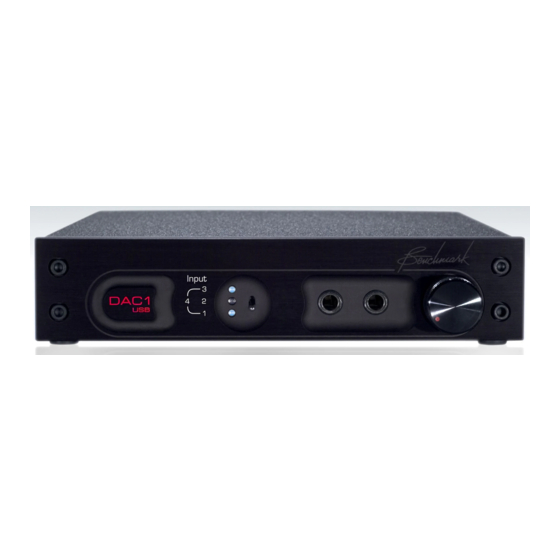
Page 6: Front Panel
The width of the DAC1 panel is exactly ½ that of a standard 19” panel. The DAC1 is one rack unit high. Either ear of the DAC1 can be mounted directly to a standard 19” rack. A machined junction block connects the other ear to a ½... -
Page 7: Rear Panel
Most professional equipment will work well at these levels. Note: The DAC1 is shipped with the Output Level switch set to Variable. The Calibration Potentiometers have no effect on the output levels when this switch is set to Variable. -
Page 8: Analog Outputs
RCA jacks is 2.5 kΩ and is high enough to allow mono summing with a “Y” cable and high enough to protect the DAC1 from wiring errors (wiring errors on the RCA outputs will not cause distortion on the XLR outputs). -
Page 9: Digital Inputs
DIGITAL INPUTS: There are three digital inputs on the DAC1. These inputs are selected from a front panel toggle switch. All of the inputs can decode AES/EBU and S/PDIF input signals in either professional or consumer formats. The DAC1 will not decode AC3 signals. -
Page 10: Specifications
Benchmark Media Systems, Inc. SPECIFICATIONS: DIGITAL INPUTS: Number of Digital Inputs (switch selected): 3, (XLR, Coaxial, Toslink) Number of Audio Channels: Input Sample Frequency Range: 28 to 195 kHz Maximum Input Word Length 24-bits Digital Input Impedance on XLR input: 110 Ω... -
Page 11: Audio Performance
Maximum Amplitude of AC line related Hum & Noise: < -126 dB Interchannel Differential Phase (Stereo Pair): +/- 0.5 degrees at 20 kHz Interchannel Differential Phase (Between DAC1 Units): +/- 0.5 degrees at 20 kHz Delay (Digital Input to Analog Output): 1.01 mS + (48/Fs) 2.10 ms at 44.1 kHz... -
Page 12: Led Status Indicators
9.33” (237 mm) Overall depth including connectors but without power cord or BNC-to-RCA adapter. 9.5” (249 mm) Wide 1.725” (44.5 mm) High WEIGHT: DAC1 only: 3.5 lb. DAC1 with power cord, BNC-to-RCA adapter, and manual: 4.5 lb. Rack mount kit (blank panel, junction block, and rack-mount screws): 0.32 lb. Shipping weight: 7 lb. -
Page 13: Removing Top Cover
Benchmark Media Systems, Inc. REMOVING TOP COVER: The DAC1 has a removable cover. This cover provides access to the jumper settings on the PCB. The DAC1 contains static sensitive components and should only be opened by qualified technicians. Static discharge may cause component failures, may affect the long-term reliability, or may degrade the audio performance. -
Page 14: Jumper Locations
Benchmark Media Systems, Inc. JUMPER LOCATIONS: Figure 1. – DAC1 Jumper Locations DAC 1 - Manual - Rev B.doc Page 14 of 37 1/2/2003... -
Page 15: Jumper Settings
A 2-pin jumper on header P2 (see Photo 1) can be used to disable the front-panel source-selection switch. This feature is useful when the DAC1 is in a critical audio path, and only one of the three digital inputs will be used. In such an application, the digital source selection can be made using the jumper on header P2. - Page 16 (see Photo 2). This termination is required for normal operation, but may be removed if the user wishes to loop a single coaxial feed through several other pieces of equipment (using a BNC “T” adapter on the DAC1). A 75 Ω...
- Page 17 Benchmark Media Systems, Inc. XLR Output Attenuation Jumpers (P5, P6, P7, and P8): One pair of 8-pin headers controls the output level at each XLR jack as follows: • 0 dB ***(Attenuator disabled) – (Jumper plug between pins 1 and 2 of each header) •...
-
Page 18: Compliance And Safety Information
For continued fire hazard protection, fuses should be replaced ONLY with the exact value and type as indicated on the rear panel. Do NOT substitute parts or make any modifications without the written approval of Benchmark Media Systems, Inc. Doing so may create safety hazards and void the warranty. -
Page 19: Warranty
In the event of failure of a product under this warranty, Benchmark Media Systems, Inc. will repair, at no charge, the product returned to its factory. Benchmark Media Systems, Inc. may, at its option, replace the product in lieu of repair. If the failure has been caused by misuse, neglect, accident or abnormal operating conditions, repairs will be billed at the normal shop rate. -
Page 20: Ultralock
AES/EBU signal that can be decoded by the AES/EBU receiver will be reproduced without the addition of any measurable jitter artifacts. The DAC1, DAC-104 and the ADC-104 employ Benchmark’s new UltraLock™ technology to eliminate all jitter- induced performance problems. UltraLock™ technology isolates the conversion clock from the digital audio interface clock. - Page 21 Benchmark Media Systems, Inc. Jitter creates “new audio” that is not harmonically related to the original audio signal. This “new audio” is unexpected and unwanted. It can cause a loss of imaging, and can add a low and mid frequency “muddiness” that was not in the original audio.
- Page 22 It is therefor important to attack jitter at both ends of the audio chain. The DAC1 is a great start, as it will allow accurate assessment of various A/D converters.
-
Page 23: Dac1 Performance Curves
Frequency Response at Fs = 48 kHz The above graphs show the frequency response of the DAC1 when it is operating at a 48 kHz sample rate. The top graph shows that the differential phase is better than ± 0.5º at 20 kHz. The bottom graph shows the amplitude response on a highly expanded 0.05 dB/division scale. - Page 24 Frequency Response at Fs = 96 kHz The above graphs show the frequency response of the DAC1 when it is operating at a 96 kHz sample rate. The top graph shows that the differential phase is better than ± 0.5º at 20 kHz and better than ± 1º at 43 kHz. The bottom graph shows the amplitude response on a highly expanded 0.05 dB/division scale.
- Page 25 Analysis of Idle Channel Noise The above graph demonstrates that the DAC1 is free from idle tones and clock crosstalk. The highest spurious tone measures –128 dBFS and is AC line related hum. The highest non-line related tone measures –138 dBFS.
- Page 26 Multiple DAC1 converters may be used to create a multi-channel playback system that maintains phase accuracy across all channels. The above graph shows the differential phase between 10 audio channels using 5 DAC1 converters. The DAC1 converts were chosen at random from stock and measurements were made using a random combination of Coaxial, XLR, and Optical inputs.
- Page 27 20 Hz to 20 kHz is very slight). Note that at worst case, the distortion is 110 dB less than the – 3 dBFS test tone (and 114 dB less than the full scale output of the DAC1). This implies that the distortion created by the DAC1 should be below the threshold of hearing unless playback levels exceed 114 dB peak SPL.
- Page 28 Benchmark Media Systems, Inc. THD+N vs. Level at 1 kHz – Balanced Outputs Below –4 dBFS, distortion is lower than the noise floor of the converter. Above –3 dBFS, distortion reaches a maximum value of only –107 dBFS. DAC 1 - Manual - Rev B.doc...
- Page 29 This graph shows the output of the HPA2™ headphone amp driving a 60-Ohm load at a very high level (+14 dBu). Even under these conditions, the HPA2™ delivers the full rated performance of the DAC1. Compare this to the performance of the balanced outputs (see previous graph).
- Page 30 Benchmark Media Systems, Inc. THD+N vs. Level at 1 kHz - Unbalanced Outputs This graph demonstrates the performance of the unbalanced outputs. Note that the performance is nearly identical to that of the balanced outputs. DAC 1 - Manual - Rev B.doc...
- Page 31 Benchmark Media Systems, Inc. THD+N vs. Sample Frequency The above graph shows that the DAC1 provides consistent performance at all sample rates. Distortion is not a function of sample rate. The minor variations in the above plots are due to measurement limitations.
- Page 32 The graph above shows the results of a standard AES jitter tolerance test. The top (red) curve shows the amplitude of the jitter applied to the inputs of the DAC1. The scale for the top curve is on the right hand side of the graph and is calibrated in UI of jitter.
- Page 33 We set the interface jitter amplitude to its maximum value of 12.75 UI (2075 ns) of jitter. We then swept the jitter frequency from 2 Hz to 9 kHz and plotted the THD+N from the DAC1. Absolutely no change in THD+N was observed at any test frequency, and the DAC1 performance did not change when the jitter was turned off.
- Page 34 Benchmark Media Systems, Inc. DAC1 Cable Jitter Immunity The above FFT plots demonstrate that the performance of the DAC1 is not degraded in any way when long cables are used to transmit digital audio to the DAC1. DAC 1 - Manual - Rev B.doc...
- Page 35 XLR Digital Input Sensitivity The above graph shows that the performance of the DAC1 is not a function of the signal level at the XLR digital input. When the signal is too low to decode (< 160 mVpp), the converter mutes gracefully.
- Page 36 Coaxial Digital Input Sensitivity The above graph shows that the performance of the DAC1 is not a function of the signal level at the coaxial digital input. When the signal is too low to decode (< 120 mVpp), the converter mutes gracefully.
- Page 37 AES. Also, the above plots show that the AES minimum eye pattern specifications are barely met at the end of 1000 feet of Category 5 twisted pair cable. The high sensitivity of the DAC1 receivers allows reliable operation at the end of a 1000 foot cable.
Need help?
Do you have a question about the DAC1 and is the answer not in the manual?
Questions and answers