
Related Manuals for Benchmark DAC1 USB


Summary of Contents for Benchmark DAC1 USB
- Page 1 DAC1 USB Benchmark Instruction Manual 2-Channel 24-bit 192-kHz Audio Digital-to-Analog Converter...
-
Page 2: Safety Information
OR MAKE ANY MODIFICATIONS TWO SETTINGS: ‘110’ AND ‘220’. CHECK WITHOUT THE WRITTEN APPROVAL OF TO SEE THAT IT IS PROPERLY BENCHMARK MEDIA SYSTEMS, INC. CONFIGURED FOR YOUR LOCATION MODIFICATION MAY CREATE SAFETY BEFORE CONNECTING AC POWER. HAZARDS AND VOID THE WARRANTY. -
Page 3: Faceplate Options
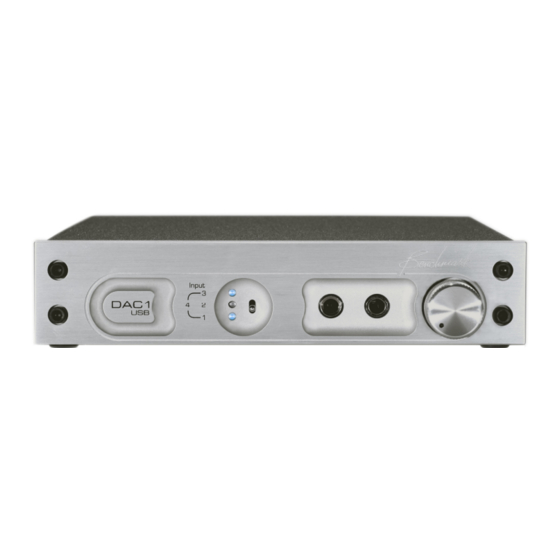
Faceplate Options The DAC1 USB is available with 3 different faceplates. The internal electronics are identical in all versions. Black Silver Black Rack-Mount DAC1 USB Instruction Manual Revision D Page 3... -
Page 4: Table Of Contents
RoHS Compliant Information Volume Control CE Certificate of Compliance Rear Panel Warranty Information Input 1 - SPDIF/AES BNC Benchmark 1 Year Warranty Input 2 – AES/EBU XLR Benchmark Extended Warranty Input 3 – Optical Internal Settings Input 4 – USB... -
Page 5: Features
RCA outputs are preset to +2 Vrms (8.2 dBu) at 0 dBFS in Calibrated mode Headphone jack 1 mutes XLR and RCA outputs (feature may be disabled) Benchmark’s phase-accurate UltraLock™ technology for total jitter immunity Status LED’s - display input selection and error conditions Automatic Standby Mode –... -
Page 6: Overview
The rugged and compact rack-mount option DAC1 Heritage makes the DAC1 USB an excellent choice for location recording, broadcast facilities, and The pristine audio path of the award-winning mobile trucks. DAC1 has made it the Benchmark of stand- alone D/A converters. -
Page 7: Jitter-Immune Ultralock
XLR and RCA analog outputs when a headphone plug is inserted. The DAC1 USB is designed to avoid all This mute feature can be disabled with unnecessary mute scenarios. Muting is only internal jumpers. -
Page 8: Error Display
This flashing will stop when the Phase-Accurate Multi-Track and error is corrected. If the error persists for more than 15 seconds, the DAC1 USB will enter Standby Mode. The DAC1 is phase-accurate between channels at all sample rates, and is phase... -
Page 9: Front Panel
• Data transmission errors - 16 flashes – audio muted If the DAC1 USB is in Standby Mode it will resume normal operation when the Input • Non-PCM – 16 flashes – audio muted Selector Switch is toggled. -
Page 10: Standby Mode
Instructions for setting the XLR pads are the level at both jacks. detailed in the ‘Internal Settings’ section of this manual. The DAC1 USB is shipped with Because of the variations in headphone the XLR attenuation set to -20 dB. -
Page 11: Rear Panel
0.5 Vpp consumer-format digital audio signals (commonly known as S/PDIF). The coaxial The Benchmark UltraLock™ system removes input on the DAC1 USB is designed to accept interface jitter from all inputs. The result is either type of signal. that all digital inputs have identical jitter performance. -
Page 12: Input 2 - Aes/Ebu Xlr
1.1 or USB 2.0 connector. An ‘A-B type’ USB user wishes to loop a single coaxial feed cable is provided with the DAC1 USB. The through several other pieces of USB cable connects the DAC1 USB directly to equipment. -
Page 13: Output Level Switch
Volume Control). TIP: If the DAC1 USB is being used in a The DAC1 USB has two unbalanced RCA critical signal chain (such as a broadcast outputs and two balanced XLR outputs. -
Page 14: Unbalanced Rca Analog Outputs
DAC1 USB. The consumption, and may cause distortion. DAC1 USB ships with the 20 dB pads enabled. Unbalanced RCA Analog TIP: When directly driving power amplifiers and powered speakers, use Outputs ‘Variable’... -
Page 15: Calibration Trimmers
USB will operate normally over a range of 90 on most power amplifiers. Most professional to 140 VAC. At 220, the DAC1 USB will equipment will work well at these levels. operate normally over a range of 175 to 285 Note: The Calibration Trimmers have no VAC. -
Page 16: Rack Mounting
Rack Mounting Rack Mount Coupler (DAC1 USB Black RM only) The rack-mount version of the DAC1 USB is part of Benchmark’s ½-wide System1™ product family. Each is one rack unit high and is exactly ½ the width of a standard 19”... -
Page 17: Benchmark Technologies
HPA2™ Headphone Amplifier Ohm headphone loads are virtually identical. The HPA2™ will substantially improve the The DAC1 USB headphone output is driven sound of 30 and 60-Ohm headphones. It will by Benchmark’s signature HPA2™ headphone make very noticeable improvements with amplifier. -
Page 18: Ultralock™ Clock System
Fortunately, interface jitter has absolutely no measurable jitter artifacts. effect on the audio unless it influences the The DAC1 USB, DAC1, DAC-104, ADC1 and conversion clock in an analog-to-digital the ADC-104 employ Benchmark’s converter (A/D) or in a digital-to-analog UltraLock™... - Page 19 Again, these are only partial solutions function is the removal of high-frequency because jitter even accumulates in these signals that originate inside the converter clock distribution systems. Furthermore, a box, or even originate inside the converter IC. DAC1 USB Instruction Manual Revision D Page 19...
- Page 20 A/D performance without a good D/A. The consistent performance delivered by the What UltraLock™ converters DAC1 USB eliminates one major variable: cannot do: jitter. UltraLock™ converters cannot undo damage that has already been done. If an A/D with a...
-
Page 21: Advanced Usb Audio Technology
96 kHz, 24- (memory and CPU) than native solutions. bit, the Benchmark USB solution is a dream- come-true for lovers of high quality audio It is also interesting that many of the ASIO playback. - Page 22 This up- instantaneously recognize the presence of the sampling is so well designed that it should not Benchmark USB device. Any audio played be capable of generating audible artifacts. from the computer will then be routed to the Nevertheless, if true bit-transparent operation Benchmark USB device immediately.
- Page 23 16-bit word-length reduction. to match the audio, and the system volume control is set to 100%. Benchmark’s Advanced USB Audio technology breaks the 16-bit barrier and delivers pristine digital audio to the D/A Advantages of 24-bit Playback of converter.
-
Page 24: Performance Graphs
Performance Graphs The following graphs apply to both DAC1 and DAC1 USB converters: Frequency Response Tests Frequency Response at Fs = 48 kHz The above graphs show the frequency response of the DAC1 when it is operating at a 48-kHz sample rate. - Page 25 0.05 dB/division scale. The amplitude response is down by only 0.22 dB at 20 kHz and only –1 dB at 43 kHz. The bass response extends well below the 10-Hz limitation of the measurement equipment. DAC1 USB Instruction Manual Revision D...
-
Page 26: Fft Analysis Of Idle Channel Noise
The above graph demonstrates that the DAC1 is free from idle tones and clock crosstalk. The highest spurious tone measures –128 dBFS and is AC line related hum. The highest non-line related tone measures –138 dBFS. DAC1 USB Instruction Manual Revision D... -
Page 27: Multi-Unit Phase Response
Multi-Unit Phase Response Any combination of DAC1 and DAC1 USB converters may be used to create a multi-channel playback system that maintains phase accuracy across all channels at sample rates up to 110 kHz. The above graph shows the differential phase between 10 audio channels using 5 DAC1 converters operating at 96 kHz. -
Page 28: Thd+N Tests
DAC1). This implies that the distortion created by the DAC1 should be below the threshold of hearing unless playback levels exceed 112 dB peak SPL. Distortion should still be well masked at higher playback levels. DAC1 USB Instruction Manual Revision D... - Page 29 THD+N vs. Level at 1 kHz – Balanced Outputs Below –4 dBFS, distortion is lower than the noise floor of the converter. Above –3 dBFS, distortion reaches a maximum value of only –107 dBFS. DAC1 USB Instruction Manual Revision D...
- Page 30 This graph shows the output of the HPA2™ headphone amp driving a 60-Ohm load at a very high level (+14 dBu). Even under these conditions, the HPA2™ delivers the full rated performance of the DAC1. Compare this to the performance of the balanced outputs (see previous graph). DAC1 USB Instruction Manual Revision D...
- Page 31 THD+N vs. Level at 1 kHz - Unbalanced Outputs This graph demonstrates the performance of the unbalanced outputs. Note that the performance is nearly identical to that of the balanced outputs. DAC1 USB Instruction Manual Revision D Page 31...
- Page 32 The above graph shows that the DAC1 provides consistent performance at all sample rates. Distortion is not a function of sample rate. The minor variations in the above plots are due to measurement limitations. DAC1 USB Instruction Manual Revision D...
-
Page 33: Jitter Tests
In fact, the DAC1 can tolerate much higher levels of jitter without any measurable change in performance (see the next graph). DAC1 USB Instruction Manual Revision D Page 33... - Page 34 DAC1 performance did not change when the jitter was turned off. The same test was conducted using FFT analysis to look for jitter-induced artifacts. No change was observed on a FFT analysis (see the next graph). DAC1 USB Instruction Manual Revision D...
- Page 35 Immunity to Cable-Induced Jitter The above FFT plots demonstrate that the performance of the DAC1 is not degraded in any way when long cables are used to transmit digital audio to the DAC1. DAC1 USB Instruction Manual Revision D Page 35...
-
Page 36: Input Sensitivity Tests
The above graph shows that the performance of the DAC1 is not a function of the signal level at the XLR digital input. When the signal is too low to decode (< 160 mVpp), the converter mutes gracefully. DAC1 USB Instruction Manual Revision D... - Page 37 The above graph shows that the performance of the DAC1 is not a function of the signal level at the coaxial digital input. When the signal is too low to decode (< 120 mVpp), the converter mutes gracefully. DAC1 USB Instruction Manual Revision D...
- Page 38 1000 feet of Category 5 UTP cable, the DAC1 receivers have enough sensitivity to allow reliable operation. The jitter produced by this connection is removed entirely by the Benchmark UltraLock™ clock circuits and the DAC1 operates at full-specified performance.
-
Page 39: Volume Control Curve
Volume Control Curve Volume Control 10.0 -10.0 -20.0 -30.0 -40.0 -50.0 -60.0 -70.0 -80.0 Rotation (Steps) Volume Control - Step Size Rotation (Steps) DAC1 USB Instruction Manual Revision D Page 39... -
Page 40: Specifications
Maximum Amplitude of Spurious Tones with 0 dBFS test < -126 dB signal Maximum Amplitude of Idle Tones < -128 dB Maximum Amplitude of AC line related Hum & Noise < -126 dB DAC1 USB Instruction Manual Revision D Page 40... -
Page 41: Group Delay (Latency)
Inter-channel Differential Phase (Stereo Pair – any +/- 0.5 degrees at 20 kHz sample rate) Inter-channel Differential Phase (Between DAC1 USB +/- 0.5 degrees at 20 kHz Units Fs<110 kHz) Inter-channel Differential Phase (Between DAC1 USB +/- 4.1 degrees at 20 kHz Units Fs>110 kHz) -
Page 42: Digital Audio Inputs
>1.2 UI sine at 40 kHz >0.4 UI sine at 80 kHz >0.29 UI sine at 90 kHz >0.25 UI sine above 160 kHz Jitter Attenuation Method Benchmark UltraLock™ - all inputs DAC1 USB Instruction Manual Revision D Page 42... -
Page 43: Balanced Analog Outputs
Output Level Range (at 0 dBFS) In ‘Variable’ Mode Off to +11 dBu Calibration Adjustability 2 dB / turn Output Level Variation with Sample Rate (44.1 kHz vs. < +/- 0.006 dB 96 kHz) Factory Preset 2vRMS (8.2 dBu) DAC1 USB Instruction Manual Revision D Page 43... -
Page 44: Hpa2 Tm Headphone Outputs
220 V setting: 175 V min, 285 V max Frequency 50-60 Hz Power 8 Watts Idle 8 Watts Typical Program 16 Watts Maximum Fuses 5 x 20 mm (2 required) ® 0.5 A 250 V Slo-Blo Type DAC1 USB Instruction Manual Revision D Page 44... -
Page 45: Dimensions
9.5” (249 mm) Height 1.725” (44.5 mm) Weight DAC1 USB only 3.5 lb. DAC1 USB with power cord, 3 BNC-to-RCA adapters, 4.5 lb. extra fuses, and manual Rack mount kit (blank panel, junction block, and rack- 0.32 lb. mount screws) Shipping weight 7 lb. -
Page 46: Regulatory Compliance
(European Union) directive 2002/95/EC, or, RoHS (Restrictions of Hazardous Substances). As of July 01, 2006, All Benchmark Media Systems, Inc. products placed on the European Union market are compliant (containing quantity limit weight less than or equal to 0.1% (1000 ppm) of any homogeneous Lead (Pb), Mercury (Hg), Hexavalent Chromium (Cr VI), and flame retardant Polybrominated Biphenyls (PBB) or Polybrominated Diphenyl Ethers (PBDE)). -
Page 47: Ce Certificate Of Compliance
CE Certificate of Conformity DAC1 USB Instruction Manual Revision D Page 47... -
Page 48: Warranty Information
In the event of failure of a product under this warranty, Benchmark Media Systems, Inc. will repair, at no charge, the product returned to its factory. Benchmark Media Systems, Inc. may, at its option, replace the product in lieu of repair. -
Page 49: Benchmark Extended Warranty
Benchmark Extended Warranty The Benchmark Extended 5* Year Warranty Benchmark Media Systems, Inc. optionally extends the standard one (1) year warranty to a period of five (5)* years from the date of delivery. *For the extended warranty to become effective, the original purchaser must register the product at the time of purchase either by way of the prepaid registration card or through the product registration section of the Benchmark Media Systems, Inc. -
Page 50: Internal Settings
Internal Settings XLR jacks. CAUTION: Do not remove jumpers at JP3, Removing Top Cover JP4, JP5, and JP6. The DAC1 USB will not function without these jumpers. The DAC1 USB cover must be removed to Jumpers should never be installed on gain access to the jumpers. - Page 51 (using a BNC ‘T’ adapter on the DAC1 USB). A 75- Ohm termination must be applied at the last device on the loop, and there should be a...
- Page 52 JP8 and JP9 are factory installed to reduce the headphone output by 10 dB. This setting is best for most applications. Remove the jumpers if you need more gain. Copyright © 2007 Benchmark Media Systems, Inc. All rights reserved. Photo 4 – Headphone Gain Reduction Benchmark Media Systems, Inc.
Need help?
Do you have a question about the DAC1 USB and is the answer not in the manual?
Questions and answers