Table of Contents
Advertisement
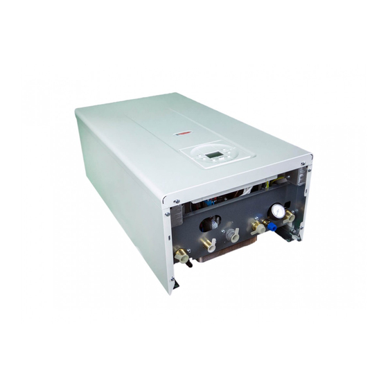
Wall mounted instantaneous combi boiler
CE
0694
RKR 24_28_34 - RAD - ING - MAN.INST - 1104A - DIGITECH 2 - REGNO UNITO - EXTRAHEAT
Technical specification RADIANT BRUCIATORI S.p.A. Montelabbate (PU) ITALY
Instruction Manual
Installation, operating, commissioning and maintenance instructions
premix condensing boiler
for model
RKR 24
RKR 28
RKR 34
- CBD
ENGLISH
Advertisement
Table of Contents


Need help?
Do you have a question about the RKR 24 and is the answer not in the manual?
Questions and answers