
Subscribe to Our Youtube Channel
Related Manuals for Sensaphone SENSAPHONE 400


Summary of Contents for Sensaphone SENSAPHONE 400
- Page 1 SENSAPHONE ® REMOTE MONITORING SOLUTIONS SENSAPHONE ® User’s Manual Stay informed and in control of vital environmental conditions and processes with the fully-programmable Sensaphone 400. ® LIT-0129...
- Page 3 SENSAPHONE ® Model 400 User’s Manual Version 1.5.1...
- Page 4 Every effort has been made to ensure that the information in this docu- ment is complete, accurate and up-to-date. PHONETICS, Inc. assumes no responsibility for the results of errors beyond its control. PHONETICS, Inc. also cannot guarantee that changes in equipment made by other manufac- turers, and referred to in this manual, will not affect the applicability of the information in this manual.
-
Page 5: Important Safety Instructions
IMPORTANT SAFETY INSTRUCTIONS Your Model 400 has been carefully designed to give you years of safe, reli- able performance. As with all electrical equipment, however, there are a few basic precautions you should take to avoid hurting yourself or damaging the unit: •... -
Page 6: Fcc Requirements
SENSAPHONE 400 User’s Manual • Avoid using a telephone (other than a cordless type) during an electrical storm. There may be a remote risk of electric shock from lightning. • Do not use the telephone to report a gas leak in the vicinity of the leak. - Page 7 If you experience trouble with this equipment, or you need information on obtaining service or repairs, please contact: PHONETICS, INC. 901 Tryens Road, Aston, PA 19014 877-373-2700 Fax: 610-558-0222 The telephone company may ask that you disconnect this equipment from the network until the problem has been corrected or until you are sure that the equipment is not malfunctioning.
- Page 8 SENSAPHONE 400 User’s Manual Canadian Department of Communications Statement Notice: The Canadian Department of Communications label identi- fies certified equipment. This certification means that the equip- ment meets certain telecommunications network protective opera- tional and safety requirements. The Department does not guarantee the equipment will operate to the user’s satisfaction.
-
Page 9: Year Limited Warranty
1 YEAR LIMITED WARRANTY PLEASE READ THIS WARRANTY CAREFULLY BEFORE USING THE PRODUCT. THIS LIMITED WARRANTY CONTAINS SENSAPHONE’S STANDARD TERMS AND CONDITIONS. WHERE PERMITTED BY THE APPLICABLE LAW, BY KEEPING YOUR SENSAPHONE PRODUCT BEYOND THIRTY (30) DAYS AFTER THE DATE OF DELIVERY, YOU FULLY ACCEPT THE TERMS AND CONDITIONS SET FORTH IN THIS LIMITED WARRANTY. - Page 10 SENSAPHONE 400 User’s Manual RESPONSIBLE FOR PAYMENT OF ANY INCIDENTAL, CONSEQUENTIAL, SPECIAL AND/OR PUNITIVE DAMAGES OF ANY KIND, INCLUDING BUT NOT LIMITED TO ANY LABOR COSTS, PRODUCT COSTS, LOST REVENUE, BUSINESS INTERRUPTION LOSSES, LOST PROFITS, LOSS OF BUSINESS, LOSS OF DATA OR INFORMATION, OR FINANCIAL LOSS, FOR CLAIMS OF...
- Page 11 OR COSTS, INCLUDING BUT NOT LIMITED TO DAMAGES THAT ARE DIRECT OR INDIRECT, INCIDENTAL, SPECIAL OR CONSEQUENTIAL, AND INCLUDING ATTORNEYS FEES AND LEGAL COSTS, THAT MAY RESULT FROM THE INSTALLATION, OPERATION, USE OF, OR INABILITY TO USE WARRANTORS’ PRODUCTS AND SERVICES, OR FROM THE FAILURE OF THE WARRANTORS’...
- Page 12 SENSAPHONE 400 User’s Manual herein may give you specific legal rights that will depend upon the applicable law. You may also have other legal rights depending upon the law in your juris- diction. 6. CHOICE OF FORUM AND CHOICE OF LAW: In the event that a dispute...
-
Page 13: Table Of Contents
table of Contents Chapter 1: IntroduCtIon . . . . . . . . . .17 Feature Summary . . . . . . . . . . . . . . . . . . . . . . . . . . . . . 18 about thIS manual . - Page 14 SENSAPHONE 400 User’s Manual 4 .3 dIal-out telephone numberS . . . . . . . . . . . . . . . . 43 4.3.1 Programming Dial-out Telephone Numbers .
- Page 15 4 .15 the CloCk . . . . . . . . . . . . . . . . . . . . . . . . . . . . . . . 63 4.15.1 Setting the Clock .
- Page 16 SENSAPHONE 400 User’s Manual Chapter 6: aCknowledgment, StatuS report & remote aCCeSS . . . . . . . . . . .85 6 .1 alarm aCknowledgment . . . . . . . . . . . . . . . . . . .85 6.1.1 Local Acknowledgment .
- Page 17 appendIx C: 400 QuICk reFerenCe . . .119 appendIx d: aCCeSSorIeS . . . . . . . . . .123 appendIx e: SpeCIFICatIonS . . . . . . . .125 Alert Zones .
- Page 18 SENSAPHONE 400 User’s Manual...
-
Page 19: Chapter 1: Introduction
Chapter 1: Introduction Chapter 1: IntroduCtIon The Sensaphone® Model 400 is a fully-programmable, environmental moni- toring system that offers extensive on-site and remote monitoring capabili- ty to small businesses, private homes, farms, greenhouses, computer rooms, and remote facilities. Designed for desktop or wall mounting, the Model 400 is simple to install, program and operate;... -
Page 20: Feature Summary
SENSAPHONE 400 User’s Manual Feature Summary The Sensaphone 400 includes the following features: • Four zones configurable as temperature or dry contact • Each zone can be individually enabled or disabled • Fully automatic input configuration • Temperature sensor included on zone #1 •... -
Page 21: Layout
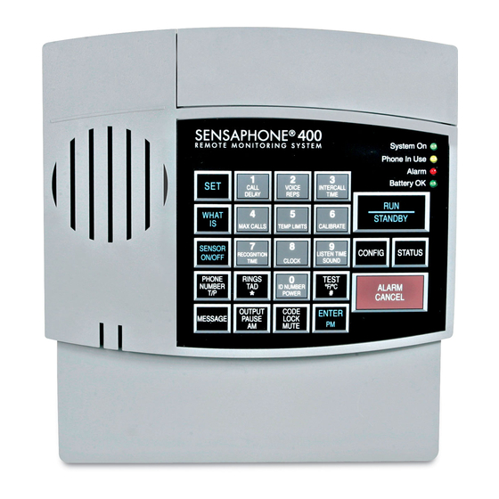
Chapter 1: Introduction layout 1. Programming Keypad 2. Power Jack 3. Phone Extension Jack 4. Phone Line Jack 5. Speaker 6. Built in Microphone 7. System on LED 8. Phone-in-use LED 9. Alarm LED 10. Battery OK LED 11. Battery Compartment 12. -
Page 22: Technical Support
SENSAPHONE 400 User’s Manual Battery OK LED On: Battery condition good LED Blinking: Battery condition low LED Off: No battery/critically low battery condition teChnICal Support If any questions arise upon installation or operation of the Model 400, please contact the Sensaphone Technical Service Department at the num- ber shown below, and have the following information: •... -
Page 23: Chapter 2: Installation
Chapter 2: Installation Chapter 2: InstallatIon Correctly installing the Model 400 will ensure proper functioning of the unit. Please read the entire chapter before starting the installation process. Within the packaging will be a Warranty Registration Card. Please take the time to fill this out and mail. -
Page 24: Power Supply And Battery Backup
When the DC power transformer is first plugged into the electrical outlet, the Model 400 automatically starts in RUN mode. The System On light will begin to glow. The unit will respond with,“Hello, this is Sensaphone 400. ” 2 .6 run mode and Standby mode Pressing the RUN/STANDBY key on the Model 400 keypad will alternately activate or deactivate the unit. -
Page 25: Telephone Line
Chapter 2: Installation In RUN mode, the Model 400 is able to receive incoming calls and to dial out automatically in the event of an alarm on one of the monitored condi- tions. To enter STANDBY mode, press RUN/STANDBY. As soon as the Model 400 enters STANDBY mode, it responds with “Goodbye. - Page 26 SENSAPHONE 400 User’s Manual To install the telephone line, plug one end of the modular cord into the “line” jack on the back of the model 400 (as shown) and plug the other end into any standard RJ11 phone outlet.
-
Page 27: The Microphone
Chapter 2: Installation 2 .8 the mICrophone The Model 400 is provided with a built-in microphone which is used to monitor high sound levels produced near the installation site. The sensitiv- ity of the microphone is configurable and will detect a continuous as well as a pulsating alarm. -
Page 28: Installing The Sensor
SENSAPHONE 400 User’s Manual tion and compare that value to programmed high and low temperature limits. Temperature zones must be used with Sensaphone’s 2.8K Remote Temperature Sensor or weatherproof sensor. NOTE: Before wiring, it is advisable to disable the zones to prevent accidentally tripping an alarm. -
Page 29: Multiple Sensors
Chapter 2: Installation ZONES Sensor wired to Sensor wired to Alert Input 2 Alert Input 3 Figure 2-7 Two Sensors Wired to Adjacent Zones NOTE: Do not use sensors, switches, or relays that supply any voltage or current to the Model 400. Be aware of proximity to other electrical wires or components when placing wires that lead from the sensors to the unit. - Page 30 SENSAPHONE 400 User’s Manual ZONES Multiple normally-closed sensors wired in series (example using Input 2) Alert condition occurs when a switch is opened Figure 2-8. Multiple Normally Closed Sensors To wire several normally open sensors to one alert zone, connect them in parallel.
-
Page 31: Outdoor Wiring
Chapter 2: Installation 2 .12 outdoor wIrIng When wiring sensors outdoors, DO NOT allow exposed wires to run freely in open air; under such conditions, the Model 400 is susceptible to serious damage during a lightning storm. Depending upon the distance outdoor wiring must travel, consideration should be given to the use of shielded wire inside a metal conduit. - Page 32 SENSAPHONE 400 User’s Manual...
-
Page 33: Chapter 3: Quick Start
PAUSE LOCK MUTE Figure 3-1. The Model 400 Keypad 3 .2 preparatIon For programmIng Sensaphone 400 Keypad Part # KEY - 0017 Read complete instructions in Chapter 2: Installation, and make sure to fol- Rev C 5/23/2006 low these three steps first:... -
Page 34: Quick-Start Programming Steps
SENSAPHONE 400 User’s Manual 3 .3 QuICk-Start programmIng StepS STEP 1: SET CONfIgUrATION Of ZONES The Model 400 will scan the 4 external zones and determine if they are N.O. (normally open), N.C. (normally closed), or Temperature. If external sensors are added, make sure they are in their normal positions before proceeding—refer to Chapter 5, Section 5.1. - Page 35 Chapter 3: Quick Start 3. Using the number keys, enter the digits (up to 16 are permitted) for the ID number. The Model 400 will recite the digits as they are pressed. CALL VOICE INTERCALL REPS TIME DELAY MAX CALLS TEMP LIMITS CALIBRATE LISTEN TIME...
- Page 36 SENSAPHONE 400 User’s Manual 4. Enter the complete telephone number using the number keys. The Model 400 will recite the digits as they are pressed. CALL VOICE INTERCALL REPS TIME DELAY MAX CALLS TEMP LIMITS CALIBRATE LISTEN TIME RECOGNITION CLOCK...
- Page 37 Chapter 3: Quick Start The Model 400 responds: “Enter low temperature limit. ” 4. Using the number keys, enter a value for low temperature limit. The Model 400 will recite the digits as they are pressed. If a negative number is required, first press *, then enter the number.
-
Page 38: Summary Of The Alarm Dial-Out Process
SENSAPHONE 400 User’s Manual To gain a basic understanding of how the alarm dial-out feature works, refer to this chapter, Section 3-4. For extended information regarding dial-out and related programmable parameters, refer to Chapter 7: Operation. 3 .4 Summary oF the alarm dIal-out proCeSS Action—Response... - Page 39 Chapter 3: Quick Start 4. THE ALARM IS • Max Calls ACKNOWLEDGED This is the total number of telephone When the alarm is calls that will be dialed in response acknowledged, the dial-out to any valid alarm. Telephone process is cancelled and the numbers are dialed sequentially, and audible, on-site alarm message continue to cycle until the maximum...
- Page 40 SENSAPHONE 400 User’s Manual...
-
Page 41: Chapter 4: Communications
Chapter 4: Communications Programming Chapter 4: CommunICatIons programmIng This chapter explains the keypad commands for communications program- ming of the Model 400, including interrogation and resetting of the follow- ing: • Voice Messages • The Unit ID Number • Dial-out Telephone Numbers •... - Page 42 SENSAPHONE 400 User’s Manual To program the ID Message: 1. Press the SET key. 2. Press the MESSAGE key. The 400 will say “Enter Message Number. ” MESSAGE 3. Press the ID key (number 0 key). ID NUMBER POWER 4. When the unit beeps, begin speaking your message into the microphone.
- Page 43 Chapter 4: Communications Programming 2. Press the MESSAGE key. The 400 will say, “Enter Message Number. ” MESSAGE 3. Press the number key for the corresponding Zone. VOICE INTERCALL CALL DELAY REPS TIME MAX CALLS CALIBRATE TEMP LIMITS LISTEN TIME RECOGNITION CLOCK SOUND...
-
Page 44: The Unit Id Number
SENSAPHONE 400 User’s Manual To erase a Zone or ID message: 1. Press the SENSOR ON/OFF key. SENSOR ON/OFF 2. Press the MESSAGE key. MESSAGE The 400 will say “Enter message number. ” 3. Press the Zone Number or ID key. -
Page 45: Interrogating The Id Number
Chapter 4: Communications Programming 3. Using the number keys, enter up to 16 digits for the ID number. The Model 400 will recite the digits as they are pressed. CALL VOICE INTERCALL REPS TIME DELAY MAX CALLS TEMP LIMITS CALIBRATE LISTEN TIME RECOGNITION CLOCK... -
Page 46: Programming Dial-Out Telephone Numbers
SENSAPHONE 400 User’s Manual 4 .3 .1 programmIng dIal-out telephone numberS To program dial-out telephone numbers: 1. Press SET. 2. Press PHONE NUMBER. PHONE NUMBER 3. Select which telephone number to program. Press any unassigned num- ber key (from 1 to 4) to represent the new telephone number entry. The Model 400 will respond: “Enter number. -
Page 47: Erasing A Telephone Number
Chapter 4: Communications Programming 2. Press PHONE NUMBER. PHONE NUMBER 3. Press a number key (from 1 to 4). VOICE INTERCALL CALL REPS TIME DELAY MAX CALLS Model 400 will recite the corresponding telephone number. If there is no number programmed for a particular key, the unit will respond: “No num- ber. -
Page 48: Dial-Out Test Mode
SENSAPHONE 400 User’s Manual 4 .4 dIal-out teSt mode The 400 allows you to test your telephone programming by simulating an alarm dialout to any programmed telephone number. This can be a valu- able tool for insuring that your programming is correct and also for trou- bleshooting dialing problems. -
Page 49: Tone Or Pulse Dialing
Chapter 4: Communications Programming 3. Press 0 then ENTER to enter manual dialing mode. The 400 will go off-hook and you should hear a dial tone through the speaker. Press any number keys to dial a telephone number. ID NUMBER POWER 4. -
Page 50: Special Dialing Keys
SENSAPHONE 400 User’s Manual 4 .6 .1 SpeCIal dIalIng keyS The following designated keys represent special functions when used with PHONE NUMBER entries: 1. Pause OUTPUT PAUSE PAUSE represents a two-second pause in dialing. It can be used when an access number is required before dialing to an outside line. -
Page 51: Incorporating A Pause
Chapter 4: Communications Programming Code 2 Wait-for-Answer You can force your Sensaphone to Wait-For-Answer in the middle of dial- ing a telephone number. This is useful when calling a telephone extension that is initially answered by an auto-attendant. By inserting the wait-for- answer code you can instruct your Sensaphone to call the main number, then wait for an answer by the auto-attendant, then dial the extension. - Page 52 SENSAPHONE 400 User’s Manual 3. Press any unassigned number key (from 1 to 4) to represent the new tele- phone number entry. Model 400 will respond: “Enter number. ” CALL VOICE INTERCALL REPS TIME DELAY MAX CALLS 4. From the number keys, enter the access digit (i.e., 9). The Model 400 will recite the digit.
-
Page 53: Incorporating A Pound (#) Or Star (*)
Chapter 4: Communications Programming 4 .6 .3 InCorporatIng a pound (#) or Star (*) Incorporate a pound or star if it is normally included in tele- phone number: 1. Press SET. 2. Press PHONE NUMBER. PHONE NUMBER 3. Press any unassigned number key (from 1 to 4) to represent the new tele- phone number entry. -
Page 54: Special Dialing To A Beeper Or
SENSAPHONE 400 User’s Manual 4 .6 .4 SpeCIal dIalIng to a beeper or pager Your Sensaphone can be programmed to send an alarm message to a numeric beeper/pager. The message will include the Sensaphone’s tele- phone number (ID number) and the Zone numbers that are in alarm. For example, if zones 1 and 4 are in alarm, the message on your pager would be: 8882227777-1-4, where 8882227777 is the unit’s ID number. -
Page 55: Rings Until Answer
Chapter 4: Communications Programming 4 .7 rIngS untIl anSwer Rings Until Answer is the programmed number of times the telephone rings before the Model 400 will answer an incoming call. This can be set from 1 to 15 rings. The default value is 4. 4 .7 .1 programmIng rIngS untIl anSwer To program Rings Until Answer: 1. -
Page 56: Tad (Telephone Answering Device)
SENSAPHONE 400 User’s Manual 4 .8 tad (telephone anSwerIng devICe) The TAD feature is especially useful because it integrates the operation of the Model 400 with your telephone answering device (e.g. answering machine) in a way that retains the full flexibility of each system. This allows... -
Page 57: No Tad In Use
Chapter 4: Communications Programming 1. Dial the telephone number of the Model 400. 2. Let the telephone ring once and then hang up. 3. Wait approximately ten seconds 4. Call the Model 400 back. It will answer the telephone on the first ring. Explanation: The pattern of one ring, followed by a second call (within 30 seconds), signals the Model 400 to answer your incoming call, bypassing the telephone answering device. -
Page 58: Interrogating The Listen-In Time
SENSAPHONE 400 User’s Manual 2. Press LISTEN TIME. The Model 400 will respond: “Enter seconds. ” LISTEN TIME SOUND 3. Using the number keys, enter the seconds. The Model 400 will recite the digits as they are pressed. INTERCALL CALL... -
Page 59: Programming The Call Delay
Chapter 4: Communications Programming 4 .10 .1 programmIng the Call delay To program the Call Delay: 1. Press SET. 2. Press CALL DELAY. CALL DELAY The Model 400 will respond: “Enter minutes. ” 3. Using the number keys, enter the minutes. CALL VOICE INTERCALL... -
Page 60: Local Voice Mute
SENSAPHONE 400 User’s Manual 2. Press CALL DELAY. CALL DELAY The Model 400 will recite the programmed Call Delay. 4 .11 loCal voICe mute When the Model 400 dials out to report an alarm, it also audibly recites the alarm message through it’s speaker. The Local Voice Mute command allows you to turn off the speaker at the Model 400’s site during alarm dialouts... -
Page 61: Voice Repetitions
Chapter 4: Communications Programming 4 .12 voICe repetItIonS The Voice Repetitions feature allows programming of the number of times the alarm message is repeated per phone call during alarm dial-out. The maximum repetitions may be set to 10; the default is 3 repetitions. 4 .12 .1 programmIng voICe repetItIonS To program Voice Repetitions: 1. -
Page 62: Intercall Time
SENSAPHONE 400 User’s Manual 4 .13 InterCall tIme The Intercall Time is the programmable period of time the Model 400 waits in calling subsequent telephone numbers. Intercall Time is activated only after alarm dial-out to the first telephone number fails to be acknowledged. -
Page 63: Interrogating Intercall Time
Chapter 4: Communications Programming 5. Using the number keys, enter the seconds. The Model 400 recites the digits as you press them. CALL VOICE INTERCALL REPS TIME DELAY MAX CALLS TEMP LIMITS CALIBRATE LISTEN TIME RECOGNITION CLOCK SOUND TIME ID NUMBER POWER 6. -
Page 64: Maximum Number Of Calls (Max Calls)
SENSAPHONE 400 User’s Manual 4 .14 maxImum number oF CallS (max CallS) The Max Calls feature controls the total number of repeated calling attempts by the Model 400 in the event of an alarm. When an alarm occurs, the dial-out process begins, and continues to cycle through your pro- grammed telephone numbers until the alarm is acknowledged or until the maximum number of calls is reached. -
Page 65: Interrogating Max Calls
Chapter 4: Communications Programming 4. Press ENTER. The Model 400 responds: “Okay. ” ENTER 4 .14 .2 InterrogatIng max CallS To interrogate Max Calls: 1. Press WHAT IS. WHAT 2. Press MAX CALLS. MAX CALLS The Model 400 will recite the value set for Max Calls. 4 .15 the CloCk The Model 400 has a built-in clock. -
Page 66: Interrogating For The Current Time
SENSAPHONE 400 User’s Manual 3. Using the number keys, enter the correct time. The Model 400 will recite the digits as they are pressed. CALL VOICE INTERCALL REPS TIME DELAY MAX CALLS TEMP LIMITS CALIBRATE LISTEN TIME RECOGNITION CLOCK SOUND... -
Page 67: Locking The Keypad
Chapter 4: Communications Programming 4 .16 .1 loCkIng the keypad To program the Security Code: 1. Press SET. 2. Press CODE. CODE LOCK MUTE The Model 400 will say “Enter security code. ” 3. Using the number keys, enter 4 digits. CALL VOICE INTERCALL... - Page 68 SENSAPHONE 400 User’s Manual 3. Using the number keys, enter the digits for the code. VOICE INTERCALL CALL DELAY REPS TIME MAX CALLS TEMP LIMITS CALIBRATE LISTEN TIME RECOGNITION CLOCK SOUND TIME ID NUMBER POWER 4. Press ENTER. ENTER If the correct code is entered, the Model 400 will say “OK. ” If the wrong...
-
Page 69: Chapter 5: Alarm Programming
Chapter 5: Alarm Programming Chapter 5: alarm programmIng This chapter explains the alarm programming and monitoring capabilities of the Model 400, with specific instructions for the following features: • Configure zones as dry contact or temperature • Enable/disable zones • Program alarm Recognition Time for each zone •... -
Page 70: Programming Zone Configuration
SENSAPHONE 400 User’s Manual 5 .1 .1 programmIng Zone ConFIguratIon 1. Press STANDBY to place the Model 400 in Standby mode. STANDBY 2. Wire sensors to the zones to the back of the Model 400 (see Chapter 2, Section 2.10). -
Page 71: Enable/Disable Zones
Chapter 5: Alarm Programming 5 .2 enable/dISable ZoneS This function allows you to enable or disable a zone’s response to an alert condition. An enabled zone will respond to an alert condition and allow dial-out. A disabled zone will cause dial-out to be suppressed, but any existing alert conditions will be revealed during the Status Report. -
Page 72: Verifying Enabled/Disabled Zone Status
SENSAPHONE 400 User’s Manual For example, zone 3 is configured as a normally open, dry contact zone. During the Status Report: • If disabled, the Model 400 recites: “Zone 3, the Alarm is Disabled” for zone 3. • If enabled, the Model 400 recites: “Zone 3—OK, ”... -
Page 73: Programming Zone Recognition Time
Chapter 5: Alarm Programming 4. Using the number keys, enter the minutes. For example, to set a Recognition Time of five minutes, simply press “5” on the keypad. The Model 400 recites the digits as they are pressed. CALL VOICE INTERCALL DELAY REPS... -
Page 74: Interrogating Zone Recognition Time
SENSAPHONE 400 User’s Manual 3. Press the corresponding zone key (1 to 4). VOICE INTERCALL CALL TIME DELAY REPS MAX CALLS The Model 400 recites the programmed Recognition Time for that zone. 5 .4 eStablIShIng hIgh and low temperature lImItS High and low temperature limits can be separately programmed for each zone configured as temperature. - Page 75 Chapter 5: Alarm Programming 4. Using the number keys, enter a value for low temperature limit. The Model 400 will recite the digits as they are pressed. If a negative number is required, first press *, then enter the number. CALL VOICE INTERCALL...
-
Page 76: Disabling Alarm Response To High Or Low Temperature
SENSAPHONE 400 User’s Manual 5 .4 .2 dISablIng alarm reSponSe to hIgh or low temperature To disable alarm response to either high or low temperature settings exclu- sively, enter the following temperature limit when programming the select- ed zone. (The Model 400 will not respond to temperatures encountered at maximum settings or beyond.) Begin by following the key sequence shown... -
Page 77: Temperature Scale
Chapter 5: Alarm Programming 5 .5 temperature SCale Temperature zones may be set in either Fahrenheit or Celsius degrees. The default temperature scale is Fahrenheit. To change to Celsius: 1. Press SENSOR ON/OFF. SENSOR ON/OFF 2. Press °F / °C. The Model 400 responds: “Degrees Celsius” indicating Celsius scale has replaced Fahrenheit scale. -
Page 78: Interrogating Temperature Calibration
SENSAPHONE 400 User’s Manual 3. Press the number (1 to 4) of the selected temperature zone to be cali- brated. CALL VOICE INTERCALL DELAY REPS TIME MAX CALLS 4. Enter the number required to offset the current temperature reading so a correct reading is obtained. -
Page 79: Obtaining Current Temperature
Chapter 5: Alarm Programming 3. Press the number key corresponding to the selected temperature zone. VOICE INTERCALL CALL TIME DELAY REPS MAX CALLS 5 .7 obtaInIng Current temperature Current temperature readings for each temperature zone may be accessed at any time. The Model 400 recites the zone number, and the actual tem- perature detected by the attached sensor, for all zones configured as tem- perature. -
Page 80: Ac Power Failure Recognition Time
SENSAPHONE 400 User’s Manual 5 .9 aC power FaIlure reCognItIon tIme The AC Power Failure Recognition Time is the length of time that AC elec- tric power is off before a valid alarm is recognized and dial-out begins. The default setting is 5 minutes, 0 seconds, but is programmable from 0 seconds to a maximum of 540 minutes. -
Page 81: Interrogating Power Failure Recognition Time
Chapter 5: Alarm Programming 6. Using the number keys, enter the number of seconds. The Model 400 will recite the digits as they are pressed. CALL VOICE INTERCALL REPS TIME DELAY MAX CALLS TEMP LIMITS CALIBRATE LISTEN TIME RECOGNITION CLOCK SOUND TIME ID NUMBER... -
Page 82: Programming Sound Alarm Sensitivity
SENSAPHONE 400 User’s Manual 5 .10 Sound alarm monItorIng This feature allows you to program the level and duration of sound that will cause the Model 400 to respond to an alarm and dial-out. It may be useful to desensitize the Model 400 to sound if it is installed in an area with a relatively high noise level, or where a loud noise occurs frequently but is not associated with an alarm. -
Page 83: Programming High Sound Alarm Recognition Time
Chapter 5: Alarm Programming 5 .10 .2 InterrogatIng Sound SenSItIvIty 1. Press WHAT IS. WHAT 2. Press CALIBRATE. CALIBRATE 3. Press SOUND. The Model 400 recites the programmed sound sensitivity level. LISTEN TIME SOUND 5 .10 .3 programmIng hIgh Sound alarm reCognItIon tIme The Recognition Time for sound alarm monitoring ranges from 5 seconds to 60 seconds. -
Page 84: Interrogating High Sound Alarm Recognition Time
SENSAPHONE 400 User’s Manual 5. Press ENTER. ENTER 5 .10 .4 InterrogatIng hIgh Sound alarm reCognItIon tIme The Recognition Time for sound alarm monitoring ranges from 5 seconds to 60 seconds. The default value is 8 seconds. 1. Press SET. -
Page 85: Exit Delay
Chapter 5: Alarm Programming LISTEN TIME SOUND 3. Repeat key sequence to change settings. 5 .12 exIt delay When tripping an alarm is unavoidable, yet a true alert condition has not actually occurred, the alarm response, including dial-out, can be temporar- ily suppressed. -
Page 86: Designating A Zone As Unused
SENSAPHONE 400 User’s Manual 5 .13 deSIgnatIng a Zone aS unuSed This feature allows you to mark selected Zones, Power, or Sound as unused, which will prohibit them from going into alarm and will also leave them out of the status report. Note that programming for the selected Zone will be preserved when the Zone is marked as “unusued”... -
Page 87: Chapter 6: Acknowledgment, Status
Chapter 6: Acknowledgment, Status Report & Remote Access Chapter 6: aCknowledgment, status report & remote aCCess In addition to communication and alarm monitoring capabilities, the Model 400 will also respond to your instructions and provide you with access to information on monitored conditions at all times. By issuing commands to the unit, either at the installation site or over stan- dard telephone lines, the following features may be activated: •... -
Page 88: Callback Acknowledgment
SENSAPHONE 400 User’s Manual • To enter “555, ” press the number (5) key on the Touch-Tone™ phone key- pad three times. The Model 400 will respond: “Alarm Acknowledged. ” The Model 400 will hang up and the dial-out sequence, including any further response to the alarm, will be cancelled. -
Page 89: Status Report
Chapter 6: Acknowledgment, Status Report & Remote Access sure to call back within the programmed setting for Intercall Time—refer to Chapter 4, Section 4.12.) When the Model 400 answers your return call, it announces the alarm. Then it says: “Alarm Acknowledged. ” This indicates that the alarm has been acknowledged. -
Page 90: Example: Status Report, No Alarms
AC power alarms, separate alarms exist on zones 1, 2, 3, and 4. You happen to call in for the Status Report, which begins with, “Hello, this is 555-1234; “this is the Sensaphone 400 at ACME Greenhouse, 225 Oak Street”... -
Page 91: Example: Status Report, Disabled Zones
Sound Level are also disabled for dial-out. When you call the Model 400 for a Status Report, you hear the following: Hello, this is 555-1234; “this is the Sensaphone 400 at ACME Greenhouse, 225 Oak Street” It is now 8:45 PM Zone 1, “Temperature in greenhouse”, the alarm is disabled, it is now 110... -
Page 92: Battery Condition
SENSAPHONE 400 User’s Manual 6 .2 .4 battery CondItIon During a Status Report, you may hear one of three possible messages regarding battery power. The Model 400 determines the appropriate mes- sage by measuring battery voltage. Depending upon the remaining voltage, it may respond: •... - Page 93 Chapter 6: Acknowledgment, Status Report & Remote Access Many of the commands use three letters that represent an abbreviation of the selected command. For example, to Set a High limit on Zone 1 you would press S + H + 1 (or in numeric form 7 + 4 + 1) The tables below list all of the touch-tone commands that are supported.
- Page 94 SENSAPHONE 400 User’s Manual Code 4: Pause Code 5: Star (*) Code 6: Pound (#) Description Touch-Tone Command Setting a phone number S(7) + T(8) + (entry 1–4) + (telephone num- ber) + # Description Touch-Tone Command Reciting a phone number W(9) + T(8) + (entry 1–4)
- Page 95 Chapter 6: Acknowledgment, Status Report & Remote Access Request Status Report The following command will initiate a status report. Description Touch-Tone Command Recite status report W(9) + S(7) + R(7) Hang-up The following command will make the 400 hang up the telephone line. Description Touch-Tone Command Hang-up the phone line...
- Page 96 SENSAPHONE 400 User’s Manual...
-
Page 97: Chapter 7: Operation
Chapter 7: Operation Chapter 7: operatIon After installation and programming is completed, the Model 400 is fully operational. This chapter explains the sequence of events that occur during an alarm dialout to illustrate how the Model 400 operates. 7 .1 alarm deteCtIon, dIal-out and aCknowledgment Generally, an alarm event is structured in the following manner: I. - Page 98 SENSAPHONE 400 User’s Manual I. model 400 Detects a Change at the Sensor Variable factors Model 400 detects a change in the monitored Zone Type: (1) An condition (from the sensor wired to one of the open circuit closes, (2) a closed circuit zones).
- Page 99 Chapter 7: Operation III. Dial Out Begins Variable factors The dial-out process is activated as soon as the Call Delay: Call Delay time expires (if the alarm has not been Expired cancelled at the Model 400’s installation site.) The dial-out begins with telephone number 1 and proceeds sequentially, through the remaining telephone numbers.
- Page 100 SENSAPHONE 400 User’s Manual IV. The Alarm Is Acknowledged Variable factors At any time after a valid alarm is determined, the alarm Local, On-site may be acknowledged at the Model 400’s installation Acknowledgment site, by pressing ALARM CANCEL key. When the Model 400 dials out and the call is answered via Touch-Tone telephone, any alarm may be instantly acknowledged by pressing “555.”...
-
Page 101: Example: A Dial-Out Telephone Call
The telephone rings at 555-1234, your home number. You answer the telephone and hear the following message: “Hello, this is 555-5674. This is the Sensaphone 400 at John’s Printing Express. It is now 12:30 Am. Zone two, back door security sensor, alarm exists, it is not okay. - Page 102 SENSAPHONE 400 User’s Manual “Hello, this is 555-5674. This is the Sensaphone 400 at John’s Printing Express. It is now 12:30 Am. Zone two, back door security sensor, alarm exists, it is not okay. ” (4-seconds to hear on-site sound from unit’s microphone.) “Hello, this is 555-5674.
-
Page 103: Chapter 8: Controlling The Output
Chapter 8: ControllIng the output The Sensaphone 400 includes a relay output that can be used to control a light, siren, or other device. The output is a Form-C Normally Open/ Normally Closed mechanical relay and is rated for up to 30VAC/VDC 1A. -
Page 104: To Program The Output Mode
SENSAPHONE 400 User’s Manual mode Description Phone Output on when phone line is unplugged for more than 15 seconds. Off when a phone line is plugged in. • Output on when any alarm occurs. Off when all alarms are acknowledged. -
Page 105: To Play Back The Programmed Output Mode
Chapter 8: Controlling the Output 8 .1 .2 to play baCk the programmed output mode: 1. Press WHAT IS. WHAT 2. Press OUTPUT. OUTPUT PAUSE The 400 will recite the programmed output mode. 8 .2 SwItChIng the output uSIng the keypad When programmed for Manual mode, the command to switch the output SENSOR ON/OFF + OUTPUT. -
Page 106: Typical Applications
Sensaphone will provide an invaluable service to you by keeping you updat- ed to any change in the status of your furnace operation. Prior to your arrival at your cottage or cabin, you can remotely use your Sensaphone 400 to raise the thermostat and increase the heat. - Page 107 Step 3: Connect cable from thermostat to Sensaphone 400. This Sensaphone 400 has a terminal strip below the input/output wiring door that will connect to the 12VDC power supply and X & C terminals of the thermostat (See Figure 1).
-
Page 108: Dual Thermostat Control
One thermostat is set to your preferred “away” temperature and the other thermostat is set to your preferred “home” temperature. With your Sensaphone 400, you will be able to switch between these two thermostats using the relay output. Ideally, the “away” thermostat would be in your pump or furnace room. - Page 109 Chapter 8: Controlling the Output not be located near a window or where direct sunlight might warm it, near a furnace radiator or vent, or any heat source such as a pilot light. The second thermostat, the one pre-set for your preferred temperature when you arrive at your cottage or cabin, should be located in your normal living space.
-
Page 110: Controlling Lights Or Other Devices
SENSAPHONE 400 User’s Manual 8 .3 .3 ControllIng lIghtS or other devICeS Using X10 technology, you can remotely activate any electrical device or appliance in your home through your Sensaphone. X10 technology is a suite of control modules that plug into your existing electrical outlets and transmit coded signals to lamps, lights, and appliances to turn them on or off (See Figure 2). -
Page 111: Appendix A: Weekly Testing
Appendix A: Weekly Testing Procedure appendIx a: weekly testIng proCedure We recommend that you test your Sensaphone weekly to be sure it is functioning properly. This will ensure that when a problem arises the Sensaphone will be ready to alert the appropriate personnel. There are several tests that can be performed: 1) Call the unit and listen to the Status Report. - Page 112 SENSAPHONE 400 User’s Manual Water sensors: Apply a small amount of water beneath the sensor or use a wet towel and touch it to the sensor probes. Humidity sensors: Raise the humidity around the sensor by holding a cup of very hot water beneath the sensor.
-
Page 113: Appendix B: Troubleshooting
Appendix B: Troubleshooting appendIx b: troubleshootIng In the event that a problem is encountered, this section will assist you in determining the cause, so you can return the unit to its usual monitoring routine with minimal interruption. Most problems with the Model 400 are easy to identify and quickly cor- rected, and are found under the following general headings: •... - Page 114 SENSAPHONE 400 User’s Manual CommunICatIonS / dIal out Problem Cause Solution 1)The Model 400 fails The telephone number Recheck programming steps. to dial out. may be incorrectly Refer to Chapter 4, Section programmed. 4.2.1. Tone or pulse (the Switch from the current...
- Page 115 Appendix B: Troubleshooting Problem Cause Solution The Model 400 will not Rings Until Answer Recheck programming of answer the telephone is incorrectly pro- Rings Until Answer. Refer when called for a grammed. to Chapter 4, Section 4.5.1. Status Report or alarm acknowledgment.
-
Page 116: Temperature Monitoring
SENSAPHONE 400 User’s Manual temperature monItorIng Problem Cause Solution Can’t program The zone isn’t configured to read Press SET and temperature a temperature sensor. CONFIGURE to program limits; or the the zone. (See Section unit won’t read 5.1.1 for more information the temperature on configuring zones.) -
Page 117: Sound Level Monitoring
Appendix B: Troubleshooting Sound level monItorIng Problem Cause Solution False high sound The programmed sound Reprogram the sound sen- alarms occur sensitivity results in over- sitivity. frequently. sensitivity to non-alarm Refer to Chapter 5, Section sound as well as alarm 5.10. -
Page 118: Other Monitoring
SENSAPHONE 400 User’s Manual other monItorIng Problem Cause Solution Alarm status of an Incorrect zone normality. Reconfigure the zone. alert zone is incorrect. Refer to Chapter 5, Section 5.1. False power out Programmed Recognition AC power is often sub- alarms Time is too short. - Page 119 Appendix B: Troubleshooting The Model 400 does Zones for alarm are Enable the zones for alarm. not recognize any disabled. Refer to Chapter 5, Section alarm. 5.2. Programmed Reprogram Recognition Recognition Time is Time. Set the Recognition too long. Time to the minimum required for a monitored condition to become a valid alarm.
- Page 120 SENSAPHONE 400 User’s Manual...
-
Page 121: Appendix C: 400 Quick Reference
Appendix C: 400 QUICK REFERENCE appendIx C: 400 QuICk referenCe Parameter Description Key Sequence* Range Default Call Delay Time delay until [SET] or [WHAT IS] Min: 00:00 00:30 first call is made + [CALL DELAY] Max 60:00 (min:sec) (min:sec) Voice Reps Number of times alarm [SET] or [WHAT IS] Min: 1 rep... -
Page 122: Parameter Description
SENSAPHONE 400 User’s Manual Range/ Parameter Description Key Sequence* Response Default Telephone Answering [SENSOR ON/OFF] Enable / Disable Disabled + [TAD] Device Compatibility ID Number Sets the unit’s telephone [SET] + [ID 0-16 number NUMBER] Dialout Test Permits testing of dialout... - Page 123 Appendix D: Accessories Parameter Description Key Sequence Response Default Speaker Mute Turns off the speaker during [SENSOR ON/OFF] On or Off + [MUTE] alarm conditions Designating A Removes zone from status [SENSOR ON/OFF] + On or Off and alarm reports Zone Unused [SET] + [zone #] Zone Enable/...
- Page 124 SENSAPHONE 400 User’s Manual...
-
Page 125: Appendix D: Accessories
Appendix D: Accessories appendIx d: aCCessorIes The sensors listed below are available from Sensaphone and represent the most commonly used zone devices. Other dry contact sensors, designed for more specialized applications, may also be used. Commercial or industrial electrical supply houses can provide devices to monitor virtually any con- dition. - Page 126 SENSAPHONE 400 User’s Manual...
-
Page 127: Appendix E: Specifications
Appendix E: Specifications appendIx e: speCIfICatIons alert ZoneS Number of Zones: 4 (thermistor installed on zone #1 for local temperature monitoring) Zone Connector: terminal block Zone Types: N.O./N.C. contact, 2.8K thermistor ( -20° F to 150° F or -30° C to 65° C ) Zone Characteristics: 5.11K to 2.85V (Short circuit current: 1mA max.) A/D Converter resolution: 10 bits ±2 LSB Zone Protection: 5.5VDC Metal Oxide Varistor with fast acting diode... -
Page 128: Power Supply
SENSAPHONE 400 User’s Manual power Supply Power Supply: 120VAC/9VDC 60Hz 6W wall plug-in transformer w/6’ cord. Power Consumption: 1.5 Watts Power Protection: Metal Oxide Varistor Battery Backup: Six size-C alkaline batteries (not included), providing up to 24 hours of back-up time. -
Page 129: Appendix F: Returning The Unit
Appendix F: Returning the Unit for Repair appendIx f: returnIng the unIt for repaIr In the event that the Model 400 does not function properly, we suggest that you do the following: 1) Record your observations regarding the Model 400’s malfunction. 2) Call the Technical Service Department at 877-373-2700 prior to sending the unit to Sensaphone for repair. - Page 130 SENSAPHONE 400 User’s Manual...
-
Page 131: Appendix G: Test Log
Appendix G: Test Log appendIx g: test log... - Page 132 SENSAPHONE 400 User’s Manual...
Need help?
Do you have a question about the SENSAPHONE 400 and is the answer not in the manual?
Questions and answers