Table of Contents
Advertisement
Advertisement
Table of Contents

Related Manuals for Sensaphone 400


Summary of Contents for Sensaphone 400
- Page 2 SENSAPHONE ® Model 400 User’s Manual Version 1.2.1...
-
Page 3: Important Safety Instructions
Do not place on or near a heat source, such as a radiator or heat register. • Do not use your Model 400 near water, or spill liquid of any kind into it. - Page 4 Sensaphone Model 400 User’s Manual ® 1. The power cord or plug is frayed or damaged. 2. Liquid has been spilled into the product or it has been exposed to water. 3. The unit has been dropped, or the cabinet is damaged.
-
Page 5: Fcc Requirements
Connection to party lines is subject to state tariffs. Should the Model 400 cause harm to the telephone network, the telephone company may discontinue your service temporarily. If possible, they will notify you in advance. But if advance notice isn’t practical, the telephone company may temporarily... - Page 6 Sensaphone Model 400 User’s Manual ® part 15: This equipment has been tested and found to comply with the limits for a Class B digital device, pursuant to part 15 of the FCC Rules. These limits are designed to provide reasonable protection against harmful interference in a residential installation.
-
Page 7: Canadian Department Of Communications Statement
Load Numbers of all the devices does not exceed 100. For the Sensaphone ® Model 400, the Load number is 0.3. -
Page 8: Year Limited Warranty
THIS LIMITED WARRANTY CONTAINS SENSAPHONE’S STANDARD TERMS AND CONDITIONS. WHERE PERMITTED BY THE APPLICABLE LAW, BY KEEPING YOUR SENSAPHONE PRODUCT BEYOND THIRTY (30) DAYS AFTER THE DATE OF DELIVERY, YOU FULLY ACCEPT THE TERMS AND CONDITIONS SET FORTH IN THIS LIMITED WARRANTY. - Page 9 LIMITED WARRANTY, LIMITATION OF DAMAGES AND DISCLAIMER OF LIABILITY FOR DAMAGES: THE WARRANTOR’S OBLIGATION UNDER THIS WARRANTY IS LIMITED TO REPAIR OR REPLACEMENT OF THE PRODUCT, AT THE WARRANTOR’S OPTION AS TO REPAIR OR REPLACEMENT. IN NO EVENT SHALL WARRANTORS BE LIABLE OR RESPONSIBLE FOR PAYMENT OF ANY INCIDENTAL, CONSEQUENTIAL, SPECIAL AND/OR PUNITIVE DAMAGES OF ANY KIND, INCLUDING BUT NOT LIMITED TO ANY LABOR COSTS,...
- Page 10 Sensaphone Model 400 User’s Manual ® OF THE WARRANTORS’ SYSTEM TO REPORT A GIVEN EVENT OR CONDITION, WHETHER OR NOT CAUSED BY WARRANTORS’ NEGLIGENCE. YOU AGREE TO RELEASE, WAIVE, DISCHARGE AND COVENANT NOT TO SUE WARRANTORS, THEIR OWNERS, DIRECTORS, OFFICERS,...
- Page 11 5. LEGAL REMEDIES AND DISCLAIMER: Some jurisdictions may not allow, or may place limits upon, the exclusion and/or limitation of implied warranties, incidental damages and/or consequential damages for some types of goods or products sold to consumers and/or the use of indemni- fication terms.
- Page 12 Sensaphone Model 400 User’s Manual ®...
-
Page 13: Table Of Contents
Supply and Battery Backup ..... 23 Starting the Model 400 ......24 Run Mode and Standby Mode. - Page 14 2.12 outdoor Wiring ........30 2.13 Disconnecting the Model 400 for Storage or Seasonal Use.. . 31 Chapter 3: Quick Start .
- Page 15 4.8.2 Interrogating the Listen-in Time..... 57 4.9 Call Delay ......... 57 4.9.1 programming the Call Delay .
- Page 16 5.6 Temperature Calibration ......77 5.6.1 programming Temperature Calibration ....77 5.6.2 Interrogating Temperature Calibration .
- Page 17 Appendix B: Troubleshooting . . . . . . . . . . . . . . . .114 Appendix C: 400 QUICK REFERENCE . . . . . . .124 Appendix D: Accessories .
- Page 18 xviii...
-
Page 19: Chapter 1: Introduction
When the call is answered, an “Alert Condition” message is delivered in user recordable voice. The Model 400 features built-in sensors to monitor a variety of conditions: • High sound level •... -
Page 20: About This Manual
• Wall or desktop installation About This Manual This manual comprises the instructions and commands for installing and operating the Model 400. The Quick Start chapter is included to speed understanding of programming and operation. Communication and Alarm programming chapters demonstrate step-by-step methods for utilizing the full range of available features. -
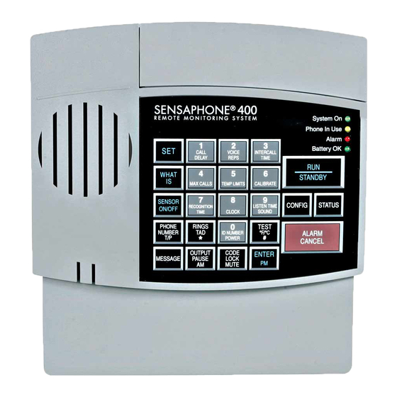
Page 21: Layout
Chapter 1: Introduction Layout 1. programming Keypad 2. power Jack 3. Phone Extension Jack 4. phone Line Jack 5. Speaker 6. Built in Microphone 7. System on LED 8. phone-in-use LED 9. Alarm LED 10. Battery oK LED 11. Battery Compartment 12. -
Page 22: Technical Support
Technical Support If any questions arise upon installation or operation of the Model 400, please contact the Sensaphone Technical Service Department at the number shown below, and have the following information: • Date of Purchase _______________ • Serial number of your Model 400 _________________... -
Page 23: Chapter 2: Installation
2.2 Mounting Flat Mount: place the Model 400 on top of a desk or other horizontal surface. Wall Mount: Mount on a wall with two flathead screws using the keyholes on the back panel of the unit. -
Page 24: Power Surge Protection
Model 400 User’s Manual ® 2.3 Power Surge Protection The Model 400 can be damaged by power surges and lightning through the telephone line and the 120 VAC power supply. Although the Model 400 has built-in surge protection, we recommend that additional protection be obtained for the unit and for any electronic equipment that is attached to your power supply and telephone lines. -
Page 25: Starting The Model 400
In RUn mode, the Model 400 is able to receive incoming calls and to dial out automatically in the event of an alarm on one of the monitored conditions. To enter STANDBY mode, press RUN/ STAnDBY. -
Page 26: Telephone Line
To install the telephone line, plug one end of the modular cord into the “line” jack on the back of the model 400 (as shown) and plug the other end into any standard RJ11 phone outlet. -
Page 27: The Microphone
Chapter 2: Installation (It is not necessary to hook up a telephone for the Model 400 to operate.) This extension jack features Line Seizure which means that it will disconnect the extension jack when the Model 400 needs to make a telephone call. To ensure that the unit has priority over any other device on the line, you must connect all extensions to this jack. -
Page 28: Alert Zones
2.9 Alert Zones Open the input/output wiring door located above the keypad. The Model 400 can monitor up to 4 zones (represented by the numbered terminal screws shown in Figure 2-5, below). ZONES Figure 2-5. -
Page 29: Installing The Sensor
Fasten one lead to the numbered screw and the other lead to C. Tighten both screws. If the zone was not disabled, the Model 400 may recite its “Alarm Exists” message as you connect the sensor. If it does, just press ALARM CAnCEL to stop it. -
Page 30: Multiple Sensors
Continue connecting sensors end-to-end until you have connected all of your sensors. Take the second lead from the last sensor and connect it to the common screw on the Model 400. -
Page 31: Outdoor Wiring
Chapter 2: Installation See Figure 2-8. Multiple n.C. sensors are typically magnetic reed switches to monitor the security of windows and doors. ZONES Multiple normally-closed sensors wired in series (example using Input 2) Alert condition occurs when a switch is opened Figure 2-8. -
Page 32: Disconnecting The Model 400 For Storage Or Seasonal Use
2.13 Disconnecting the Model 400 for Storage or Seasonal Use. If you plan to employ the Model 400 as a seasonal “watchdog” for a few months during the year, you must disconnect all wires from the unit completely to avoid damage to the circuitry when the unit is not in use. -
Page 33: Chapter 3: Quick Start
Chapter 3: Quick Start This section presents a useful guide for first-time programming of the Model 400. Follow instructions for installation before attempting to program the Model 400. Refer to Chapter 2: Installation. 3.1 The Local Keypad Programming is accomplished using the local keypad (shown below, Figure 3-1). -
Page 34: Quick-Start Programming Steps
3.3 Quick-Start Programming Steps Step 1: Set Configuration of Zones The Model 400 will scan the 4 external zones and determine if they are N.O. (normally open), N.C. (normally closed), or Temperature. If external sensors are added, make sure they are in their normal positions before proceeding—refer to Chapter 5,... -
Page 35: Step 2: Set The Id Number
Model 400 is installed. press SET press ID nUMBER. ID NUMBER POWER Using the number keys, enter the digits (up to 16 are permitted) for the ID number. The Model 400 will recite the digits as they are pressed. CALL VOICE INTERCALL DELAY... -
Page 36: Step 4: Set Temperature Limits
TEMP LIMITS LISTEN TIME RECOGNITION CLOCK SOUND TIME ID NUMBER Enter the complete telephone number using the number keys. POWER The Model 400 will recite the digits as they are pressed. CALL VOICE INTERCALL REPS TIME DELAY MAX CALLS TEMP LIMITS... - Page 37 The Model 400 responds: “Enter low temperature limit.” POWER 4. Using the number keys, enter a value for low temperature limit. The Model 400 will recite the digits as they are pressed. If a negative number is required, first press *, then enter the number.
- Page 38 Sensaphone Model 400 User’s Manual ® Using the number keys, enter the value for high temperature limit. The Model 400 will recite the digits as they are pressed. CALL VOICE INTERCALL DELAY REPS TIME MAX CALLS CALIBRATE TEMP LIMITS LISTEN TIME...
-
Page 39: Summary Of The Alarm Dial-Out Process
Chapter 3: Quick Start Summary of the Alarm Dial-Out Process Action—Response Programmable Feature 1 . THE MODEL 400 DETECTS AN • Recognition Time ALERT CONDITION This is the programmed An alert condition is not the same as waiting period to determine a valid alarm—the condition must... - Page 40 Sensaphone Model 400 User’s Manual ®...
-
Page 41: Chapter 4: Communications Programming
The 400’s digital speech recording feature allows you to record custom messages for each of the four Zones and an ID Message. This means that when the 400 calls you during an alarm, you will hear a personalized Voice Message identifying the unit and telling you exactly what alarm condition exists. - Page 42 Sensaphone Model 400 User’s Manual ® To program the ID Message: 1. press the SET key. 2. press the MESSAGE key. The 400 will say “Enter Message number.” MESSAGE 3. Press the ID key (number 0 key). ID NUMBER POWER 4.
- Page 43 Chapter 4: Communications Programming To program the Voice Message for a Zone: 1. press the SET key. 2. press the MESSAGE key. The 400 will say, “Enter Message number.” MESSAGE 3. press the number key for the corresponding Zone. CALL...
-
Page 44: The Unit Id Number
4.2 The Unit ID Number The Unit ID number is the identification number of the Model 400. This number is typically the telephone number where the unit is installed, or it may be designated using any number that best suits your application. -
Page 45: Programming The Id Number
Chapter 4: Communications Programming units in a complex monitoring system. When the Model 400 is called from a remote location, it always begins its message with the identification number: “Hello, this is (Unit ID Number).” 4.2.1 Programming the ID Number To program the ID number: press SET. -
Page 46: Dial-Out Telephone Numbers
Model 400 User’s Manual ® 4.3 Dial-out Telephone Numbers The Model 400 can store up to four 48-digit phone numbers. These are the numbers that will be called during alarm dial-out. In the event of an alarm, the numbers are dialed sequentially, 1 through 4. -
Page 47: Interrogating A Dial-Out Telephone Number
RECOGNITION CLOCK SOUND TIME ID NUMBER Model 400 will recite the corresponding telephone number. If POWER there is no number programmed for a particular key, the unit will respond: “No number.” 4.3.3 Erasing a Telephone Number To erase a telephone number: press SET. -
Page 48: Tone Or Pulse Dialing
ENTER 4.4 Tone or Pulse Dialing The Model 400 can dial out in pulse or Touch Tone™. Select the type of dialing, in either pulse or tone, depending upon the type of service provided by your telephone company. The default is tone. -
Page 49: Special Dialing Keys
These include: pager dialing, Wait for Answer, and Switch to Touch-tones. These functions enable the Sensaphone to send a numeric page, or dial a telephone number + office extension, or combine pulse & touch-tone dialing in the same telephone number. Multiple codes can be used during telephone number programming if required. - Page 50 Code 1 Pager When CODE + 1 is inserted as the first digit of the telephone number, the Model 400 will make a pager call. This means that the unit will expect the call to be answered by a paging service provider, then it will send its ID number (using touch-tones), followed by the digits that identify the zone(s) in alarm.
-
Page 51: Incorporating A Pause
ID NUMBER POWER 5. press pAUSE. The Model 400 will “pause.” OUTPUT PAUSE 6. Enter the complete telephone number using the number keys. The Model 400 will recite the digits as they are pressed. CALL VOICE INTERCALL DELAY REPS TIME... -
Page 52: Incorporating A Pound (#) Or Star (*)
TIME ID NUMBER POWER Position the pound (#) or star (*) within the telephone number where required by pressing the designated keys. The Model 400 will say “pound” or “star” each time the key is pressed. RINGS TEST °F/°C –oR–... -
Page 53: Special Dialing To A Beeper Or
EnTER. The Model 400 will say “Enter.” ENTER 4.5.4 Special Dialing to a Beeper or Pager Your Sensaphone can be programmed to send an alarm message to a numeric beeper/pager. The message will include the Sensaphone’s telephone number (ID number) and the Zone numbers that are in alarm. -
Page 54: Rings Until Answer
4.6 Rings Until Answer Rings Until Answer is the programmed number of times the telephone rings before the Model 400 will answer an incoming call. This can be set from 1 to 15 rings. The default value is 4. 4.6.1 Programming Rings Until Answer To program Rings Until Answer: press SET. -
Page 55: Interrogating Rings Until Answer
Model 400. 4.7.1 TAD Enable/Disable To enable/disable the TAD feature: Press SENSOR ON/OFF. SENSOR ON/OFF Press RINGS/TAD. RINGS The Model 400 will respond: “TAD On.” (If the Model 400 says “TAD Off,” repeat steps 1 and 2 to reactivate TAD.) -
Page 56: Using The Tad Feature
Model 400 User’s Manual ® 4.7.2 Using the TAD Feature Make sure the TAD feature is enabled on the Model 400. (The default setting is disabled, so you must enable it first.) Determine the number of rings your telephone answering device uses to answer the telephone. -
Page 57: No Tad In Use
4.7.3 No TAD In Use If a telephone answering device is not used on the same telephone line as the Model 400, make sure that the TAD feature is disabled, or turned off. only Rings Until Answer programming will determine how incoming calls are answered. For example, if you program Rings Until Answer to 3, incoming calls will be answered in 3 rings. -
Page 58: Interrogating The Listen-In Time
LISTEN TIME SOUND 4.9 Call Delay Call Delay is the programmed length of time the Model 400 waits, following detection of an alarm, before it begins the dial- out sequence. This applies only to the first call. (Delay time between calls is also programmable: refer to Intercall Time, Section 4-12.) -
Page 59: Interrogating Call Delay
The Model 400 will recite the programmed Call Delay. 4.10 Local Voice Mute When the Model 400 dials out to report an alarm, it also audibly recites the alarm message through it’s speaker. The Local Voice Mute command allows you to turn off the speaker at the Model... -
Page 60: Enable/Disable Local Voice Mute
CODE LOCK MUTE The Model 400 will say “Mute On” to indicate that Local Voice Mute is enabled, or “Mute Off” to indicate that it is disabled. 3. Repeat key sequence to switch between enabled or disabled Local Voice Mute. -
Page 61: Interrogating Voice Repetitions
10 seconds to 60 minutes. The default intercall time is 1 minute. If an incoming telephone call is made to the Model 400 during Intercall Time (in between its dialing of subsequent telephone numbers to report an alarm), it will answer the incoming call and... -
Page 62: Programming Intercall Time
The Model 400 recites the digits as you press them. 4. press EnTER. The Model 400 will respond: “Enter seconds.” ENTER 5. Using the number keys, enter the seconds. The Model 400 recites the digits as you press them. CALL... -
Page 63: Interrogating Intercall Time
4.13 Maximum Number of Calls (Max Calls) The Max Calls feature controls the total number of repeated calling attempts by the Model 400 in the event of an alarm. When an alarm occurs, the dial-out process begins, and continues to... -
Page 64: Programming Max Calls
To program Max Calls: 1. press SET. 2. press MAX CALLS. MAX CALLS The Model 400 will respond: “Enter number.” 3. Using the number keys, enter a value. The Model 400 will recite the digits as you press them. VOICE INTERCALL CALL... -
Page 65: The Clock
CLOCK SOUND TIME ID NUMBER POWER 4. If the time is AM, press the AM key. The Model 400 will say “am” If the time is pM , press the pM key. The Model 400 will say “pm.” OUTPUT ENTER... -
Page 66: Interrogating For The Current Time
To interrogate the Model 400 for the current time: 1. press WhAT IS. WHAT 2. press CLoCK. The Model 400 will recite the current time. CLOCK 4.15 The Security Code The Security Code is the last step after setting all other programming parameters for the Model 400. -
Page 67: Unlocking The Keypad
TEMP LIMITS CALIBRATE LISTEN TIME RECOGNITION CLOCK SOUND TIME ID NUMBER POWER 4. press EnTER. ENTER If the correct code is entered, the Model 400 will say “OK.” If the wrong code is entered, the Model 400 will say “Error 2.”... - Page 68 Sensaphone Model 400 User’s Manual ®...
-
Page 69: Chapter 5: Alarm Programming
• Use Exit Delay via Status Report 5.1 Zone Configuration In preparing the Model 400 to sense an alert condition, the zones must be configured as dry contact (either open or closed) or as temperature zones. The default setting for zone 1 is temperature;... -
Page 70: Programming Zone Configuration
1. press STAnDBY to place the Model 400 in Standby mode. STANDBY 2. Wire sensors to the zones to the back of the Model 400 (see Chapter 2, Section 2.10). 3. press RUn. The red light glows when the Model 400 returns to Run mode. -
Page 71: Interrogating Zone Configuration
WHAT 2. press ConFIG. CONFIG The Model 400 will audibly recite the configuration of each zone. 5.2 Enable/Disable Zones This function allows you to enable or disable a zone’s response to an alert condition. An enabled zone will respond to an alert condition and allow dial-out. -
Page 72: Verifying Enabled/Disabled Zone Status
WHAT 2. press STATUS. STATUS The Model 400 audibly recites the current status of every zone. In a Status Report, each zone is first identified by its zone number, followed by a report that specifies parameters currently affecting that zone. If a zone is disabled, the word “Alarm Disabled”... -
Page 73: Programming Zone Recognition Time
The Model 400 responds: “Enter minutes.” POWER 4. Using the number keys, enter the minutes. For example, to set a Recognition Time of five minutes, simply press “5” on the keypad. The Model 400 recites the digits as they are pressed. CALL VOICE INTERCALL... -
Page 74: Interrogating Zone Recognition Time
Sensaphone Model 400 User’s Manual ® 6. Using the number keys, enter the seconds. The Model 400 recites the digits as they are pressed. CALL VOICE INTERCALL DELAY REPS TIME MAX CALLS CALIBRATE TEMP LIMITS LISTEN TIME RECOGNITION CLOCK SOUND... -
Page 75: Establishing High And Low Temperature Limits
The Model 400 responds: “Enter low temperature limit.” POWER 4. Using the number keys, enter a value for low temperature limit. The Model 400 will recite the digits as they are pressed. If a negative number is required, first press *, then enter the number. CALL... -
Page 76: Disabling Alarm Response To High Or Low Temperature
® 5. press EnTER. ENTER The Model 400 responds: “Enter high temperature limit.” 6. Using the number keys, enter the value for high temperature limit. The Model 400 recites the digits as they are pressed. CALL VOICE INTERCALL DELAY REPS... -
Page 77: Interrogating High And Low Temperature Limits
The default temperature scale is Fahrenheit. To change to Celsius: 1. Press SENSOR ON/OFF. SENSOR ON/OFF 2. Press °F / °C. The Model 400 responds: “Degrees Celsius” indicating Celsius scale has replaced Fahrenheit scale. TEST °F/°C 3. To return to Fahrenheit scale, repeat the key sequence. The Model 400 responds: “Degrees Fahrenheit”... -
Page 78: Temperature Calibration
• To program a positive offset number (up to +10 degrees), enter the number on the keypad. The Model 400 recites the digits as they are pressed. • To program a negative offset number (up to –10 degrees), first press *. -
Page 79: Interrogating Temperature Calibration
5.7 Obtaining Current Temperature Current temperature readings for each temperature zone may be accessed at any time. The Model 400 recites the zone number, and the actual temperature detected by the attached sensor, for all zones configured as temperature. To obtain current temperature: 1. -
Page 80: Ac Power Monitoring Enable/Disable
The Model 400 monitors AC power failure. This command enables or disables the power failure detection feature.When enabled, the Model 400 will monitor power and dial out when AC power failure exceeds a programmable span of time (refer to AC Power Failure Recognition Time, Section 5.9). -
Page 81: Programming Power Failure Recognition Time
RECOGNITION TIME 3. press poWER. The Model 400 responds: “Enter minutes.” ID NUMBER POWER 4. Using the number keys, enter the number of minutes. The Model 400 will recite the digits as they are pressed. VOICE INTERCALL CALL DELAY REPS... -
Page 82: Interrogating Power Failure Recognition Time
5.10 Sound Alarm Monitoring This feature allows you to program the level and duration of sound that will cause the Model 400 to respond to an alarm and dial-out. It may be useful to desensitize the Model 400 to sound... -
Page 83: Interrogating Sound Sensitivity
LISTEN TIME RECOGNITION CLOCK SOUND TIME ID NUMBER POWER The Model 400 recites the digits as you press them. 5. press EnTER. The Model 400 responds: “Okay.” ENTER 5.10.2 Interrogating Sound Sensitivity 1. press WhAT IS. WHAT 2. press CALIBRATE. -
Page 84: Interrogating High Sound Alarm Recognition Time
The Model 400 monitors sound through the built-in microphone. When the sound level suddenly exceeds the programmed high sound limit, the Model 400 will respond with an alert condition. The increased sound level must continue throughout the programmed recognition time. The default for high sound alarm is... -
Page 85: Changing Enabled/Disabled High Sound Alarm
The Model 400 is able to suppress and then reset its dial-out function automatically through use of the Status Report. This is especially convenient when an alert condition is created upon exiting a monitored door, and there is no way to cancel from the local keypad. -
Page 86: Designating A Zone Unused
Sensaphone Model 400 User’s Manual ® 2. press STATUS. The Model 400 recites the full Status Report; during this time, you are able to exit the monitored area without tripping an alarm. STATUS 5.13 Designating A Zone As Unused This feature allows you to mark selected Zones, power, or Sound as unused, which will prohibit them from going into alarm and will also leave them out of the status report. -
Page 87: Chapter 6: Acknowledgment, Status Report
• The Status Report on all monitored conditions. • Limited programming. 6.1 Alarm Acknowledgment When the Model 400 dials out with an alarm message, it will request acknowledgment before hanging up. Acknowledgment indicates to the unit that the alarm message has been received. -
Page 88: Callback Acknowledgment
• To enter “555,” press the number (5) key on the Touch-Tone ™ phone keypad three times. The Model 400 will respond: “Alarm Acknowledged.” The Model 400 will hang up and the dial-out sequence, including any further response to the alarm, will be cancelled. -
Page 89: Status Report
• You listen to the message and hang up. • Then you call the Model 400 back on any telephone. You must wait for 10 rings—this signals the Model 400 to answer your telephone call. (Make sure to call back within the programmed setting for Intercall Time—refer to Chapter... -
Page 90: Example: Status Report, No Alarms
Message).” “It is now 12:15 (or the current time).” The Model 400 proceeds with a separate report for each zone. Each zone identifies itself by reciting the zone number and it’s associated voice message. 6.2.1 Example: Status Report, No Alarms Zones 2, 3, and 4 are configured as dry contact and zone 1 is configured as temperature. -
Page 91: Example: Status Report, Existing Alarms
In the example below, all 4 zones are disabled, although zones 1 and 3 are detecting alarms. AC power and Sound Level are also disabled for dial-out. When you call the Model 400 for a Status Report, you hear the following:... -
Page 92: Battery Condition
• “The batteries are low,” if between 7.2 and 8.2 Volts. • “Replace batteries,” if below 7.2 Volts. 6.2.5 Remote Access by Touch-Tone™ Telephone You can issue a number of commands to the 400 remotely using a Touch-Tone telephone. This command mode can be entered ™... - Page 93 • Recite/Set the relay output • Activate the microphone for listen-in • Recite status report NOTE: If a security code is enabled, the 400 will prompt you with “Enter security code.” Enter the four-digit keypad security code plus “#” to enter touch-tone command mode. If entered correctly, the 400 will respond with “oK”...
- Page 94 Sensaphone Model 400 User’s Manual ® Many of the commands use three letters that represent an abbreviation of the selected command. For example, to Set a High limit on Zone 1 you would press S + H + 1 (or in numeric...
- Page 95 Chapter 6: Acknowledgment, Status Report & Remote Access Set and Recite Telephone Numbers The following commands will allow you to program and recite dialout telephone numbers. You may need to use the Special Dialing Codes below. Special Dialing Codes Summary Code 1: numeric pager type Code 2: Wait for answer Code 3: Change to Touch-Tone...
- Page 96 The following command will initiate a status report. Description Touch-Tone Command Recite status report W(9) + S(7) + R(7) Hang-up The following command will make the 400 hang up the telephone line. Description Touch-Tone Command Hang-up the phone line B(2) + Y(9) + E(3)
-
Page 97: Chapter 7: Operation
Chapter 7: Operation After installation and programming is completed, the Model 400 is fully operational. This chapter explains the sequence of events that occur during an alarm dialout to illustrate how the Model 400 operates. 7.1 Alarm Detection, Dial-out and Acknowledgment Generally, an alarm event is structured in the following manner: I. - Page 98 Sensaphone Model 400 User’s Manual ® I.Model 400 Detects a Change at the Sensor Variable Factors Zone Type: (1) An • Model 400 detects a change in the open circuit closes, monitored condition (from the sensor (2) a closed circuit wired to one of the zones).
- Page 99 Activated or not the telephone call is answered. After 10 rings, or if a busy signal is encountered, the Model 400 will hang up, wait the programmed Intercall Time, and proceed to dial the next telephone number. • If no telephone calls are answered, the...
- Page 100 10 seconds, it Normal Code 555 responds: “Alarm acknowledged.” The alarm is considered acknowledged and the dialout concludes. • If the Model 400 does not receive the Tone or Pulse Touch-Tone code within 10 seconds, it Callback recites the following: Acknowledgment: Within Intercall “Error, enter acknowledgement code.”...
- Page 101 Acknowledgment: and call back again within 30 seconds. TAD Enabled The Model 400 will answer on the first ring. It will recite any unacknowledged alarms, then say: “Alarm acknowledged, goodbye.” When the Model 400 hangs up, the alarm is acknowledged and dial-out stops.
-
Page 102: Example: A Dial-Out Telephone Call
The telephone rings at 555-1234, your home number. You answer the telephone and hear the following message: “Hello, this is 555-5674. This is the Sensaphone 400 at John’s Printing Express. It is now 12:30 A . Zone two, back door security sensor, alarm exists, it is not okay.”... -
Page 103: Chapter 8: Controlling The Output
Chapter 8: Controlling the Output The Sensaphone 400 includes a relay output that can be used to control a light, siren, or other device. The output is a Form-C Normally Open/Normally Closed mechanical relay and is rated for up to 30VAC/VDC 1A. A sample wiring diagram is shown... -
Page 104: To Program The Output Mode
8.1.1 To program the Output Mode: 1. Press the SET key. 2. Press the OUTPUT key. OUTPUT PAUSE The 400 will say “Enter output mode.” 3. Using the number keys, enter a value for the output mode. INTERCALL CALL VOICE... -
Page 105: To Play Back The Programmed Output Mode
4. Press the ENTER key. ENTER The 400 will say “OK” and recite a description of the mode selected, such as “Automatic on Zone 1” or “Manual.” Note that when Mode * is selected, the 400 will simply say “Automatic on Alarm,”... -
Page 106: Typical Applications
Prior to your arrival at your cottage or cabin, you can remotely use your Sensaphone 400 to raise the thermostat and increase the heat. - Page 107 Follow the manufacturer’s instructions for installing the thermostat. The Model 400 will need to be wired to the thermostat to control it. For a visually appealing installation you may want to locate the Sensaphone close to your heater so that the cable follows the same path as the one from your heater to the thermostat.
-
Page 108: Keypad Commands
Controlling the Thermostat The operating mode of the thermostat (normal/vacation) can be controlled at the Model 400 keypad or remotely via Touch-Tone comands. Both methods are described below: Keypad commands: 1) To enable Vacation Mode, press the [SENSOR ON/OFF] key, then the [OUTPUT] key. -
Page 109: Dual Thermostat Control
Call the Sensaphone. When the unit answers, it will begin reciting a status report. At any time during the call, press a Touch-Tone. The unit will respond with “OK.” The Sensaphone is now ready to accept Touch-Tone commands. 1) To enable Vacation Mode, press SRO (776). The unit will respond by saying “ON”... - Page 110 By connecting these two thermostats together in a parallel fashion, and by passing the low voltage supply through the Sensaphone (See Figure 1), you can remotely or locally decide which thermostat is in control of your furnace. It is recommended that the “away” thermostat be connected to the NC (Normally Closed) terminal while the “home”...
-
Page 111: Controlling Lights Or Other Devices
Module Module Figure 2: X10 Lighting Control Setup Sensaphone supports these devices through use of the popular X10 Powerflash relay interface. To learn more about this technology, consult X10 products on the web at www.x10.com or visit your local electronics shop such as Radio Shack. - Page 112 Sensaphone Model 400 User’s Manual ®...
-
Page 113: Appendix A: Weekly Testing Procedure
Appendix A: Weekly Testing Procedure We recommend that you test your Sensaphone weekly to be sure it is functioning properly. This will ensure that when a problem arises the Sensaphone will be ready to alert the appropriate personnel. There are several tests that can be performed: 1) Call the unit and listen to the Status Report. - Page 114 Allow the unit to dial all programmed telephone numbers. 5) Keep a log of your tests, noting the date and whether the 400 passed in each category tested. An example of such a log is shown below. (See “Test Log” at the end of this manual.)
-
Page 115: Appendix B: Troubleshooting
Most problems with the Model 400 are easy to identify and quickly corrected, and are found under the following general headings: •... - Page 116 Sensaphone Model 400 User’s Manual ®...
- Page 117 Appendix B: Troubleshooting...
- Page 118 Sensaphone Model 400 User’s Manual ®...
- Page 119 Appendix B: Troubleshooting...
- Page 120 Sensaphone Model 400 User’s Manual ®...
- Page 121 Appendix B: Troubleshooting...
- Page 122 Sensaphone Model 400 User’s Manual ®...
- Page 123 Appendix B: Troubleshooting...
- Page 124 Sensaphone Model 400 User’s Manual ®...
-
Page 125: Appendix C: 400 Quick Reference
Appendix C: 400 QUICK REFERENCE Parameter Description Key Sequence* Range Default Call Delay Time delay until [SET] or [WHAT IS] Min: 00:00 00:30 first call is made + [CALL DELAY] Max 60:00 (min:sec) (min:sec) Voice Reps Number of times alarm... - Page 126 Sensaphone Model 400 User’s Manual ® Range/ Parameter Description Key Sequence* Response Default Telephone Answering [SENSOR ON/OFF] Enable / Disable Disabled + [TAD] Device Compatibility ID Number Sets the unit’s telephone [SET] + [ID NUMBER] 0-16 number Dialout Test Permits testing of dialout...
- Page 127 Appendix C: Quick Reference Parameter Description Key Sequence Response Default Speaker Mute Turns off the speaker during [SENSOR ON/OFF] On or Off + [MUTE] alarm conditions Designating A Removes zone from status [SENSOR ON/OFF] + On or Off and alarm reports Zone Unused [SET] + [zone #] Zone Enable/...
- Page 128 Sensaphone Model 400 User’s Manual ®...
-
Page 129: Appendix D: Accessories
Commercial or industrial electrical supply houses can provide devices to monitor virtually any condition. For further information, contact Sensaphone Customer Service at 610-558-2700. PART # SENSOR / SWITCH... - Page 130 Sensaphone Model 400 User’s Manual ®...
-
Page 131: Appendix E: Specifications
Extension RJ11 Jack w/ Line Seizure: For connecting other devices on the same telephone line, devices connected to this jack are disconnected in the event that the 400 must dial out for an alarm. Phone Line Protection: Metal Oxide Varistor & self-resetting... -
Page 132: Relay Output
Sensaphone Model 400 User’s Manual ® Alarm: Off when no alarm exists. Blinks when an unacknowleged alarm exists. On steady when an acknowledged alarm exists Battery Ok: on steady when the battery is in good condition. Blinks when the battery is low. off when the battery must be replaced. -
Page 133: Appendix F: Returning The Unit For Repair
Appendix F: Returning the Unit for Repair In the event that the Model 400 does not function properly, we suggest that you do the following: 1) Record your observations regarding the Model 400’s malfunction. 2) Call the Technical Service Department at 815-436-4440 prior to sending the unit to us for repair. - Page 134 Sensaphone Model 400 User’s Manual ®...
-
Page 135: Appendix G: Test Log
Appendix G: Test Log... - Page 136 Appendix G: Specifications...
Need help?
Do you have a question about the 400 and is the answer not in the manual?
Questions and answers