Table of Contents
Advertisement
Advertisement
Table of Contents

Related Manuals for Husqvarna 67521HVE


Summary of Contents for Husqvarna 67521HVE
- Page 1 67521HVE Owner’s Manual 532 19 67-14 01.13.05 BY Printed in U.S.A.
-
Page 2: General Operation
Safe Operation Practices for Walk-Behind Mowers IMPORTANT: THIS CUTTING MACHINE IS CAPABLE OF AMPUTATING HANDS AND FEET AND THROW ING OBJECTS. FAILURE TO OBSERVE THE FOLLOWING SAFETY INSTRUCTIONS COULD RESULT IN SERIOUS INJURY OR DEATH. Look for this symbol to point out im- por tant safety precautions. -
Page 3: Table Of Contents
(motor) running. Disconnect spark plug wire, and keep WARNING: This lawn mower is equipped with an internal com bus tion engine and should not be used on or near any un im proved forest-covered, brush-covered or grass-cov ered land unless the engine’s exhaust system is equipped with a spark arrester meeting applicable local or state laws (if any). -
Page 4: Assembly
IMPORTANT: THIS LAWN MOWER IS SHIPPED WITH- OUT OIL OR GASOLINE IN THE ENGINE. Your new lawn mower has been as sem bled at the factory with the ex cep tion of those parts left unassembled for ship- ping purposes. All parts such as nuts, washers, bolts, etc., necessary to com plete the as sem bly have been placed in the parts bag. -
Page 5: Assembly
BINDINGS FIG. 4 ASSEMBLY TO INSTALL ATTACHMENTS Your lawn mower was shipped ready to be used as a mulcher. To convert mower to bagging or discharging, see “TO CON VERT MOWER” in the Operation section of this man u al. -
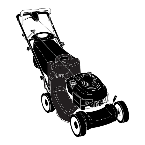
Page 6: Know Your Lawn Mower
KNOW YOUR LAWN MOWER READ THIS OWNER'S MANUAL AND SAFETY RULES BEFORE OPERATING YOUR LAWN MOWER. Compare the illustrations with your lawn mower to familiarize yourself with the location of various controls and adjustments. Save this manual for future reference. -
Page 7: Engine Zone Control
The operation of any lawn mower can result in foreign objects thrown into the eyes, which can result in severe eye damage. Always wear safety glasses or eye shields while operating your lawn mower or performing any adjustments or repairs. We recommend standard safety glasses or a wide vision safety mask over spectacles. - Page 8 • Open mulcher door and install front of side dis charge defl ector beneath it as shown. • Secure rear of side discharge defl ector to lawn mower housing with knob. OPERATION • Mower is now ready for side discharging operation.
-
Page 9: Before Starting Engine
OPEN FIG. 11 2. Remove grass catcher with clippings from lawn mower using both front and rear handles. 3. Empty clippings from bag using rear handle and strap. The weight of the grass will open the door. -
Page 10: To Stop/Start Engine
• For best results, adjust the lawn mower cutting height so that the lawn mower cuts off only the top one-third of the grass blades (See Fig. 14). If the lawn is over- grown it will be necessary to raise the height of cut to reduce pushing effort and to keep from overloading the engine and leaving clumps of mulched grass. -
Page 11: General Recommendations
Use a scraper to clean under deck GENERAL RECOMMENDATIONS The warranty on this lawn mower does not cover items that have been subjected to operator abuse or negli- gence. To receive full value from the warranty, opera- tor must maintain mower as instructed in this manual. -
Page 12: Lawn Mower
1. Disconnect spark plug wire from spark plug and place wire where it cannot come in contact with plug. 2. Turn lawn mower on its side. Make sure air fi lter and carburetor are up. 3. Use a wood block between blade and mower hous ing to prevent blade from turning when re mov ing blade bolt. -
Page 13: To Change Engine Oil
Change the oil after every 25 hours of operation or at least once a year if the lawn mower is not used for 25 hours in one year. Check the crankcase oil level before starting the engine and after each fi ve (5) hours of continuous use. Tighten oil plug securely each time you check the oil level. -
Page 14: Service And Adjustments
4. Pivot idler arm assembly to slacken drive belt, then remove drive belt from drive pulley, belt keepers and idler arm. 5. Turn lawn mower on its side. Make sure air fi lter and carburetor are up. 6. Remove screw securing debris shield. Note that the debris shield has a tab which fi... -
Page 15: Storage
3. Align opposite side of handle with same positioning hole and secure with bolt and knob. Immediately prepare your lawn mower for storage at the end of the season or if the unit will not be used for 30 days or more. LAWN MOWER When lawn mower is to be stored for a period of time, clean it thoroughly, remove all dirt, grease, leaves, etc. -
Page 16: Engine Fuel System
HANDLE (See Figs. 23 and 24) You can fold your lawn mower handle for storage. 1. Loosen the two (2) handle knobs on sides of the upper handle and allow handle to fold down to the rear. 2. Remove the two (2) handle knobs and carriage bolts on sides of the lower handle and pivot entire handle as sem bly forward and allow it to rest on mower. -
Page 17: Troubleshooting Points
1. Depress control bar to upper handle before pulling starter rope. 2. Contact a qualifi ed service center. 3. Replace blade adapter. 4. Move lawn mower to cut grass or other hard surface before starting. 1. Raise cutting height. 2. Replace blade. -
Page 18: Repair Parts
ROTARY LAWN MOWER - - MODEL NUMBER 67521HVE (96143001100) - PRODUCT NUMBER 961 43 00-11... - Page 19 Adjustment Bracket, Lower Handle, LH IMPORTANT: Use only Original Equipment Manufacturer (O.E.M.) replacement parts. Failure to do so could be hazardous, damage your lawn mower and void your warranty. NOTE: All component dimensions given in U.S. inches. 1 inch = 25.4 mm.
- Page 20 ROTARY LAWN MOWER - - MODEL NUMBER 67521HVE (96143001100) - PRODUCT NUMBER 961 43 00-11...
- Page 21 Bolt, Hex Head, Shoulder IMPORTANT: Use only Original Equipment Manufacturer (O.E.M.) replacement parts. Failure to do so could be hazardous, damage your lawn mower and void your warranty. NOTE: All component dimensions given in U.S. inches. 1 inch = 25.4 mm.
- Page 22 GEAR CASE ASSEMBLY - - PART NUMBER 532 18 82-94 NOTE: All component dimensions given in U.S. inches. 1 inch = 25.4 mm. IMPORTANT: Use only Original Equipment Manu- facturer (O.E.M.) replacement parts. Failure to do so could be hazardous, damage your lawn mower and void your warranty. PART...
-
Page 23: Service Notes
SERVICE NOTES...
Need help?
Do you have a question about the 67521HVE and is the answer not in the manual?
Questions and answers