Advertisement
Advertisement
Table of Contents

Related Manuals for Vintage Keeper Tuscany 110


Summary of Contents for Vintage Keeper Tuscany 110
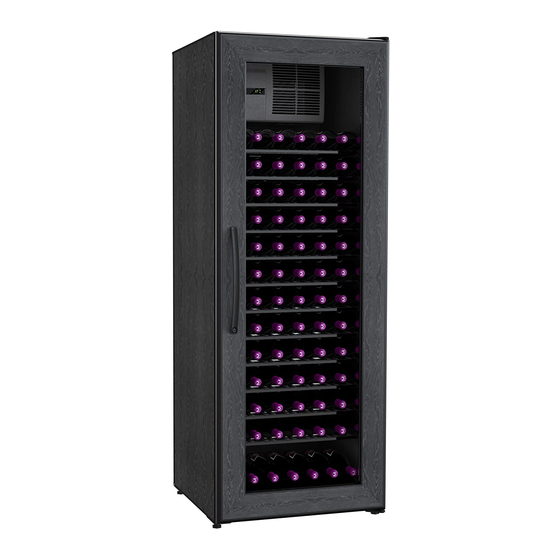
- Page 1 TUSCANY 1 1 0 2 2 0 Plus WINE CELLAR ASSEMBLY & OPERATION MANUAL...
- Page 3 You must monitor your unit DAILY. If unit is in “Alarm”, unplug the unit immediately. Always check for any water (condensate) leaks. Vintage Keeper will not be liable or responsible for incidental or consequential damages. (See Warranty). Place unit in a clean area and allow access to the exterior surfaces for periodic vacuuming of the condensor coil.
-
Page 4: Hardware Kit
HARDWARE KIT Cam Cap Phillips Bolt Hex bolt x 20 (x24)* x 14 Hex wrench Cam Pin x 20 (x24)* x 20 (x24)* Hinge Washer Rubber Grommet Panel Insulation Strip *NOTE : Hardware quantities for Model 220 are indicated in parenthesis. -
Page 5: Step 1 : Panel Preparation
STEP 1 : PANEL PREPARATION CAUTION : 1. Watch for sharp staples on boxes. 2. DO NOT STEP ON PANELS 3. The manual will give a recommended order to open boxes, it saves space and time. PANEL EDGE Open Box V1. Install INSULATION STRIP to Back, Top, and Bottom Panels. -
Page 6: Step 2 : Cabinet Assembly
STEP 2 : CABINET ASSEMBLY Attach Top and Bottom to Back by CAREFULLY aligning edge holes over Cam Pins and gently push together to avoid damaging cam pins. DO NOT BANG OR SLAP PANELS TOGETHER!!! Insert Cam and make sure Arrow points to outside edge. - Page 7 STEP 2 : CABINET ASSEMBLY CONTINUED Open Box V5 or V2. Insert Cam Pins (F) into SIDE PANEL’S pre drilled holes both sides. Attach SIDES to Back/Bottom/Top by Carefully aligning edge holes over Cam Pins and gently push together to avoid damaging cam pins.
- Page 8 STEP 3 : HINGE,BASE AND LEGS INSTALLATION Fasten one HINGE (G) to the SIDE of the cabinet NOTE : Hinge can be on either side of the cabinet. Install four LEGS (H) into BASES fully in. Fasten FRONT BASE the BOTTOM of the cabinet (FRONT BASE has to be set with end tabs away from front edge)
- Page 9 STEP 4 : SHELVES Open box V4 Hook SHELVES into hangers starting from the bottom of cabinet PRESS BOTTOM HINT : Snap SHELVES into hangers on one side Push the SHELVES down to snap into opposite side hangers...
- Page 10 STEP 5 : COOLING UNIT INSTALLATION ~10~...
- Page 11 STEP 5 : COOLING UNIT INSTALLATION CONTINUED Slide unit into the back opening and HOOK lock WING over the LEFT BOLT and GROM- MET from (STEP 1). Top View Screw in Right Bolt into top panel until grommet touches top. DO NOT com- press Grommet.
- Page 12 STEP 5 : COOLING UNIT INSTALLATION CONTINUED Insert Drain Cup by angling the Drain Cup inserting back tab first then push in front lip to allow tab in. Insert Air Deflector to back of cooling unit. Install bottom Tab first. ~12~...
- Page 13 STEP 5 : COOLING UNIT INSTALLATION CONTINUED NOTE: If unit is operated according to specifications overflows will not occur. Excess condensation is only caused by extreme conditions. Unit will shut off at 72 °F and will restart when temperature drops or unit is repluged. (In this case insert hose to drain hole, cut to appropriate length.) CAUTION : Maximum Total Load: 1A...
- Page 14 STEP 6 : LIGHT AND LIGHT COVER INSTALLATION LIGHT CLIPS Fasten into mounting holes predrilled on front edge of TOP panel Snap LIGHT in LIGHT CLIPS Plug small end of power cord into socket on side of light Snap LIGHTCOVER over the LIGHT HINT: To hide excess light cord, tuck into top space of cooling...
-
Page 15: Step 7 : Door Installation
STEP 7 : DOOR INSTALLATION Open box V3 Place WASHER (I) on BOTTOM HINGE (G) Insert DOOR onto BOTTOM HINGE (G) Install TOP HINGE (G) with HEX BOLTS (C) NOTE : Adjust final position of the door before tightening the bolts ~15~... -
Page 16: Controller Operation
CONTROLS : PLUG IT IN and ENJOY! (wait one minute) FEATURES: - Default SET temperature 57º F/14º C (ideal for wine storage). DISPLAY: - Calibration option of the temperature sensor. KEYS - SET temperature range 52ºF-72ºF. - Digital temperature sensor. - Dual display Fº/Cº. - Page 17 MAXIMUM CAPACITIES AND LOADING TIPS Maximum capacities and sample loading arrangements for Vintage Keeper Tuscany wine cellars are illustrated below. Note the variations in shelf height, to accommodate the widest variety of bottle types and sizes. Standard Burgundy and Bordeaux bottles are best arranged with necks facing out;...
-
Page 18: Troubleshooting Guide
TROUBLE SHOOTING GUIDE Although each Vintage Keeper cooling unit has been carefully tested at every stage of manufacture, occasional problems arise, the majority of which are due to rough or careless handling during shipping or installation. Other problems may derive from improper cabinet assembly, power interruption or surge, low line voltage (less than 105V), or failure to clean the unit regularly (see illustration below). - Page 19 (credit card authorization), we will promptly ship a replacement unit. The replacement may be a unit that has been reconditioned by VINTAGE KEEPER INC. The unit that needs service must be packed and returned to us, shipping prepaid.
- Page 20 TUSCANY 1 1 0 2 2 0 Plus WINE CELLAR 5648 McAdam Rd., Mississauga ON CAN L4Z 1T2 Phone : 905.501.8582 Fax : 905.501.0889 Toll free: 1.888.274.8813 customerservice@vintagekeeper.com www.vintagekeeper.com ~20~...
Need help?
Do you have a question about the Tuscany 110 and is the answer not in the manual?
Questions and answers