
Related Manuals for Husqvarna 13 H


Summary of Contents for Husqvarna 13 H
- Page 1 Rider 11/13 H Operator´s manual Please read these instructions carefully and make sure you understand them before using the machine. 101 90 52-26...
- Page 2 Svenska –...
-
Page 3: Table Of Contents
Rider 11 and Rider 13 H Explanation of symbols ... 2 Safety instructions ... 3 General use ... 3 Driving on slopes ... 4 Children ... 5 Maintenance ... 5 Presentation ... 7 Location of the controls ... 7 Throttle/Choke lever ... 8 Speed limiter ... -
Page 4: Explanation Of Symbols
EXPLANATION OF SYMBOLS These symbols are on the machine and in the operator’s manual. Study them carefully so that you know what they mean. Reverse Neutral Fast Oil pressure Cutting height Use eye and Clutch in hearing protection Soundlevel Warning! Rotating blades. -
Page 5: Safety Instructions
SAFETY INSTRUCTIONS These instructions are for your safety. Read them carefully. This symbol implies that important safety rules are applicable. This is for your safety and the operating reliability of the machine. General use: • Make yourself familiar with the controls and how to stop quickly. -
Page 6: Driving On Slopes
SAFETY INSTRUCTIONS • Watch out for traffic when working close to a road, or crossing one. • Be careful when rounding a fixed object so that the blades do not hit it. Never drive intentionally over a foreign object. • The machine is heavy and can cause very severe crush injuries. -
Page 7: Children
SAFETY INSTRUCTIONS • Do not cut close to edges, ditches or banks. The machine can suddenly tip over if a wheel goes over the edge of a drop or a ditch, or if a bank gives way. • Do not cut wet grass. It is slippery and the tyres can loose their grip so that the machine slides. - Page 8 SAFETY INSTRUCTIONS • Avoid overfilling. If fuel has been spilt on the machine wipe it up and wait until it has evapor- ated before starting the engine. If fuel is spilt on clothes, change them. • Be extra careful when handling battery acid. Spilling acid on the skin can cause severe burn injuries.
-
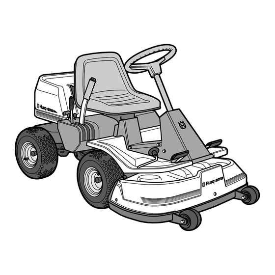
Page 9: Presentation
Rider 11 has an in-line gearbox with five forward gears and one reverse gear. On the Rider 13 H the power transmission from the engine is handled by a hydrostatic gearbox which enables stepless variation of the speed. -
Page 10: Throttle/Choke Lever
PRESENTATION Throttle and Choke lever Rider 13 H The engine speed is adjusted with the throttle control, and thereby also the rotation speed of the blades. The control is also used to activate the choke function. When the choke is used the engine receives a richer mixture of fuel and air, which simplifies cold start. - Page 11 PRESENTATION Throttle and Choke lever Rider 11 The engine speed is adjusted with the throttle control, and thereby also the rotation speed of the blades. The control is also used to activate the choke function. When the choke is used the engine receives a richer mixture of fuel and air, which simplifies cold start.
-
Page 12: Cutting Unit
PRESENTATION Cutting unit Rider 11 and Rider 13 H have a cutting unit with rear ejection, i.e. the grass cuttings are thrown out behind the cutting unit. Lift lever for cutting unit The lift lever is used to set the cutting unit in trans- port or cutting position. -
Page 13: Seat
Seat The seat has a jointed attachment on the front edge and can be tipped forward. The seat can also be adjusted lengthways. Release the wheels under the seat and adjust it forwards or backwards to the required position. Lock the adjustment with the wheels. Fuelling The engine should be run on 85 octane unleaded petrol/gasoline (not oil mixed). -
Page 14: Driving
The parking brake lock disconnects automati- cally when the brake pedal is pressed down. The drawing shows a Rider 13 H. On the Rider 11 the brake pedal and lock button are on the right side. 3. For Rider 11: Set the gear lever to position “N”... - Page 15 Cold engine: 4. Push the throttle control to position 3 (choke position). In this position the engine receives a richer mixture so that the engine starts more easily. Warm engine: 5. Set the throttle control midway between position 1 and 2. 6.
-
Page 16: Driving The Machine
Driving the machine 1. Release the parking brake by pressing down the brake pedal. The drawing shows a Rider 13 H. 2. For Rider 13 H Carefully press down one of the pedals until the correct speed is reached. -
Page 17: Cutting Tips
3. Select the required cutting height (1-9) with the cutting height lever. To obtain a uniform cutting height it is important that the tyre pressures are equal on both front wheels (60 kPa). 4. Push in the lock button on the lift lever and lower down the cutting unit. -
Page 18: Stopping The Engine
“N”. Turn the ignition key to the “STOP” position. Rider 13 H: Pull back the throttle lever and turn the ignition key to the “STOP” position. 3. When the rider mower is stationary, hold down the parking brake and push in the lock button. -
Page 19: Service
Check the tyre pressures (60 kPa) Change the engine oil Adjust the brakes – Rider 11 Check the V-belts Check the hydrostat’s cooling fins – Rider 13 H Check the transmission’s oil level Adjust the brakes – Rider 13 H Lubricate joints and shafts Check and adjust the throttle wire Clean the engine’s and hydrostat’s cooling flanges... -
Page 20: Dismantling Of The Machine Hoods
Release the screws in the front hood (3) and lift off the hood. Right-hand fender Remove the screws (2 and 3) from the fender. On the Rider 13 H the footplate (1) must also be re- moved. Left-hand fender Release the screws in the fender and lift off the fender. -
Page 21: Checking The Engine's Oil Level
MAINTENANCE Check the engine’s oil level Check the oil level in the engine when the machine is horizontal. Raise the engine cover as described on page 18. Release the dip stick and pull out. Wipe off the oil and insert again. The dip stick must be fully screwed down. -
Page 22: Checking And Adjusting The Steering Wires
Checking and adjustment of the steering wires The steering is controlled by means of wires. These can in time become slack, which implies that the adjustment of the steering becomes altered. Check and adjust the steering as follows: 1. Dismantle the frame-plate by releasing the screws (two on each side). -
Page 23: Adjusting The Brake
1 mm. 3. Tighten the lock nuts (1) after adjustment. Adjusting the brake Rider 13 H The brake is adjusted as follows: 1. Release the lock nuts (1). 2. Tension the wire with the adjusting screw (2) until all the play in the wire is taken up. -
Page 24: Checking The Transmission's Oil Level
Check the transmission’s oil level Rider 13 H 1. Check the transmission’s oil level by removing the transmission cover. Release the two screws (one of each side) and lift off the transmission cover. 2. Unscrew the oil cap and check that the oil level lies between the markings on the dip stick. -
Page 25: Replacing The Air Filter
Replacing the air filter If the engine seems to lack power or goes irregu- larly the reason may be that the air filter is clogged. It is therefore important to replace the air filter at regular intervals (see maintenance schedule on page 17 for correct service interval). -
Page 26: Checking The Parallelism Of The Cutting Unit
Checking the cutting unit’s parallelism Check the parallelism of the cutting unit as follows: 1. Place the machine on a level surface. 2. Measure the distance from the ground to the edge of the unit, at the front and back of the hood. -
Page 27: Dismantling The Cutting Unit
Dismantling the cutting unit The cutting unit can be released from the machine for cleaning or checking of the blades and screws. Dismantle the cutting unit as follows: 1. Dismantle the front hood and right-hand and left- hand fenders as described on page 18. 2. -
Page 28: Checking The Blades
Checking the blades To achieve the best mowing results it is important that the blades are undamaged and well-sharpened. Check that the blades’ attachment screws are tight. IMPORTANT INFORMATION Replacing or sharpening the blades should be conducted by an authorised service workshop. -
Page 29: Changing The Oil
Changing the oil The oil should be changed for the first time after 5 hours of running time. Thereafter it should be changed every 25 hours of running time. WARNING! Engine oil can be very hot if it is drained off directly after the engine is stopped. -
Page 30: General Lubrication
MAINTENANCE Lubrication The following two lubrication points should be regularly lubricated with high quality graphite grease. With daily use lubrication should be conducted twice a week. General lubrication All joints and bearings are lubricated on manufac- ture with molybdenum sulphide grease. Re-grease with same type of grease. -
Page 31: Checking And Adjustment Of Throttle Wire
Checking and adjustment of the throttle wire If the engine does not respond as it should do when the throttle lever is moved or if the top speed is not reached, the throttle wire may need adjusting. 1. Release the clamping screw (see arrow) and push the throttle control to full throttle position. -
Page 32: Trouble Shooting Schedule
TROUBLE SHOOTING SCHEDULE Problem Engine will not start. Starter does not pull round engine. Engine does not run smoothly. Engine seems to have no power. Engine overheats. Battery does not charge. Machine vibrates. Uneven mowing. – English Procedure • Fuel tank empty. •... -
Page 33: Storage
Winter storage At the end of the season the machine should immediately be put in order for storage, also if it is going to stand idle for more than 30 days. Fuel which is left to stand for long periods (30 days or more) can leave tacky deposits which can block the carburettor and interfere with the engine. -
Page 34: Technical Data
Note that no legal claims are valid on the basis of information in this manual. Use only genuine parts for repairs. The warranty is not valid if non genuine parts are used. – English ´*3%6¶6`¨ TECHNICAL DATA Rider 13 H 2000 mm 960 mm 1060 mm 225 kg... -
Page 35: Eu Declaration Of Conformity
We, Husqvarna AB, S-561 82 Huskvarna, Sweden, tel. +46 36-146500, declare under sole responsibility that the rider mowers Husqvarna Rider 11/13 H from 1998’s serial numbers and onwards (the year is clearly stated in plain text on the type plate with subsequent serial number), is in conformity with the following standards or other normative documents following the provisions in the COUNCIL’S DIRECTIVES:... - Page 36 ´*3%6¶6`¨ 1999W43...
Need help?
Do you have a question about the 13 H and is the answer not in the manual?
Questions and answers