Bosch MIC Series Installation Manual
Mic power supply units
Hide thumbs
Also See for MIC Series:
- Installation manual (46 pages) ,
- Tech note (20 pages) ,
- Installation manual (8 pages)
Table of Contents
Advertisement
Quick Links
Download this manual
See also:
Installation Manual
Advertisement
Table of Contents

Related Manuals for Bosch MIC Series


Summary of Contents for Bosch MIC Series
- Page 1 MIC Power Supply Units (Standard) MIC Series Installation Manual...
-
Page 3: Conventions In This Manual
NOTICE! This symbol indicates information or a company policy that relates directly or indirectly to the safety of personnel or protection of property. Bosch Security Systems, Inc. Installation Manual F.01U.265.804 | 1.3 | 2012.03... -
Page 4: Important Safety Instructions
13. Attachments, changes or modifications - Only use attachments/accessories specified by the manufacturer. Any change or modification of the equipment, not expressly approved by Bosch, could void the warranty or, in the case of an authorization agreement, authority to operate the equipment. -
Page 5: Important Notices
Disposal - Your Bosch product was developed and manufactured with high-quality material and components that can be recycled and reused. This symbol means that electronic and electrical appliances, which have reached the end of their working life, must be collected and disposed of separately from household waste material. - Page 6 Cet appareil génère, utilise et émet de l'énergie de radiofréquences et peut, en cas d'installation ou d'utilisation non conforme aux instructions, engendrer des interférences nuisibles au F.01U.265.804 | 1.3 | 2012.03 Installation Manual Bosch Security Systems, Inc.
- Page 7 Notice of Regulatory Compliance This product complies with the following EC directives: – EMC Directive (89/336/EC as amended) – LV Directive (73/23/EC) – RoHS (Restriction of Hazardous Substances) 2002/95/ECEMC, CISPRA-B and CTIC Bosch Security Systems, Inc. Installation Manual F.01U.265.804 | 1.3 | 2012.03...
-
Page 8: Customer Support And Service
| Safety MIC PSU Standard Customer Support and Service If this unit needs service, contact the nearest Bosch Security Systems Service Center for authorization to return and shipping instructions. Service Centers Repair Center- Telephone: 800-566-2283 Fax: 800-366-1329 E-mail: repair@us.bosch.com... -
Page 9: Installation
A provision for driving various optional interface cards mounted internally to the MIC power supply enclosure (for example, an 8-input alarm card (MIC-ALM)) – A provision for a signal interface card (MIC-BP4) to connect telemetry to Bosch Biphase equipment –... -
Page 10: Earth Link On The Pcb
Replace only with the same type and rating of fuse for continued protection against the risk of fire, damage or injury. Fitting fuses other than those described above invalidates the product warranty and may result in damage to the product or injury to the installer. F.01U.265.804 | 1.3 | 2012.03 Installation Manual Bosch Security Systems, Inc. -
Page 11: Mic Power Supply Units (Psus) For Non-Ir Mic Cameras
Plug in Earth Link Earth Link Fuse 2 - Primary protection Fuse 1 - MIC camera protection Fuse 3 - Heater protection 1 Fuse 5 - Heater protection 2 Bosch Security Systems, Inc. Installation Manual F.01U.265.804 | 1.3 | 2012.03... - Page 12 Earth Link Fuse 2 - Primary protection Fuse 4 - washer drive Fuse 3 - IR lamps Fuse 1 - MIC camera protection Fuse 5 - MIC camera protection F.01U.265.804 | 1.3 | 2012.03 Installation Manual Bosch Security Systems, Inc.
-
Page 13: Installation Instructions
® Electrical Code (NEC)), Canadian Electrical Code, Part I (also called CE Code or CSA C22.1), and all applicable local codes. Bosch Security Systems, Inc. accepts no liability for any damages or losses caused by incorrect or improper installation. DANGER! –... - Page 14 Select the mounting position of the MIC PSU so that the PSU cannot be interfered with either intentionally or accidentally. Bosch recommends using a lockable cabinet. Locate the four (4) mounting holes of the power supply enclosure. (Figure 2.3 displays one of the holes.) See the dimensional drawing in the appendix for hole locations.
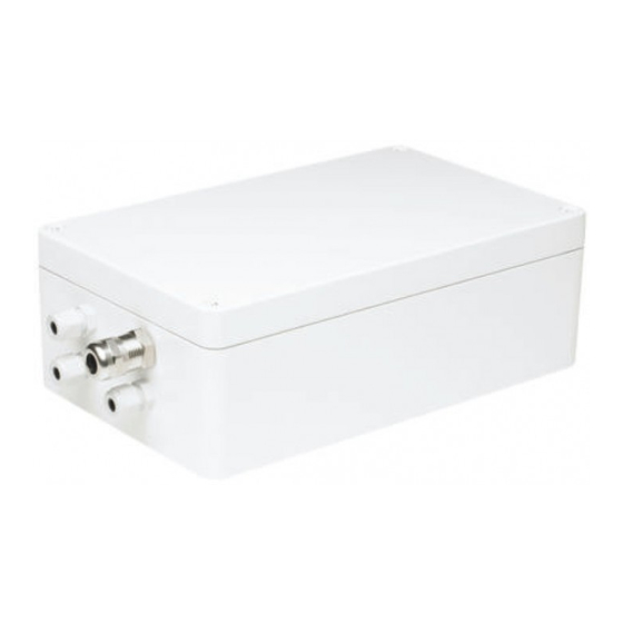
- Page 15 17. Feed the unconnected end of the shielded composite cable through the top-right M16 cable gland (item 2, Figure 2.6). Figure 2.6 MIC PSU Enclosure, with cable glands identified Bosch Security Systems, Inc. Installation Manual F.01U.265.804 | 1.3 | 2012.03...
- Page 16 [Optional] Auxiliary Connection (heater/IR) Grey HD7-1 Video Switched Output to Control Room Core [Only for MIC612 composite cable] (Black) HD7-2 Video Out (Signal Ground) Screen [Only for MIC612 composite cable] (Black) F.01U.265.804 | 1.3 | 2012.03 Installation Manual Bosch Security Systems, Inc.
- Page 17 28. On MIC IR power supplies, connect alarm input cables to terminal block HD2, as per the table below: Signal Pin Number Alarm 1 1 Alarm 2 3 Alarm 3 5 Alarm 4 7 Bosch Security Systems, Inc. Installation Manual F.01U.265.804 | 1.3 | 2012.03...
- Page 18 LED 2 18 VAC power on to camera LED 4 Power on for optional heater LED 3 18 VAC power on camera LED 5 Power on for optional heater F.01U.265.804 | 1.3 | 2012.03 Installation Manual Bosch Security Systems, Inc.
- Page 19 MIC PSU Standard Installation | en Figure 2.8 MIC Series IR power supply LED positions Number LED Description MIC IR models LED 1 , Indicates that 18 VAC is available from the power supply and that LED 2 the supply fuses are intact.
-
Page 20: Commissioning The Camera With Heater Option Fitted
The heaters are thermostatically controlled and will automatically turn on at +5 °C (+41 °F) and turn off at +15 °C (+59 °F). Check all connections. Close the PSU enclosure. 10. Reconnect the power supply to the power source. F.01U.265.804 | 1.3 | 2012.03 Installation Manual Bosch Security Systems, Inc. -
Page 21: Dimensional Drawings
MIC PSU Standard Dimensional Drawings | en Dimensional Drawings 288 mm (11.3 in.) 260 mm (10.2 in.) 240 mm (9.5 in.) Bosch Security Systems, Inc. Installation Manual F.01U.265.804 | 1.3 | 2012.03... - Page 22 | Dimensional Drawings MIC PSU Standard F.01U.265.804 | 1.3 | 2012.03 Installation Manual Bosch Security Systems, Inc.
- Page 24 Bosch Security Systems, Inc. 850 Greenfield Road Lancaster, PA 17601 U.S.A. www.boschsecurity.com © Bosch Security Systems, Inc., 2011...
Need help?
Do you have a question about the MIC Series and is the answer not in the manual?
Questions and answers