Table of Contents
Advertisement
Advertisement
Table of Contents

Related Manuals for Motorola Astro XTSTM 5000


Summary of Contents for Motorola Astro XTSTM 5000
- Page 1 ® ASTRO 5000 Digital Portable Radio Model I User Guide...
- Page 5 ASTRO ® ™ 5000 Digital Portable Radio Model I User Guide Motorola, Inc. 1301 E. Algonquin Rd. 6881094C25-H Schaumburg, IL60196-1078, U.S.A.
-
Page 6: Declaration Of Conformity
FCC logo shown below. DECLARATION OF CONFORMITY Per FCC CFR 47 Part 2 Section 2.1077(a) Responsible Party Name: Motorola, Inc. Address: 1301 E. Algonquin Rd, Schaumburg, IL 60196-1078 USA Phone Number: 1-800-927-2744 Hereby declares that the product: Model Name: XTS 5000 conforms to the following regulations: FCC Part 15, subpart B, section 15.107(a), 15.107(d) and section 15.109(a) -
Page 7: Computer Software Copyrights
No duplication or distribution of this document or any portion thereof shall take place without the express written permission of Motorola. No part of this manual may be reproduced, distributed, or transmitted in any form or by any means, electronic or mechanical, for any purpose without the express written permission of Motorola. - Page 8 Notes...
-
Page 9: Table Of Contents
Contents General Radio Operation ..... . . 1 Notations Used in This Manual ............1 Your XTS 5000 Model I Radio ............2 Physical Features of the XTS 5000 Model I Radio ...... - Page 10 Contents Scan ....................27 Turn Scan On or Off ..............27 Delete a Nuisance Channel ............27 Conventional Scan Only ............28 Individual Calls ................29 Answer a Telephone Call (Trunking Only) ........29 Answer a Private Call (Trunking Only) ........29 Answer a Selective Call (ASTRO Conventional Only) ....30 Answer a Call Alert Page ............30 Select Repeater or Direct Operation ..........31 Smart PTT (Conventional Only) ............32...
- Page 11 Contents Accessories ....... . . 49 Antennas ..................49 Batteries and Battery Accessories ..........49 Carry Accessories ................
- Page 12 viii...
-
Page 13: General Radio Operation
General Radio Operation Notations Used in This Manual Throughout the text in this publication, you will notice the use of WARNINGS, Cautions, and Notes. These notations are used to emphasize that safety hazards exist, and the care that must be taken or observed. -
Page 14: Your Xts 5000 Model I Radio
General Radio Operation Your XTS 5000 Model I Radio MAEPF-27191-O... -
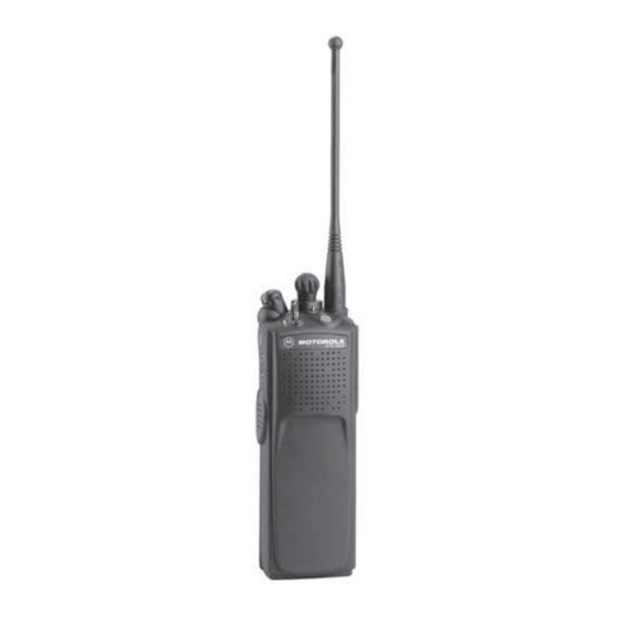
Page 15: Physical Features Of The Xts 5000 Model I Radio
General Radio Operation Physical Features of the XTS 5000 Model I Radio Table 2: Physical Features No. Feature Page No. Feature Page 1 Antenna 5 PTT (Push-to-Talk) Button 2 On/Off/Volume Control 6 Battery Knob 3 LED 7 Speaker 4 Microphone 8 Universal Connector Programmable Controls The following radio controls can be programmed to operate certain... -
Page 16: Backlight
General Radio Operation Table 3: Programmable Features Feature Page Feature Page Feature Page Call Response Nuisance Delete Secure/Clear Channel PL Defeat Site Lock/ Unlock Dynamic Priority Repeater/Direct Site Search Emergency Reprogram TX Power Level Request Light Scan On/Off Volume Set Monitor Scan List Zone... -
Page 17: Alert Tones
General Radio Operation Alert Tones An alert tone is a sound or group of sounds. Your radio uses alert tones to inform you of your radio’s conditions. The following table lists these tones and when they occur. Table 5: Alert Tones You Hear Tone Name Heard... - Page 18 General Radio Operation Table 5: Alert Tones (Continued) You Hear Tone Name Heard Valid Key- when correct key is pressed Press Radio Self-Test when radio passes its power-up Pass self test Clear Voice at beginning of a non-coded Short, communication Medium- Priority when activity on a priority channel...
- Page 19 General Radio Operation Table 5: Alert Tones (Continued) You Hear Tone Name Heard Short, GPS RSM Low when this accessory battery is Medium- Battery Chirp below preset threshold value Pitched Tone (Chirp) Fast Ringing when system is searching for target of Private Call Enhanced Call when waiting for target of Private...
-
Page 20: Standard Accessories
Prior to using a new battery, charge it for a minimum of 16 hours to ensure optimum capacity and performance. For a list of Motorola-authorized batteries available for use with your XTS 5000 radio, see “Batteries and Battery Accessories” on page 49. - Page 21 General Radio Operation Attach the Battery With the radio turned off, insert the top edge of the battery into the radio’s frame as shown. Rotate the battery toward the radio and press down until the battery clicks into place. Remove the Battery With the radio turned off, press the release button on the bottom of the battery until...
-
Page 22: Antenna
General Radio Operation Antenna For information regarding available antennas, see page 46. Attach the Antenna With the radio turned off, turn the antenna clockwise to attach it to the radio. Remove the Antenna With the radio turned off, turn the antenna counterclockwise to remove it from the radio. -
Page 23: Belt Clip
General Radio Operation Belt Clip Attach the Belt Clip Align the grooves of the belt Grooves clip with those of the battery. Slots Battery Battery Press the belt clip downward until you clear a click. Slots Battery Battery Remove the Belt Clip Use a flat-bladed object to press the belt clip tab away Metal... -
Page 24: Universal Connector Cover
General Radio Operation Universal Connector Cover The universal connector is located on the antenna side of the radio. It is used to connect accessories to the radio. Note: To prevent damage to the connector, shield it with the connector cover when not in use. Remove the Connector Cover Insert a flat-bladed screwdriver into the area... -
Page 25: Radio On And Off
General Radio Operation Radio On and Off Turn the Radio On Turn the On/Off/Volume Control knob clockwise. The radio does a self test. Note: If the self test is • Medium-pitched tone successful, you hear a medium-pitched tone. If the self test is not •... -
Page 26: Zones And Channels
General Radio Operation Zones and Channels A zone is a grouping of channels. A channel is a group of radio characteristics, such as transmit/receive frequency pairs. Before you use your radio to receive or send messages, you should select the zone and channel. Select a Zone If a control on your radio has been preprogrammed as the... -
Page 27: Mode Select Button
General Radio Operation Mode Select Button This feature lets you program the current zone and channel to a Mode Select button with a long press on the Mode Select button. After the buttons are programmed, you can return to the pre- programmed zone and channel with a short press on the programmed Mode Select button. -
Page 28: Receive / Transmit
General Radio Operation Receive / Transmit Radio users who switch from analog to digital radios often assume that the lack of static on a digital channel is an indication that the radio is not working properly. This is not the case. Digital technology quiets the transmission by removing the “noise”... -
Page 29: Use The Preprogrammed Monitor Button
General Radio Operation Adjust the Volume Control knob if necessary. Adjust Level Release the Volume Set button. Press and hold the PTT button to transmit. The LED lights RED while transmitting. Release the PTT button to receive (listen). Use the Preprogrammed Monitor Button Turn the radio on and select the desired zone and channel. -
Page 30: Conventional Mode Operation
General Radio Operation Conventional Mode Operation Your radio may be programmed to receive Private-Line® (PL) calls. Momentarily press the Monitor button to listen for activity. Press and hold the Monitor button to set continuous monitor operation. (The duration of the button press is programmable.) Press the Monitor button again, or the PTT button, to... -
Page 31: Common Radio Features
Common Radio Features Selectable Power Level This feature lets you select the power level at which your radio will transmit. This feature must be preprogrammed by a qualified radio technician. • Select Low for a shorter transmitting distance and to conserve power. -
Page 32: Time-Out Timer
Common Radio Features Time-out Timer The time-out timer turns off your radio’s transmitter. The timer is set for 60 seconds at shipment, but it can be programmed from 0 to 7.75 minutes (465 seconds) by a qualified radio technician. Hold down the PTT button •... -
Page 33: Send An Emergency Alarm
Common Radio Features Send an Emergency Alarm An emergency alarm sends a data transmission to the dispatcher, which identifies the radio sending the emergency. With your radio turned on, • Red LED press the Emergency • Short tone button. The red LED lights, and you hear a short, medium-pitched tone. -
Page 34: Send An Emergency Call
Common Radio Features Send an Emergency Call This type of dispatch gives your radio priority access on a channel. The radio operates in the normal dispatch manner while in Emergency Call, except, if enabled, it will return to one of the following: •... -
Page 35: Send A Silent Emergency Alarm
Common Radio Features Send a Silent Emergency Alarm With your radio turned on, • LED does not light press the Emergency • No tones button. The LED does not light, and you hear no tones. Note: To exit emergency at any time, press and hold the Emergency button for about a second. -
Page 36: Lists
Common Radio Features Lists View a Scan List You can view the status of members of one preselected scan list. Select the zone/channel whose scan status you wish to view (see “Zones and Channels” on page 14). Move the preprogrammed Scan List Programming switch to the “scan list programming”... -
Page 37: Edit A Scan List
Common Radio Features Edit a Scan List You can add or change the priority status of members in one preselected scan list. Select the zone/channel you wish to add or whose scan priority status you wish to change (see “Zones and Channels”... - Page 38 Common Radio Features Note: In Scan List Programming mode, the Top Side button automatically becomes the Select button. This is only true while in Scan List Programming mode. The maximum number of members for a conventional scan list is 15. Select additional zones/ channels as desired to add them or to change their scan...
-
Page 39: Scan
Common Radio Features Scan The scan feature allows you to monitor traffic on different channels by scanning a preprogrammed list of channels. Your radio can have up to 32 different scan lists. These lists must be preprogrammed by a qualified radio technician. •... -
Page 40: Conventional Scan Only
Common Radio Features The radio continues scanning the remaining channels in the list. To resume scanning the deleted channel, change channels or turn scan off and then back on again. Conventional Scan Only Make a Dynamic Priority Change While the radio is scanning, the dynamic priority change feature lets you temporarily change any channel in a scan list (except the Priority 1 channel) to the Priority 2 channel. -
Page 41: Individual Calls
Common Radio Features Individual Calls You can answer individual calls made to your radio. Use the preprogrammed Call Response button to answer a call. Answer a Telephone Call (Trunking Only) Use your radio to answer calls similar to standard phone calls. A landline phone can be used to call a radio. -
Page 42: Answer A Selective Call (Astro Conventional Only)
Common Radio Features Press and hold the PTT button to talk; release it to listen. To hang up, press the Call Response button again. Answer a Selective Call (ASTRO Conventional Only) A Selective Call is used to call a select individual. It is intended to provide privacy and to eliminate the annoyance of having to listen to conversations that are of no interest to you. -
Page 43: Select Repeater Or Direct Operation
Common Radio Features Select Repeater or Direct Operation • REPEATER operation = increases radio range by connecting radios through a repeater or repeaters. Transmit and receive frequencies are different. • DIRECT (or Talkaround) operation = You bypass the repeater and connect directly to another radio. -
Page 44: Smart Ptt (Conventional Only)
Common Radio Features Smart PTT (Conventional Only) Smart PTT is a per-channel, programmable feature used in conventional radio systems to keep radio users from talking over other radio conversations. When smart PTT is enabled in your radio, you will not be able to transmit on an active channel. -
Page 45: Special Radio Features
Secure radio operation provides the highest commercially available level of voice security on both trunked and conventional channels. Unlike other forms of security, Motorola digital encryption provides signaling that makes it virtually impossible for others to decode any part of an encrypted message. -
Page 46: Managing Encryption
Special Radio Features Managing Encryption Key Loading Refer to the key-variable loader (KVL) manual for equipment connections and setup. Attach the KVL to your radio. When it is attached, all radio functions, except for power down, backlight, and volume, will be locked out. Press the PTT button on the KVL. - Page 47 Special Radio Features Key Zeroization Note: This is the method used for erasing the single key in radios with the single-key option, and for erasing all keys in radios with the multikey option. With the radio on, press and hold the Top Side button;...
-
Page 48: Dynamic Regrouping (Trunking Only)
Special Radio Features Dynamic Regrouping (Trunking Only) The dynamic regrouping feature lets the dispatcher temporarily reassign selected radios to a single special channel so they can communicate with each other. This feature is typically used during special operations and is enabled by a qualified radio technician. You will not notice whether your radio has this feature enabled until a dynamic regrouping command is sent by the dispatcher. -
Page 49: Reprogram Request (Astro 25 Trunking Only)
Special Radio Features Reprogram Request (ASTRO 25 Trunking Only) This feature lets you notify the dispatcher that you want a new dynamic regrouping assignment. Press the preprogrammed • Reprogram request sent Reprogram Request button. The reprogram request is sent to the dispatcher. If you hear one beep, press the •... -
Page 50: Trunking System Controls
Special Radio Features Trunking System Controls Failsoft The failsoft system ensures continuous radio communications during a trunked system failure. If a trunking system fails completely, the radio goes into failsoft operation and automatically switches to its failsoft channel. During failsoft operation: Your radio transmits and receives in conventional operation on a predetermined frequency. -
Page 51: Site Lock
Special Radio Features Site Lock This feature allows your radio to lock onto a specific site and not roam among wide-area talkgroup sites. This feature should be used with caution, since it inhibits roaming to another site in a wide-area system. -
Page 52: Outdoor Location (Using Gps)
Special Radio Features Outdoor Location (using GPS) The Outdoor Location (using GPS) feature allows radio users using the model with display to determine their current location using a location menu. For non display model, radio location may be reported over-the-air but unknown to users. This feature is only available when a location enabled accessory such as the GPS Remote Speaker Microphone (RSM) is attached to the radio. -
Page 53: Helpful Tips
Motorola details the disassembly, test, and reassembly procedures along with necessary test equipment needed to inspect, maintain and troubleshoot radio seals in the radio’s service manual. -
Page 54: Cleaning
Helpful Tips • If the radio has been submerged in water, shake the radio well so that any water that may be trapped inside the speaker grille and microphone port can be removed. Otherwise, a u t i o n the water will decrease the audio quality of the radio. -
Page 55: Handling
Service Proper repair and maintenance procedures will assure efficient operation and long life for this product. A Motorola maintenance agreement will provide expert service to keep this and all other communication equipment in perfect operating condition. A nationwide service organization is provided by Motorola to support maintenance services. -
Page 56: Battery
25% discharge, will last even longer. Charging the Battery Motorola batteries are designed specifically to be used with a Motorola charger and vice-versa. Charging in non-Motorola equipment may lead to battery damage and void the battery warranty. -
Page 57: Battery Recycling And Disposal
Motorola fully endorses and encourages the recycling of NiCd batteries. In the U.S. and Canada, Motorola participates in the nationwide Rechargeable Battery Recycling Corporation (RBRC) program for NiCd battery collection and recycling. Many retailers and dealers participate in this program. -
Page 58: Antenna
Helpful Tips Antenna Radio Operating Frequencies Before installing the antenna, make sure it matches your radio’s operating frequency. Antennas are frequency sensitive and are color coded according to their frequency range. The color code indicator is located in the center of the antenna’s base. - Page 59 Helpful Tips Approx. Insulator Frequency Antenna Length Antenna Type Color Range Kit No. Code 800 MHz WHITE 806-870 MHz NAF5042 Stubby, Quarterwave 700/800 MHz 178 GREEN 764-870 MHz NAF5080 Whip ASTRO XTS 5000 Model I...
- Page 60 Helpful Tips Notes...
-
Page 61: Accessories
Accessories Motorola provides the following approved accessories to improve the productivity of your XTS 5000 portable two-way radio. Antennas NAD6563 136-174 MHz helical NAD6566 136-150.8 MHz helical NAD6567 150.8-162 MHz helical NAD6568 162-174 MHz helical NAE6546 380-435 MHz helical NAE6547... -
Page 62: Carry Accessories
Accessories NTN8294 1525 mAh NiCd (non-FM/CSA) NTN8295 1525 mAh NiCd Intrinsically Safe (FM/CSA) NTN8297 1525 mAh NiCd Intrinsically Safe (FM/CSA) Ruggedized NTN8299 1700 mAh NiMH Intrinsically Safe (FM/CSA) NTN8610 1650 mAh Li Ion NTN8923 1800 mAh NiMH ultra-capacity (non-FM/CSA) RNN4006 3000 mAh NiMH (non-FM/CSA) RNN4007 3000 mAh NiMH Intrinsically Safe (FM/CSA) -
Page 63: Carry Cases
Accessories NTN8383 T-strap, plain, action snaps NTN9213 Belt loop, 2.5", high-activity, D clip Carry Cases NTN8380 Case, hard leather high-activity (includes swivel belt loop and T-strap), 2.5" belt loop, for Model II and III radios NTN8381 Case, hard leather high-activity (includes swivel belt loop and T-strap), 3.0"... -
Page 64: Surveillance Accessories
Accessories WPLN4130 impres¥ multi-unit, tri-chemistry, with display (US, NA plug) Surveillance Accessories Earpieces BDN6664 Earpiece with standard earphone, beige BDN6665 Earpiece with extra-loud earphone (exceeds OSHA limits), beige BDN6666 Earpiece with volume control, beige BDN6667 Earpiece, mic and PTT combined, beige BDN6668 Earpiece, mic and PTT separate, beige BDN6669... -
Page 65: Headsets And Headset Accessories
Accessories Headsets and Headset Accessories BDN6635 Heavy-duty VOX headset with noise-canceling boom mic (requires BDN6673 adapter cable) BDN6636 Heavy-duty VOX headset with throat mic (requires BDN6673 adapter cable) BDN6645 Noise-canceling boom mic headset with PTT on earcup BDN6673 Headset adapter cable (for use with BDN6635, BDN6636, and BDN6645) BDN6676 3.0 mm threaded adapter jack... -
Page 66: Speaker, Remote Speaker And Public Safety Microphones
Accessories Speaker, Remote Speaker and Public Safety Microphones NMN6191 RSM noise-canceling (includes 6.0' coiled cord assembly, 3.5mm earjack, swivel clip, quick disconnect) NMN6193 Remote speaker mic NMN6247* Public safety mic with straight cord, 30" NMN6250* Public safety mic with straight cord, 24" NMN6251* Public safety mic with straight cord, 18"... -
Page 67: Switches
Accessories Switches 0180300E83 Remote PTT body switch for EMS NTN7660 Tilt / man down switch NTN8327 External RF switch Vehicular Adapters Accessories HMN4069 Next-generation mobile mic HSN1006 Speaker, 6-watt NKN6455 Cable, 6-watt speaker NTN1606 Vehicular adapter, BNC, open face NTN1607 Vehicular adapter, BNC, closed face NTN8560 Vehicular adapter, mini-U, open face... - Page 68 Accessories Notes...
-
Page 69: Glossary
ASTRO 25 Trunking Motorola standard for wireless digital trunked communications. ASTRO Motorola standard for wireless analog or Conventional digital conventional communications. Autoscan A feature that allows the radio to automatically scan the members of a scan list. - Page 70 Glossary Conventional Typically refers to radio-to-radio communications, sometimes through a repeater (see Trunking). Conventional Scan A scan list that includes only conventional List channels. Digital Private Line A type of coded squelch using data bursts. (DPL) Similar to PL except a digital code is used instead of a tone.
- Page 71 Glossary Network Access Network Access Code (NAC) operates on Code digital channels to reduce voice channel interference between adjacent systems and sites. NiCd Nickel-cadmium NiMH Nickel-metal-hydride. Non-tactical/Revert The user will talk on a preprogrammed emergency channel. The emergency alarm is sent out on this same channel. Page A one-way alert, with audio messages.
- Page 72 Glossary Selective Call A feature that allows you to call a select individual, intended to provide privacy and to eliminate the annoyance of having to listen to conversations of no interest to you. Selective Switch Any digital P25 traffic having the correct Network Access Code and the correct talkgroup.
-
Page 73: Commercial Warranty
Product Accessories One (1) Year Motorola, at its option, will at no charge either repair the Product (with new or reconditioned parts), replace it (with a new or reconditioned Product), or refund the purchase price of the Product during the warranty period provided it is returned in accordance with the terms of this warranty. - Page 74 Product item serial number) in order to receive warranty service and, also, deliver or send the Product item, transportation and insurance prepaid, to an authorized warranty service location. Warranty service will be provided by Motorola through one of its authorized warranty service locations. If you first contact the company...
- Page 75 Commercial Warranty which sold you the Product, it can facilitate your obtaining warranty service. You can also call Motorola at 1-888-567-7347 US/Canada. V. WHAT THIS WARRANTY DOES NOT COVER: A) Defects or damage resulting from use of the Product in other than its normal and customary manner.
- Page 76 A) that MOTOROLA will be notified promptly in writing by such purchaser of any notice of such claim; B) that MOTOROLA will have sole control of the defense of such suit and all negotiations for its settlement or compromise; and C) should the Product or parts become, or in MOTOROLA’s...
- Page 77 Commercial Warranty the use of ancillary equipment or software not furnished by MOTOROLA which is attached to or used in connection with the Product. The foregoing states the entire liability of MOTOROLA with respect to infringement of patents by the Product or any parts thereof.
- Page 78 Commercial Warranty Notes...
-
Page 79: Appendix: Maritime Radio Use In The Vhf Frequency Range
Appendix: Maritime Radio Use in the VHF Frequency Range Special Channel Assignments Emergency Channel If you are in imminent and grave danger at sea and require emergency assistance, use VHF Channel 16 to send a distress call to nearby vessels and the United States Coast Guard. Transmit the following information, in this order: “MAYDAY, MAYDAY, MAYDAY.”... -
Page 80: Non-Commercial Call Channel
Appendix: Maritime Radio Use in the VHF Frequency Range Non-Commercial Call Channel For non-commercial transmissions, such as fishing reports, rendezvous arrangements, repair scheduling, or berthing information, use VHF Channel 9. Operating Frequency Requirements A radio designated for shipboard use must comply with Federal Communications Commission Rule Part 80 as follows: •... - Page 81 Appendix: Maritime Radio Use in the VHF Frequency Table A-1: VHF Marine Channel List (Continued) Frequency (MHz) Channel Number Transmit Receive 156.400 – 156.450 156.450 156.500 156.500 156.550 156.550 156.600 156.600 13** 156.650 156.650 156.700 156.700 15** 156.750 156.750 156.800 156.800 17** 156.850...
- Page 82 Appendix: Maritime Radio Use in the VHF Frequency Range Table A-1: VHF Marine Channel List (Continued) Frequency (MHz) Channel Number Transmit Receive 67** 156.375 156.375 156.425 156.425 156.475 156.475 156.575 156.575 156.625 – 156.675 156.675 156.725 156.725 77** 156.875 – 156.925 161.525 156.975...
-
Page 83: Index
Index keep alive ........ 23 send a silent emergency alarm 23 accessories .........49 send an emergency alarm ..21 alert tones ........5 send an emergency call ..22 antenna ........10 encryption attach ........10 key loading ......34 radio operating frequencies ..46 key zeroization ...... - Page 84 Index site change the current site .... 39 PL defeat ........19 lock .......... 39 programmable controls ....3 smart PTT (conventional only) ..32 special radio features ....33 standard accessories ....8 radio surveillance accessories ..... 52 care CommPort integrated microphone/ cleaning .......42 receivers ........
- Page 86 MOTOROLA, the Stylized M Logo and ASTRO are registered in the U.S. Patent & Trademark Office. All other product or service names are the property of their respective owners. © 2001, 2002, 2003, 2005, 2008 and 2009 by Motorola, Inc. All rights reserved. *6881094C25*...
Need help?
Do you have a question about the Astro XTSTM 5000 and is the answer not in the manual?
Questions and answers