Table of Contents
Advertisement
Quick Links
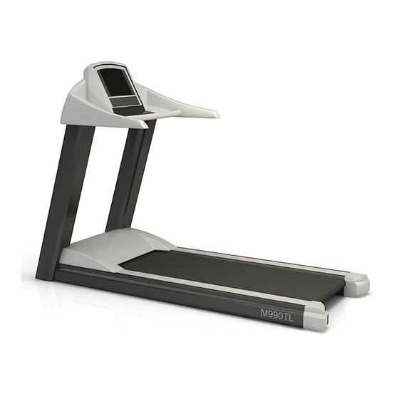
M990T, M990TL, M995T, M995TL
Treadmill
SERVICE MANUAL
This service manual is for use by Motus trained service providers only.
If you are not a Motus Trained Servicer, you must not attempt to service any Motus product.
Ver 0.2, Feb., 2007
Motus Co., Ltd. All Rights reserved.
Unauthorized Reproduction and Distribution Prohibited By Law
Advertisement
Table of Contents
Troubleshooting

Subscribe to Our Youtube Channel
Related Manuals for Motus M990T


Summary of Contents for Motus M990T
-
Page 1: Service Manual
SERVICE MANUAL This service manual is for use by Motus trained service providers only. If you are not a Motus Trained Servicer, you must not attempt to service any Motus product. Ver 0.2, Feb., 2007 Motus Co., Ltd. All Rights reserved. - Page 2 Motus Treadmills M990T, M990TL, M995T and M995TL Table of Contents SECTION I TROUBLESHOOTING GUIDE SECTION II HOW TO REPLACE & REPAIR GUIDE General SECTION III HOW TO REPLACE & REPAIR GUIDE, Electronic PCB SECTION IV ELECTRONIC PCB, CONNECTOR AND CABLE OVERVIEW...
-
Page 3: Troubleshooting Guide
Motus Treadmills M990T, M990TL, M995T and M995TL SECTION I TROUBLESHOOTING GUIDE 1.1 System Block Diagram 1.2 Troubleshooting Guide 1.3 Troubleshooting Guide for LCD 1.4 Protective Function & Display Code 1.5 Lubrication Guide... - Page 4 1.1 System Block Diagram 1) AC 220V/230V INPUT Touch -Sensitive Lift/ Lift Motor Key PCB (L/R) Power Supply Speed/Incline/ Start/Enter Emergency Oil Pump Motor Switch MPU PCB Transformer (Main CHR PCB Processing Wireless HR Unit) Circuit Membrane Overlay Key 220V/230V Breaker Motor Line...
- Page 5 2) AC 100V/120V INPUT (USA, Japan) Touch -Sensitive Lift Lift Motor Key PCB (L/R) /Power Supply Speed/Incline/ Start/Enter Emergency Oil Pump Motor Switch MPU PCB Transformer AC 230V/240V (Main CHR PCB Processing Boost Wireless HR Unit) Transformer Circuit Membrane Overlay Key 100V/120V Breaker AC 100V/120V...
- Page 6 1.2 Troubleshooting Guide SYMPTOM PROBABLE CAUSE CORRECTIVE ACTION Check the main circuit breaker and wall outlet voltage at Line voltage is not present at treadmill. the Facility. If wall outlet voltage is present, then replace line cord. If tripped, a white button has popped out. Press the white Circuit breaker on the rear of the Treadmill Is tripped.
- Page 7 CORRECTIVE ACTION Disconnect CN6 (3-pin connector) on MPU PCB (M990T/M995T) and then measure the voltage between pin 2 and pin 1 at the cable. Measure the voltage between pin 2 and pin 3 at the cable. If there is no voltage, replace the cable.
- Page 8 Unstable cable connection. Check the connection between CN3 on Lift/Power Supply PCB and CN6 (M990T/M995T) on MPU PCB is connected firmly. Replace belt and deck. The deck laminate worn through or the underside of striding belt (Refer to section “How to replace Striding Belt”, “How to...
- Page 9 SYMPTOM PROBABLE CAUSE CORRECTIVE ACTION If all 3 lamps on Start/Stop, Speed Down and Speed UP do not light up, replace the Touch-Sensitive Key PCB. Touch-Sensitive Buttons does not work. If a lamp on Start/Stop, Speed Down or Speed UP does not light up any more than before pressing each button, replace the Touch-Sensitive Key PCB.
- Page 10 SYMPTOM PROBABLE CAUSE CORRECTIVE ACTION Treadmill changes Touch-Sensitive Key PCB is affected by some noise. Replace the Touch-Sensitive Key PCB. Speed or Incline on Sweat or water over the buttons. Remove sweat or water. its own. Treadmill shuts Touch-Sensitive Key PCB is affected by some noise. Replace the Touch-Sensitive Key PCB.
- Page 11 SYMPTOM PROBABLE CAUSE CORRECTIVE ACTION Heart rate reading is Electromagnetic interference from television sets, cell phones, Keep the treadmill away from the probable cause until abnormally high or is refrigerator, or motor driven exercise equipment. the heart rate readings are accurate. displayed even when Chest Strap or Keep another chest strap away more than 1 meter until...
- Page 12 1.3 Troubleshooting Guide for LCD Symptom/Condition PROBABLE CAUSE CORRECTIVE ACTION Air/cable setting Follow the set up procedures in LCD manual. correct - Check if the TV signal source is correctly supplied to A/D PCB from external source. Snow and noise are scattering on LCD screen. Any picture is - Make sure the cable is properly secure.
- Page 13 tighten midpoint (LCD Power Supply side) & endpoint(A/D Board side) connection. or make sure the voltage of end point is DC 12 volt. The cable related to LCD Lamp Inverter is loose in Check if the connection is secure. either side. TV on/off button is wrong or Replace OSD Button Board.
- Page 14 1.4 Protective Function & Display Code If a treadmill stops suddenly, it means a protective function works properly. This is normal function to protect the treadmill. As the result of protective function, a code indicating the cause of error is displayed on the display console or the display panel of Motor Controller (or Motor Inverter) which is located under motor hood.
- Page 15 - Regenerative energy from motor is too much. compulsorily by foot. - Replace Motor Controller cable with - External noise Communication new one - Trouble in internal memory due to or high temperature. Error - Replace Motor Controller with new - Cable connection between MPU and Motor Controller Unexpected low voltage is detected at DC voltage of Motor - Check the input voltage to treadmill.
- Page 16 2) Open the cap of oil tank by turning it with hand. 3) Fill the empty tank fully with the oil provided by Motus. Keep in mind that automatic lubrication system doesn’t work properly if oil is not filled full.
- Page 17 To judge proper lubrication timing, you can feel the friction intensity by pushing the striding belt backward using your feet while holding the front handle after turn OFF the treadmill. 1. Fill the lubricator with the oil Motus provided. 2. The conduction hole for the lubrication is at the right corner on the front of the treadmill as shown in the picture.
- Page 18 Numeric value 5 in management mode means interval of 500 km. If you exercise on treadmill at 8km/h for 10 hours a day, total distance a day is 80km and the warning beep and symbol appears every 6.25 days corresponding to 500 divided by 80. The speed (8km/h) and workout duration for a day (10 hours) depend on the numbers of the users or utilization rate ay Gym.
-
Page 19: Table Of Contents
Motus Treadmills M990T, M990TL, M995T and M995TL SECTION II HOW TO REPLACE & REPAIR GUIDE General 2.1 How to Stabilize the Treadmill 2.2 How to Align Striding Belt 2.3 How to Adjust Striding Belt Tension 2.4 How to Adjust Motor Drive Belt Tension 2.5 How to Replace the Rear Roller... -
Page 20: How To Stabilize The Treadmill
2.1 How to Stabilize the Treadmill Two front casters and two adjustable rear feet (or stabilizing leg) support the weight of both the treadmill and a user exercising on it. The rocking motion or striding belt misalignment may be caused when one of them is not resting on the floor. 1) Check if the treadmill is even on a solid and flat surface. -
Page 21: How To Align Striding Belt
2.2 How to Align Striding Belt The belt is properly aligned at the factory before shipment. However, while delivering or exercising, the belt can be misaligned from the original center position. The correct alignment or striding belt is critical to the smooth operation of the treadmill. 2.2.1 When the belt is off center to either right direction or left direction 1) Level and stabilize the treadmill prior to any alignments or tracking adjustments. - Page 22 getting damaged, stop the treadmill and contact authorized local dealer. 2.2.2 When the belt is diagonally tilted When the Striding Belt is diagonally tilted as shown, the Front Roller (F4) needs to be aligned by following steps. 1) Turn off the unit power at the switch and then unplug the line cord at wall outlet.
-
Page 23: How To Adjust Striding Belt Tension
2.3 How to Adjust Striding Belt Tension Belt tension is properly adjusted before delivery. However, while exercising for a long time, the tension can be loose. Belt tension is adjusted by moving the position of rear roller using the belt tensioning bolt of END CAP. -
Page 24: How To Adjust Motor Drive Belt Tension
The Drive Motor Pulley and Motor Drive Belt. The tension is corrected by adjusting the mounting position of the Drive Motor (M1). Do the steps below while referring to the following Exploded Views in Appendix. A.1 M990T B.1 MAIN BODY_FRONT A C.1 MAIN BODY_REAR 1) Stop the treadmill after lifting up the unit at maximum by operating Incline Motor. - Page 25 because tightening two nuts (N2) increases the tension of the Motor Drive Belt. 8) Measure the Tension again. If the tension is lower than 155Hz or higher than 165Hz, re- adjust the tension 4 through 8) until it reaches 155Hz to 165Hz. 9) When the tension reaches 160 Hz, tighten the nut (N3) securing the Tension Bolt (B7).
-
Page 26: How To Replace The Rear Roller
2.5 How to Replace the Rear Roller Do the steps below while referring to the following Exploded Views in Appendix. A.1 M990T B.1 MAIN BODY_FRONT A C.1 MAIN BODY_REAR 1) Turn off the unit power at the switch and then unplug the line cord at wall outlet. - Page 27 2.6 How to Replace the Front Roller Do the steps below while referring to the following Exploded Views in Appendix. A.1 M990T B.1 MAIN BODY_FRONT A C.1 MAIN BODY_REAR 1) Stop the treadmill after lifting up the unit at maximum by operating Incline Motor.
- Page 28 Belt (POLY-V BELT). 12) Remove two bolts (B16, B2) securing the FRONT ROLLER (F4) and then remove the FRONT ROLLER out from the left side of the frame, through the underside the Striding Belt. Remove the DRIVE BELT (M3) out and save for a new Front Roller. 13) Install the new Front Roller and the Drive Motor Belt into position and secure in place with the mounting bolt (B16, B2).
-
Page 29: How To Replace The Striding Belt
2.7 How to Replace the Striding Belt Do the steps below while referring to the following Exploded Views in Appendix. A.1 M990T B.1 MAIN BODY_FRONT A C.1 MAIN BODY_REAR 1) Stop the treadmill after lifting up the unit at maximum by operating Incline Motor. - Page 30 FRONT ROLLER out from the left side of the frame, through the underside the Striding Belt. Remove the DRIVE BELT (M3) out and save for a new Front Roller. 13) Remove the eight mounting bolts (B13) and then remove the DECK (F2). 14) Position a new Striding Belt (F3) onto the center of the frame inside unit and then install the saved DECK (F2) by tightening the eight mounting bolts (B13).
-
Page 31: How To Replace The Motor Drive Belt
2.8 How to Replace the Motor Drive Belt Do the steps below while referring to the following Exploded Views in Appendix. A.1 M990T B.1 MAIN BODY_FRONT A C.1 MAIN BODY_REAR 1) Stop the treadmill after lifting up the unit at maximum by operating Incline Motor. -
Page 32: How To Replace The Deck
2.9 How to Replace the DECK Do the steps below while referring to the following Exploded Views in Appendix. A.1 M990T B.1 MAIN BODY_FRONT A C.1 MAIN BODY_REAR 1) Turn off the unit power at the switch and then unplug the line cord at wall outlet. - Page 33 2.10 How to Replace Drive Motor Do the steps below while referring to the following Exploded Views in Appendix. A.1 M990T B.1 MAIN BODY_FRONT A C.1 MAIN BODY_REAR 1) Stop the treadmill after lifting up the unit at maximum by operating Incline Motor.
- Page 34 cables to the Motor Controller as shown. U, V or W is marked on three Cables. 9) Remove four bolts (B9), washers (W2) and four nuts (N2) and then lift the Drive Motor (M1) out. 10) Install a new Drive Motor in the reverse order of removal and then connect the three Cables from the Drive Motor to the Motor Controller.
- Page 35 2.11 How to Replace the Incline Motor Do the steps below while referring to the following Exploded Views in Appendix. A.1 M990T B.1 MAIN BODY_FRONT A 1) Turn off the unit power at the switch and then unplug the line cord at wall outlet.
- Page 36 10) Reassemble remaining components in the reverse order of removal. 11) Turn on the treadmill and then make sure that the Incline function is working properly.
-
Page 37: How To Replace The Oil Pump
2.12 How to Replace the Oil Pump Do the steps below while referring to the following Exploded Views in Appendix. A.1 M990T B.1 MAIN BODY_FRONT A 1) Stop the treadmill after lifting up the unit at maximum by operating Incline Motor. - Page 38 2.13 How to Replace the Contact Heart Rate Sensor Do the steps below while referring to the following Exploded Views in Appendix. E.1 CONSOLE ASSEMBLY 1) Turn off the unit power at the switch and then unplug the line cord at wall outlet. 2) Remove four screws (B25) and two screws (B21) securing SIDE HANDLE TOP/BOTTOM (C6, C7, C8 &...
-
Page 39: How To Replace & Repair Guide
3.1 How to Replace the LCD Screen 3.2 How to Replace the MPU Board in Model M990TL and M995TL 3.3 How to Replace the MPU Board in Model M990T and M995T 3.4 How to Replace the Touch Sensitive Key Board 3.5 How to Replace the Lift/Power Board... - Page 40 3.1 How to Replace the LCD Screen Do the steps below while referring to the following Exploded Views in Appendix and Section ELECTRONIC PCB, CONNECTOR AND CABLE OVERVIEW. D.1 OVERLAY BEZEL ASSEMBLY E.1 CONSOLE ASSEMBLY 1) Turn off the unit power at the switch and then unplug the line cord at wall outlet. 2) Remove eleven screws (B23) from the Console Bottom (C2).
- Page 41 11) Disconnect the OSD Button Cable from either OSD Button PCB (L7) or A/D Board (L13). 12) Reverse LCD Metal Bracket (L12) so that the LCD Screen (L11) faces upward. 13) Remove four bolts (B34) securing the LCD Screen to LCD Metal Bracket and then lift the LCD Screen off.
- Page 42 3.2 How to Replace the MPU Board in Model M990TL and M995TL Do the steps below while referring to the following Exploded Views in Appendix and Section ELECTRONIC PCB, CONNECTOR AND CABLE OVERVIEW. D.1 OVERLAY BEZEL ASSEMBLY E.1 CONSOLE ASSEMBLY 1) Turn off the unit power at the switch and then unplug the line cord at wall outlet.
- Page 43 3.3 How to Replace the MPU Board in Model M990T and M995T Do the steps below while referring to the following Exploded Views in Appendix and Section ELECTRONIC PCB, CONNECTOR AND CABLE OVERVIEW. D.1 OVERLAY BEZEL ASSEMBLY E.1 CONSOLE ASSEMBLY 1) Turn off the unit power at the switch and then unplug the line cord at wall outlet.
- Page 44 3.4 How to Replace the Touch Sensitive Key Board Do the steps below while referring to the following Exploded Views in Appendix and Section ELECTRONIC PCB, CONNECTOR AND CABLE OVERVIEW. E.1 CONSOLE ASSEMBLY 1) Turn off the unit power at the switch and then unplug the line cord at wall outlet. 2) Remove eleven screws (B23) from the Console Bottom (C2).
- Page 45 Do the steps below while referring to the following Exploded Views in Appendix and Section ELECTRONIC PCB, CONNECTOR AND CABLE OVERVIEW. A.1 M990T B.1 MAIN BODY_FRONT A 1) Turn off the unit power at the switch and then unplug the line cord at wall outlet.
- Page 46 3.6 How to Replace the A/D Board Do the steps below while referring to the following Exploded Views in Appendix and Section ELECTRONIC PCB, CONNECTOR AND CABLE OVERVIEW. D.1 OVERLAY BEZEL ASSEMBLY E.1 CONSOLE ASSEMBLY 1) Turn off the unit power at the switch and then unplug the line cord at wall outlet. 2) Remove eleven screws (B23) from the Console Bottom (C2).
- Page 47 3.7 How to Replace the Lamp Inverter Board Do the steps below while referring to the following Exploded Views in Appendix and Section ELECTRONIC PCB, CONNECTOR AND CABLE OVERVIEW. D.1 OVERLAY BEZEL ASSEMBLY E.1 CONSOLE ASSEMBLY 1) Turn off the unit power at the switch and then unplug the line cord at wall outlet. 2) Remove eleven screws (B23) from the Console Bottom (C2).
- Page 48 3.8 How to Replace the Program Button, OSD Button & Audio Interface Board in Model M990TL and M995TL Do the steps below while referring to the following Exploded Views in Appendix and Section ELECTRONIC PCB, CONNECTOR AND CABLE OVERVIEW. D.1 OVERLAY BEZEL ASSEMBLY (LCD TYPE) E.1 CONSOLE ASSEMBLY 1) Turn off the unit power at the switch and then unplug the line cord at wall outlet.
- Page 49 9) Remove three screws (B33) securing Program Button Board (L6) and lift off the Program Button Board (L6) from the LCD Overlay Bezel (L5). 10) Install new Program Button Board in reverse order. OSD Button Board 8) Disconnect the OSD Button Cable (CB15) from the OSD Button Board (L7). 9) Remove three screws (B33) securing the OSD Button Board (L7) and lift off the OSD Button Board (L6) from the LCD Overlay Bezel (L5).
- Page 50 3.9 How to Replace the Logo-Lighting & Key Conversion Board in Model M990T and M995T Do the steps below while referring to the following Exploded Views in Appendix and Section ELECTRONIC PCB, CONNECTOR AND CABLE OVERVIEW. D.1 OVERLAY BEZEL ASSEMBLY (DOT TYPE) E.1 CONSOLE ASSEMBLY...
- Page 51 3.10 How to Replace the CHR (Contact Heart Rate) Board or Combo Board 3.10.1 Old Version CHR Board Note: Old version CHR Board is mounted on MPU Board as Piggy Back Board. Do the steps below while referring to the following Exploded Views in Appendix and Section ELECTRONIC PCB, CONNECTOR AND CABLE OVERVIEW.
- Page 52 3.10.2 Replacing Old Version CHR Board with New Version CHR Board Note: Replacing Old version CHR Board with New Version CHR Board. Old version CHR Board is located on MPU Board as Piggy Back Board. Do the steps below while referring to the following Exploded Views in Appendix and Section ELECTRONIC PCB, CONNECTOR AND CABLE OVERVIEW.
- Page 53 12) Connect 3-pin cable between the CHR Board and MPU PCB (CN7 on L9 Board or CN10 on D4 Board). 13) Connect two 2-pin cables coming from Contact Sensor to the CHR Board. 14) Re-install all of disassembled parts in reverse order.
- Page 54 3.10.3 New Version CHR Board Do the steps below while referring to the following Exploded Views in Appendix and Section ELECTRONIC PCB, CONNECTOR AND CABLE OVERVIEW. D.1 OVERLAY BEZEL ASSEMBLY E.1 CONSOLE ASSEMBLY 1) Turn off the unit power at the switch and then unplug the line cord at wall outlet. 2) Remove eleven screws (B23) from the Console Bottom (C2).
- Page 55 Motus Treadmills M990T, M990TL, M995T and M995TL SECTION IV ELECTRONIC PCB, CONNECTOR AND CABLE OVERVIEW 4.1 Cable Connection Block Diagram 4.2 Electronic PCB, Connector and Pin Description 4.3 Cables & Connectors 4.4 Cable Diagram...
- Page 56 4.1 Cable Connection Block Diagram 1) MPU PCB (LCD Type)
- Page 57 2) MPU PCB (DOT Type)
- Page 58 3) A/D BOARD...
- Page 59 4) Lift/Power BOARD 4-1) Supply Voltage: 220/230VAC...
- Page 60 4-2) Supply Voltage: 100/120VAC (USA, Japan)
- Page 61 4.2 Electronic PCB, Connector and Pin Description 1) MPU (LCD Type), M990TL/M995TL Connector Location Pin Name Functional Description CN 1: Main Power VCC3A 5V for DOT Display It Is connected to Ground Lift/Power PCB VCC_MPU 5V for System Power CN 2 : GND_HR Ground for HR Lift/Power Control...
- Page 62 Connector Location Pin Name Functional Description CN 3 : TV Power Control CN 5 : Serial Port (RS-232) TXD_PC Transmit data ( M990T (Reserved) RXD_PC Receive data( PC M990T ) Ground CN 6 : T232/PDO Program Data Output Program Download...
- Page 63 Connector Location Pin Name Functional Description CN 13 : Data Input 4 Ribbon Connector Data Input 3 for Membrane Overlay Data Input 2 Data Input 1 Data Output 6 Data Output 5 Data Output 4 Data Output 3 Data Output 2 Data Output 1 CN 14 : V_TCH...
- Page 64 Connector Location Pin Name Functional Description CN 17 : Push Button Emergency Switch Ground RJ 1 : Communication for Motor Controller N/C. Signal + N/C. Signal - VDD_485 GND_485 Ground...
- Page 65 2) MPU (DOT TYPE) M990T/M995T Connector Location Pin Name Functional Description CN 1 : T232/PDO Program Data Output Program Download Serial Clock R232/PDI Program Data Input RESET Reset Ground CN 2 : System +5V Key Conversion for Key 1 Key Invert signal...
- Page 66 Oil_PMP Oil Pump On/Off SEN_PMP Oil Pump sencing N/C. CN 5 : Serial Port (RS-232) TXD_PC Transmit data ( M990T RXD_PC Receive data( PC M990T ) Ground CN 6 : Main Power VCC3A 5V for DOT Display which is connected to...
- Page 67 Connector Location Pin Name Functional Description CN 12 : Touch Signal 1 Touch Plate signal 2-1 Heart Rate Sensor Signal 2 Touch Plate signal 2-2 CN 13 : Data Input 4 Ribbon Cable for Data Input 3 Membrane Overlay Data Input 2 Data Input 1 Data Output 6 Data Output 5...
- Page 68 Connector Location Pin Name Functional Description CN 17 : System Ground Logo Backlight VCC3A System +5V VCC3A System +5V System Ground RJ 1 : Communication for Motor Controller Signal + Signal - VDD_485 GND_485 Ground...
- Page 69 3) Touch Sensitive Key Board Connector Location Pin Name Functional Description CN 1 : V_TCH Touch VCC Right Touch Sensitive GND_TCH Touch Ground Key. START/STOP Start/Stop Key (Start/Stop, Speed Up & SPEED- Speed Down Key Speed Down) SPEED+ Speed Up Key LIGHT_CON VCC3A System +5V...
- Page 70 4) Lift/Power Board Connector Location Pin Name Functional Description CN 1 : AC Power Transformer Output AC Power AC Power AC Power CN 2 : AC Power Transformer Output AC Power AC Power AC Power AC Power AC Power AC Power AC Power CN 3 : VCC3A...
- Page 71 Connector Location Pin Name Functional Description CN 4 : GND_HR Ground for HR Lift/Power Board V_HR Vcc for HR Control ENC/P Encoder Pulse Over Load EMERG Emergency INCL_ON Incline Relay On INCL_CON Incline Control GND_TCH Touch Ground V_TCH Touch Vcc System Ground VCC_12V 12V for Buzzer...
- Page 72 Connector Location Pin Name Functional Description CN 9 : Reserved CN 10 : Reserved CN 11 : Oile Pump Control CN 20 : Incline Common Lift Motor Control Incline Up DOWN Incline Down AC 1 : AC Power 220VAC Power Input AC 2 : AC Power 220VAC Power Input...
- Page 73 5) A/D Board Connector Location Pin Name Functional Description CN 1 : Audio Out Audio Left Audio Left Ground Audio Right Audio Right Ground CN 2 : S-VIDEO SVIDEO Input CN 3 : DC In DC 12V/3.5A Input CN 5 : Video In (RCA) Video Input (Yellow) CN 8 : Audio In (RCA) Audio Input (Red)
- Page 74 Connector Location Pin Name Functional Description CN 11 : LED1 LDE Lamp OSD Button KEY1 Key Input KEY2 Key Input Vcc DC 5V Ground LED2 LED Lamp IR Sensor CN 12 : S-AUDIO In S-AUDIO In S-AUDIO Input CN 14 : RGB In TU 1 : RF ANT In RF ANT In Coaxial TV...
- Page 75 LVDS Control O 3- LVDS ODD O CLK + LVDS ODD O CLK - LVDS ODD Ground O 2+ LVDS ODD O 2- LVDS ODD O 1+ LVDS ODD O 1- LVDS ODD O 0+ LVDS ODD O 0- LVDS ODD...
- Page 76 6) LAMP Inverter Board Connector Location Pin Name Functional Description CN 1 : Lamp Inverter Control Lamp Inverter Control Lamp Inverter Control Lamp Inverter Control Lamp Inverter Control Lamp Inverter Control Lamp Inverter Control Lamp Inverter Control Lamp Inverter Control Lamp Inverter Control Lamp Inverter Control Lamp Inverter Control...
- Page 77 7) OSD Button Board Connector Location Pin Name Functional Description CN 3 : No Connection KEY1 Key 1 Output (Volume up, Channel down & Channel up) KEY2 Key 2 Output (Volume down, Power) Vcc 5V Ground 8) Program Button Board Connector Location Pin Name...
- Page 78 9) Key Conversion Board Connector Location Pin Name Functional Description CN 2 : Vcc 5V 10KEY_LED Key LED RED 10KEY_LED\ Key LED GREEN 10) Logo Backlight Board Connector Location Pin Name Functional Description CN 1 : Ground Vcc 5V Vcc 5V Ground...
- Page 79 11) Audio Interface Board Connector Location Pin Name Functional Description CN 6 : Audio-L Sound Left Audio-R Sound Right Ground 12) Wireless Heart Rate Board 13) Contact Heart Rate Board...
- Page 80 4.3 Cables & Connectors Cable Connector Connector Length Start Board End Board Wire Housing Remark [mm] Lift/Power 2,000 SMH250-15 Lift/Power 2,000 LH1143-03 Touch-Sensitive SMH250-08 CB3R CN15 Right Touch-Sensitive SMH250-08 CB3L CN16 Left CB4R CN12 HR Sensor-R 1,200 SMH250-02 Main PCB CB4L HR Sensor-L 1,200...
- Page 81 Cable Start Point Connector End Point Connector Length Wire Housing Remark or Board or Board [mm] CB19 Yellow Terminal AD Board CB19 Board CB19 White AC Inlet-1 Switch-11 AC Inlet-2 Switch-12 AC Inlet-3 Earth Circuit Switch-21 Protector-1 Circuit Noise Filter-11 Protector-2 Switch-22 Noise Filter-12...
-
Page 82: Cable Diagram
4.4 Cable Diagram Cable No. Cable Name Cable Spec Remark Main Power Cable Lift/Power Control Cable Touch Sensitive CB3R,CB3L Key Cable Program Button CB12 Cable Logo-Backlight Cable Key Conversion Cable Communication CB11 Cable (RJ-45) J7, J8 AC1, AC2 CB4L, CB4R Contact HR Cable LCD Power Supply Cable... - Page 83 Cable No. Cable Name Cable Spec Remark Earth Cable J1, J2, J4, J5, J6 Audio Interface Cable CB15 OSD Button Cable CB16 LVDS Cable CB17 Lamp Inverter Cable Coaxial Cable CB18 Old type (NTSC) Coaxial Cable CB18 Old type (PAL/SECAM) Coaxial Cable CB18 New type...
- Page 84 Cable No. Cable Name Cable Spec Remark CB20 S-VIDEO Cable CB21 S-AUDIO Cable LCD Power Supply CB22 Cable...
-
Page 85: Exploded View
Motus Treadmills M990T, M990TL, M995T and M995TL APPENDIX EXPLODED VIEW A. M990T – PART LIST A.1. M990T – EXPLODED VIEW B. MAIN BODY_FRONT – PART LIST B.1 MAIN BODY_FRONT A – EXPLODED VIEW B.2 MAIN BODY_FRONT B – EXPLODED VIEW C. - Page 86 A. M990T CODE P/NAME SPEC Q’TY MAP151010 CONSOEL CASE (CONSOLE ASSEMBLY) MAP184100 HANDLE FRAME_L MAP184110 HANDLE FRAME_R MAP184010 SIDE HANDLE_TOP_L MAP184030 SIDE HANDLE_BOTTOM_L MAP184020 SIDE HANDLE_TOP_R MAP184040 SIDE HANDLE_BOTTOM_R MAP191010 MOTOR COVER MAC191020 BADGE-COVER MAP181000 SUPPORT_L MAP182000 SUPPORT_R MAP197010 STICKER_SIDE...
- Page 87 A.1 M990T...
- Page 88 B. MAIN BODY_FRONT CODE P/NAME SPEC Q’TY MAK131010 MOTOR MAOD31090 MOTOR BASE PLATE BAKELITE MAP141041 POLY-V BELT MAP131090 MOTOR ARRANGEMENT BRACKET MAK171010 INVERTER N100 MAP171030 TRANSFORMER U.S.A. SPEC MAP122010 LIFT MOTOR MAO499200 LINE FILTER RF215-TS MAC199200 LINE FILTER for WIRELESS H/R RF415 MAOD99201 LINE FILTER...
- Page 89 CODE P/NAME SPEC Q’TY MAP131060 DRIVE MOTOR PULLEY MAO111040 TERMINAL STICKER_LCD MAPD93000 POWER SWITCH WITH CIRCUIT BREAKER MAOD94001 POWER CODE MAOD90500 POWER CODE HOLDER MAP111010 TERMINAL PLATE_DOT MAOD11010 TERMINAL PLATE_LCD MAPD11010 TERMINAL PLATE_DOT MAP111040 TERMINAL STICKER_DOT MAOD11040 TERMINAL STICKER_LCD MAPD11040 TERMINAL STICKER_DOT BRACKET...
- Page 90 B.1 MAIN BODY_FRONT A...
- Page 91 B.2 MAIN BODY_FRONT B...
- Page 92 C. MAIN BODY_REAR CODE P/NAME SPEC Q’TY MAP111000 MAIN FRAME MAP142010 DECK MAP142000 RUNNING BELT MAP141011 FRONT ROLLER MAP141021 REAR ROLLER MAP144030 NONSLIP SIDE_L MAP144040 NONSLIP SIDE_R MAP144010 NONSLIP TOP MAP144050 NONSLIP PVC MAP145010 END CAP_L MAP145020 END CAP_R MAP112000 STABILIZER MAP113000 STABILIZER RUBBER...
- Page 93 C.1 MAIN BODY_REAR...
- Page 94 D. OVERLAY BEZEL ASSEMBLY CODE P/NAME SPEC Q’TY MAO151060 ACRYLIC PANEL LCD MAO151140 BUTTON LCD_L MAO151140 BUTTON LCD_R MAO451020 LCD MEMBRANE OVERLAY ENGLISH MAO151050 LCD OVERLAY BEZEL MAO167221 PROGRAM BUTTON BOARD MAO167121 OSD BUTTON BOARD MAP161010 AUDIO INTERFACE BOARD MAO162011 MPU BOARD MAP151290 PANEL BRACKET...
- Page 95 D.1 OVERLAY BEZEL ASSEMBLY...
- Page 96 E. CONSOLE ASSEMBLY CODE P/NAME SPEC Q’TY MAP151010 CONSOLE CASE MAP152010 CONSOLE BOTTOM MAP184090 HANDLE FRAME MAP184100 HANDLE FRAME_L MAP184110 HANDLE FRAME_R MAP184010 SIDE HANDLE_TOP_L MAP184030 SIDE HANDEL_BOTTOM_L MAP184020 SIDE HANDLE_TOP_R MAP184040 SIDE HANDLE_BOTTOM_R MAP185000 HANDLE CROSS PIPE MAP185010 FRONT HANDLE_TOP MAP185020 FRONT HANDLE_BOTTOM MAJ182030...
- Page 97 ENGLISH MAP151160 CONSOLE STICKER_L KOREAN MAP451170 CONSOLE STICKER_R ENGLISH MAP151170 CONSOLE STICKER_R KOREAN MAP151040 SWITCH STICKER MAP151320 STICKER CONSOLE BACK MOTUS MAPD11040 SYMBOL MAGNET MAP111010 EMERGENCY MAGNET SWITCH MAOD11010 EMERGENCY STICKER MAPD11010 EMERGENCY PLATE MAP151250 CASE HOLDER MAP152020 DOWNROAD CABLE...
- Page 98 E.1 CONSOLE ASSEMBLY...
- Page 99 F. BOLT, WASHER & NUT CODE P/NAME SPEC Q’TY MA0A12100 ALLEN BOLT M12*L100 MA0K12065 HEX BOLT M12*L65 MA0C12060 ALLEN BUTTON BOLT M12*L60 MA0K12030 HEX BOLT M12*L30 MA0K12025 HEX BOLT M12*L25 MA0I10120 H/S ALLEN BOLT M10*L120, TAP35 MA0K10045 HEX BOLT M10*L45 MA0I10050 H/S ALLEN BOLT M10*L50, TAP30...
- Page 100 MA0M04008 TRUSS CROSS BOLT M4*L8 MA1G03016 BUTTON SCREW M3*L16 MA1G03012 BUTTON SCREW M3*L12 MA0F03008 BUTTON CROSS BOLT M3*L8 MA1G03008 BUTTON SCREW M3*L8 MA0L73008 SEMS BOLT M3*L8 MA0Y03008 PILLOW CROSS BOLT M3*L8 MA0K10020 HEX BOLT M10*L20 MA1G04008 BUTTON SCREW M4*L8 MA0S12000 PLAIN WASHER M12x3t MA0S10003...
- Page 101 F.1 BOLT A...
- Page 102 F.2 BOLT B...
- Page 103 F.3 BOLT C...
- Page 104 F.4 WASHER & NUT...
- Page 105 Ver 0.1, Feb., 2007 Motus Co., Ltd. All Rights reserved. Unauthorized Reproduction and Distribution Prohibited By Law...
Need help?
Do you have a question about the M990T and is the answer not in the manual?
Questions and answers
How to program this
To program the Motus M990T:
1. Select the Program Mode:
- Press the "MANUAL" button to display the message “SELECT WORKOUT / + ENTER” on the screen.
2. Choose the Desired Program:
- Use the 'SPEED / ' button to select the desired program (e.g., Distance, Calories, or Time in Goal-Oriented Mode, or other pre-programmed/custom courses).
3. Confirm Selection:
- Touch the 'ENTER/PAUSE' button to confirm your program selection. Alternatively, pressing the 'START/STOP' key will begin the workout immediately.
4. Set the Program Parameters:
- Follow on-screen prompts to set specific parameters (e.g., distance for Distance Goal, calorie target, or time duration).
5. Begin Exercise:
- Once parameters are set, press the 'START/STOP' button to start the treadmill.
Always ensure the emergency key is properly in place and tied to your body before starting the workout.
This answer is automatically generated