Table of Contents
Advertisement
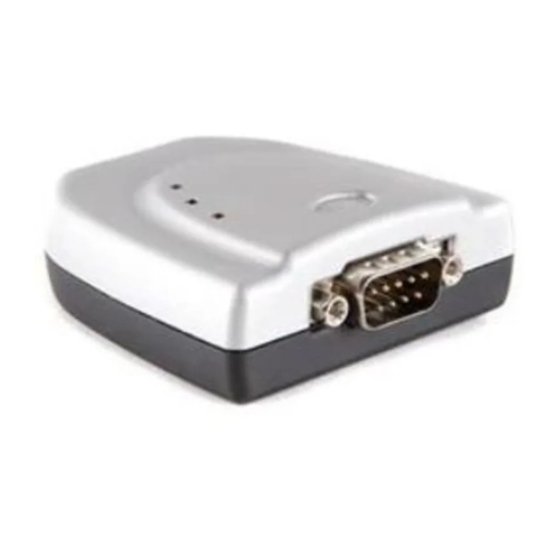
USB2-F-7x01 Full-Speed USB to 1-Port
The USB2-F-7001 and USB2-F-7101 provide a simple method of adapting CANbus devices to USB.
The USB2-F-7101adds optical isolation for the CAN interface.
Flexible mounting options allow the USB2-F-7001 and USB2-F-7101 to be used in a variety of
applications. Indicator LEDs provide functional status.
Unit 1, 2 Seaward Place, Centurion Business Park, Glasgow, G41 1HH, United Kingdom
E-Mail (Support):
Neither the whole nor any part of the information contained in, or the product described in this manual, may be adapted or reproduced
in any material or electronic form without the prior written consent of the copyright holder. This product and its documentat ion are
supplied on an as-is basis and no warranty as to their suitability for any particular purpose is either made or implied. EasySYNC Ltd will
not accept any claim for damages howsoever arising as a result of use or failure of this product. Your statutory rights are not affected.
This product or any variant of it is not intended for use in any medical appliance, device or system in which the failure of the product
might reasonably be expected to result in personal injury. This document provides preliminary information that may be subject to
change without notice. No freedom to use patents or other intellectual property rights is implied by the publication of this document.
EasySYNC Ltd, Unit 1, 2 Seaward Place, Centurion Business Park, Glasgow, G41 1HH, United Kingdom. Scotland Registered Number:
SC224924
EasySYNC Ltd
CANbus Adapter
User Guide
Document Reference No.: ES_000005
Version 1.3
Issue Date: 2010-05-12
EasySYNC Ltd
Tel.: +44 (0) 141 418 0181
support@easysync-ltd.com
Copyright © 2008-2010 EasySYNC Limited
Fax: + 44 (0) 141 418 0110
Web: http://easysync-ltd.com
Advertisement
Chapters
Table of Contents

Related Manuals for EasySync USB2-F-7001


Summary of Contents for EasySync USB2-F-7001
-
Page 1: User Guide
This product and its documentat ion are supplied on an as-is basis and no warranty as to their suitability for any particular purpose is either made or implied. EasySYNC Ltd will not accept any claim for damages howsoever arising as a result of use or failure of this product. -
Page 2: Table Of Contents
Echo / Synchronize (E) ................24 4.1.10 Transmit Standard CAN Frame – 11-bit ID (t) ..........25 4.1.11 Transmit Extended CAN Frame – 29-bit ID (T) ..........26 4.1.12 Get Status Flags (F) ..................27 4.1.13 Get Hardware and Firmware Versions (V) ............28 ©2008 - 2010 EasySYNC Ltd. - Page 3 Device Driver ....................38 Technical Support ....................39 10 Contact Information ..............40 Appendix A – References ..............41 Appendix B – List of Figures and Tables ..........42 Appendix C – Revision History ............43 ©2008 - 2010 EasySYNC Ltd.
-
Page 4: Introduction
Introduction Functional Description The USB2-F-7001 and USB2-F-7101 are USB to CANbus adapters which incorporate the FTDI FT245R USB to FIFO interface IC device. The USB2-F-7101adds optical isolation for the CAN interface. These adapters provide a fast, simple way to CANbus devices to a host PC with a USB port. Throughout this manual, both adapters will be identified as USB2-F-7x01 where common features are identified. -
Page 5: Document Reference No.: Es
CANbus activities Table 1.1 – LED Description Upon initial power up, system reboot or executing the (R)eset command, the LEDs will be in the following state: Green LED = Blinking, Red LED = Single Flash. ©2008 - 2010 EasySYNC Ltd. -
Page 6: Block Diagram
These signals consist of a differential pair, CAN_H and CAN_L. DE-9P Connector (Male) The DE-9P connector is configured in an industry standard (CiA DS102-2) pin-out to provide connection to CANbus peripherals through standard cables. See section 3.1.2. ©2008 - 2010 EasySYNC Ltd. -
Page 7: Features
10Kbps to 1Mbps Table 1.2 – Performance Figures Ordering Information Part Number Description USB2-F-7001 CAN-Plus Full-Speed USB to 1-Port CANbus Adapter USB2-F-7101 CAN-Plus Full-Speed USB to 1-Port CANbus Adapter with optical isolation Table 1.3 – Ordering Information ©2008 - 2010 EasySYNC Ltd. -
Page 8: Installation
Figure 2.2 – USB2-F-7x01 with Rubber Feet 2.1.2 Wiring A standard 0.9m USB “A” to “B” cable is provided. Insert the A-plug into an available USB Host or Hub port. Insert the B-plug into the B-receptacle on the USB2-F-7x01. ©2008 - 2010 EasySYNC Ltd. -
Page 9: Device Driver Installation
2) The device drivers are WHQL-certified and available through the Windows Update service. 3) If you are unable to use the Windows Update service, download the EasySYNC drivers from the website. Extract the files to a folder on your local hard drive. -
Page 10: Figure 2.5 - Device Manager
Figure 2.4 – Device Manager Click on the Plus “+” sign next to the Ports tree to list the available COM port. You will see “EasySYNC USB COM Port”, followed by a COMn assignment. In the figure below, the USB2-F-7x01 is assigned to COM3. -
Page 11: 2.2.2 Mac Os X, Linux, Windows Ce
This USB serial number is different from the CAN Firmware serial number described later in this datasheet. 2.2.2 Mac OS X, Linux, Windows CE Device drivers and FTDI installation guides for Mac OS X, Linux and Windows CE are available for download on the EasySYNC web sites. Firmware Update ©2008 - 2010 EasySYNC Ltd. -
Page 12: Version 1.3
The USB2-F-7x01 firmware can be updated for bug fixes and enhanced features. In order to update the firmware, obtain the updated firmware from the EasySYNC web site and follow the instructions contained in the readme file of the download. ©2008 - 2010 EasySYNC Ltd. -
Page 13: Connections
Ground Signal Ground Bidirectional CAN_H – CANbus high-side signal of differential pair Not Connected Not Connected Shield Case Ground Drain = typically connected to the host PC case Table 3.2 – DE-9P DS102-2 CANbus Pin-Out ©2008 - 2010 EasySYNC Ltd. -
Page 14: Application Programming Interfaces
The CANbus messages are received at all times by default and sent to the host through the FTDI FT245 USB-FIFO interface immediately. Firmware version 2.2 supports sustained read of CAN messages sent 1ms apart as well as a bursts of up to 100 CAN messages sent 50us apart. ©2008 - 2010 EasySYNC Ltd. -
Page 15: Help (H, H Or ?)
B – Enter Bootload Mode L – Set Listen Mode E – Clear Buffers and Echo Char R – Reset USB2-F-7001 H, ? or h – Help on USB2-F-7001 Commands<CR> = OK <BELL> = ERROR ©2008 - 2010 EasySYNC Ltd. -
Page 16: Set Can Channel Timing - Simple (S)
3 = 100Kbps 4 = 125Kbps 5 = 250Kbps 6 = 500Kbps 7 = 800Kbps 8 = 1Mbps Remarks Example: S5<CR> Set CAN transmission rate to 250Kbps Return Codes <CR> = OK <BELL> = ERROR ©2008 - 2010 EasySYNC Ltd. -
Page 17: Set Can Channel Timing - Advanced (S)
Example: s01BE07<CR> Set CAN transmission rate to 250Kbps. NOTE: With this command, multiple combinations of BRGCON1, BRGCON2 and BRGCON3 can yield the same bit rate. Return Codes <CR> = OK <BELL> = ERROR ©2008 - 2010 EasySYNC Ltd. -
Page 18: Set Acceptance Mask (M)
Set Acceptance Mask to check bits 10, 9 and 8 against the filter. Bits 7 thorugh 0 are ignored as “don’t care”. Use the Acceptance Mask in conjunction with the Acceptance Filter, defined next. Return Codes <CR> = OK <BELL> = ERROR ©2008 - 2010 EasySYNC Ltd. -
Page 19: Set Acceptance Filter (M)
Set Acceptance Filter to receive standard messages with the CAN ID of 0x1FF. If used in conjunction with the Acceptance Mask example above, frames of the range 0x100 through 0x1FF will be passed and all other CAN IDs blocked. Return Codes <CR> = OK <BELL> = ERROR ©2008 - 2010 EasySYNC Ltd. -
Page 20: Enable Time Stamp (Z)
0 = disable time stamp feature 1 = enable time stamp feature Remarks Default is OFF (disable time stamp) Only use when required to change functionality. Example: Z1<CR> Enable time stamp. Return Codes <CR> = OK <BELL> = ERROR ©2008 - 2010 EasySYNC Ltd. -
Page 21: Open Can Channel (O)
Once the CAN channel is open, it is necessary to execute the Echo/Synchronize (E or e) command to flush the data buffers. Once the CAN channel is synchronized, received data is automatically sent from the CAN network to the controlling application. Return Codes <CR> = OK <BELL> = ERROR ©2008 - 2010 EasySYNC Ltd. -
Page 22: Open Can Channel For Listen Only (L)
Definition L<CR> Parameters None Remarks Example: L<CR> Open CAN channel in Listen Only mode Received data is automatically sent from the CAN network to the controlling application. Return Codes <CR> = OK <BELL> = ERROR ©2008 - 2010 EasySYNC Ltd. -
Page 23: Close Can Channel (C)
4.1.8 Close CAN Channel (C) Summary Closes the CAN channel. This command provides backward compatibility with some existing CANbus adapters. Definition C<CR> Parameters None Remarks Example: C<CR> Close CAN channel. Return Codes <CR> = OK <BELL> = ERROR ©2008 - 2010 EasySYNC Ltd. -
Page 24: Echo / Synchronize (E)
Clear transmit data buffers. Data buffers should be cleared immediately after opening the CAN channel to prevent erroneous as a result of sending old data in the buffer. Definition E<CR> Parameters None Remarks Example: E<CR> Clear data buffers. Return Codes E<CR> = OK <BELL> = ERROR ©2008 - 2010 EasySYNC Ltd. -
Page 25: Transmit Standard Can Frame - 11-Bit Id (T)
Data = 0x01, 0x23, 0x45, 0x67, 0x89, 0xAB, 0xCD, 0xEF Example: t4560 Transmit an 11-bit ID frame with ID = 0x456 Data = zero bytes (no data) Return Codes z<CR> = OK <BELL> = ERROR ©2008 - 2010 EasySYNC Ltd. -
Page 26: Transmit Extended Can Frame - 29-Bit Id (T)
Data = 0x01, 0x23, 0x45, 0x67, 0x89, 0xAB, 0xCD, 0xEF Example: T123456780 Transmit an 11-bit ID frame with ID = 0x12345678 Data = zero bytes (no data) Return Codes Z<CR> = OK <BELL> = ERROR ©2008 - 2010 EasySYNC Ltd. -
Page 27: Get Status Flags (F)
Will cause RED LED to Single Flash bit 5 = Transmit Bus-OFF: Transmit Error Counter > 255 Will cause RED LED to remain ON bit 6 = Receive Buffer 1 Overflow bit 7 = Receive Buffer 0 Overflow <BELL> = ERROR ©2008 - 2010 EasySYNC Ltd. -
Page 28: Get Hardware And Firmware Versions (V)
Get hardware and firmware version numbers of USB2-F-7x01. Each value consists of a two-digit, binary coded decimal (BCD) number. Definition V<CR> Parameters None Remarks Example V<CR> Get serial number Return Codes Vxxyy<CR> = OK xx = hardware version yy = firmware version <BELL> = ERROR ©2008 - 2010 EasySYNC Ltd. -
Page 29: Get Serial Number (N)
Get serial number of USB2-F-7x01. Definition N<CR> Parameters None Remarks Example N<CR> Get serial number Return Codes Nxxxx<CR> = OK xxxx = serial number of the USB2-F-7x01. It is possible to have alphanumeric values. <BELL> = ERROR ©2008 - 2010 EasySYNC Ltd. -
Page 30: Reset Microcontroller (R)
Resets PIC18F2680 MCU. Configurations are preserved in EEPROM. This command is useful if the USB2-F-7x01 becomes unresponsive. LEDs will be in the state mentioned in Section 1.2. Definition R<CR> Parameters None Remarks Example R<CR> Reset PIC18F2680 Return Codes <CR> = OK. <BELL> = ERROR ©2008 - 2010 EasySYNC Ltd. -
Page 31: Prepare Bootloader (B)
Resets PIC18F2680 MCU into Bootloader mode. Only use this command immediately prior to loading new firmware onto the USB2-F-7x01. Definition B<CR> Parameters None Remarks Example B<CR> Prepare to load new firmware Return Codes Entering Bootloader Mode… Boot:> <BELL> = ERROR ©2008 - 2010 EasySYNC Ltd. -
Page 32: Electrical Details
Table 5.2 – CANbus Electrical Details Optical Isolation (USB2-F-7101 only) Parameter Description Minimum Typical Maximum Units Conditions Dielectric Insulation 1 Minute Duration 2,000 Voltage Table 5.3 – Optical Isolation Electrical Details (USB2-F-7101 only) ©2008 - 2010 EasySYNC Ltd. -
Page 33: Mechanical Details
Document Reference No.: ES_000005 USB2-F-7x01 Full-Speed USB to 1-Port CANbus Adapter User Guide Version 1.3 Clearance No.: ES#02 Mechanical Details Module Mechanical Dimensions Figure 6.1 – USB2-F-7x01 Case Dimensions ©2008 - 2010 EasySYNC Ltd. -
Page 34: Uniclip™ Mechanical Dimensions
Document Reference No.: ES_000005 USB2-F-7x01 Full-Speed USB to 1-Port CANbus Adapter User Guide Version 1.3 Clearance No.: ES#02 UniClip™ Mechanical Dimensions Figure 6.2 – USB2-F-7x01 Case Dimensions with UniClip ©2008 - 2010 EasySYNC Ltd. -
Page 35: Physical Environment Details
Typical Maximum Units Conditions Storage Temperature Range Table 7.1 – Storage Temperature Operating Parameter Description Minimum Typical Maximum Units Conditions Operating Temperature 5% to 95% RH, –40 Range non condensing Table 7.2 – Operating Temperature ©2008 - 2010 EasySYNC Ltd. -
Page 36: Environmental Approvals & Declarations
The USB2-F-7x01 is designed as a robust USB-Serial adapter for use in many environments. There are no user-serviceable parts. Any failure will require a replacement of the unit. 8.4.1 Mean Time To Failure (MTTF) The MTTF is TBD. ©2008 - 2010 EasySYNC Ltd. -
Page 37: Import / Export Information
Document Reference No.: ES_000005 USB2-F-7x01 Full-Speed USB to 1-Port CANbus Adapter User Guide Version 1.3 Clearance No.: ES#02 Import / Export Information Import / Export Information for USB2-F-7001 and USB2-F-7101 Country of Origin China Harmonized Code 8471.80.1000 Product Description USB to CANbus Computer Adapter, Single Port USA ECCN EAR99 –... -
Page 38: Troubleshooting
Serial Enumerator option, also found on the advanced driver options screen in Figure 2.13. COM PORT IN USE: Windows keeps track of all COM port assignments. If multiple EasySYNC products have been connected to a single system, the COM port number will increase, even if the other devices are not attached. -
Page 39: Technical Support
Technical support may be obtained from your nearest EasySYNC office: United Kingdom: support@easysync.co.uk United States: support@easysync-ltd.com Application Notes and support documentation For further CAN support documentation, refer to the following EasySYNC CAN programmers guide, application and technical notes: PG_USB2-F-7x01_API_Guide.pdf AN_102_CAN_Plus_Custom_CAN_Data_Rates.pdf AN_103_CAN_Plus_Message_Filtering.pdf TN_101_EasySync_CAN_Plus_Migration_Guide.pdf... -
Page 40: Contact Information
7235 NW Evergreen Parkway, Suite 600 Hillsboro, OR 97123-5803 Tel: +1 (503) 547 0909 Fax: +1 (503) 547 0990 E-Mail (Sales) sales@easysync-ltd.com E-Mail (Support) support@easysync-ltd.com E-Mail (General Inquiries) admin@easysync-ltd.com Web Site URL http://easysync-ltd.com Web Shop URL http://easysync-ltd.com ©2008 - 2010 EasySYNC Ltd. -
Page 41: Appendix A - References
USB2-F-7x01 Full-Speed USB to 1-Port CANbus Adapter User Guide Version 1.3 Clearance No.: ES#02 Appendix A – References Bosch CAN Specification, Version 2.0: http://www.semiconductors.bosch.de/pdf/can2spec.pdf CAN in Automation (CiA): www.can-cia.org Future Technology Devices International Ltd. (FTDI) www.ftdichip.com Microchip www.microchip.com ©2008 - 2010 EasySYNC Ltd. -
Page 42: Appendix B - List Of Figures And Tables
Table 5.2 – CANbus Electrical Details ............... 32 Table 5.3 – Optical Isolation Electrical Details (USB2-F-7101 only) ......32 Table 7.1 – Storage Temperature ................35 Table 7.2 – Operating Temperature ................35 Table 8.1 – Import / Export Information ..............37 ©2008 - 2010 EasySYNC Ltd. -
Page 43: Appendix C - Revision History
Appendix C – Revision History Version 1.0 Initial Release April 2009 Version 1.01 Added reference to USB2-F-7001 API Guide 2009 Version 1.02 Corrected Get Flags “F” command return value 2009 Version 1.1 Changed “Acceptance Code” to “Acceptance Filter” throughout the document.
Need help?
Do you have a question about the USB2-F-7001 and is the answer not in the manual?
Questions and answers