Sony DVMC-DA1 Service Manual
Hide thumbs
Also See for DVMC-DA1:
- Operating instructions manual (46 pages) ,
- Operating instructions manual (47 pages)
Table of Contents
Advertisement
Quick Links
SERVICE MANUAL
Power requirements
DC IN 6V jack accepts the AC-MZ60A AC power adapter
(supplied), AC 120 V, 60 Hz
Power consumption
AC 120 V, 60 Hz, 5.1 W (max., AC power adapter)
Operating temperature
10°C to 35°C (50°F to 95°F)
Operating humidity
40 % to 80 %
Storage temperature
–20°C to 80°C (–4°F to 176°F)
Storage humidity
20 % to 80 %
Dimensions (approx.)
124 × 44 × 90.5 mm (5 × 1
(w/h/d, excluding projections)
Mass (approx.)
300 g (10 oz) (unit only)
9-928-112-11
SPECIFICATIONS
× 3
3
5
/
/
inches)
4
8
DVMC-DA1
Input/output connector
S-VIDEO IN: Mini DIN 4-pin (1)
S-VIDEO OUT: Mini DIN 4-pin (1)
VIDEO IN: RCA pin (1)
VIDEO OUT: RCA pin (1)
AUDIO IN: RCA pin (2): L, R
AUDIO OUT: RCA pin (2): L, R
DV IN/OUT: S100 (100 Mbps) 4-pin (1)
Supplied accessories
AC power adapter (AC-MZ60A)
DV connecting cable
Audio/video connecting cable
S-video connecting cable
Operating instructions
Owner registration card
Warranty card
Important safe guard
Design and specifications are subject to change without
notice.
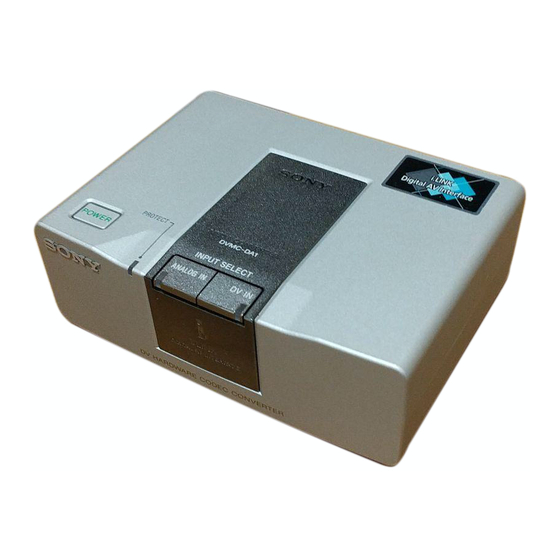
MEDIA CONVERTER
US Model
Canadian Model
Advertisement
Table of Contents

Subscribe to Our Youtube Channel
Related Manuals for Sony DVMC-DA1


Summary of Contents for Sony DVMC-DA1
-
Page 1: Media Converter
DVMC-DA1 SERVICE MANUAL US Model Canadian Model SPECIFICATIONS Input/output connector Power requirements S-VIDEO IN: Mini DIN 4-pin (1) DC IN 6V jack accepts the AC-MZ60A AC power adapter S-VIDEO OUT: Mini DIN 4-pin (1) (supplied), AC 120 V, 60 Hz... -
Page 2: Table Of Contents
MARK ! ON THE SCHEMATIC DIAGRAMS AND IN THE PARTS LIST ARE CRITICAL TO SAFE OPERATION. REPLACE THESE CRITIQUES POUR LA SÉCURITÉ DE FONCTIONNEMENT. NE REMPLACER CES COMPOSANTS QUE PAR DES PIÈSES SONY COMPONENTS WITH SONY PARTS WHOSE PART NUMBERS DONT LES NUMÉROS SONT DONNÉS DANS CE MANUEL OU APPEAR AS SHOWN IN THIS MANUAL OR IN SUPPLEMENTS PUBLISHED BY SONY. - Page 3 Table of contents Locating the parts and controls Locating the parts and controls 1-1 Front Overview 1-2 1 POWER button Checking the supplied parts and Turns on/off the media converter. accessories 1-3 2 PROTECT indicator Duplicating analog video to digital Lights when the input picture includes video 1-3 a copy protection signal.
-
Page 4: Overview
(page 13, 14) You can capture images from an analog video unit connected to your The DVMC-DA1 is a media converter unit which converts analog video PC via the media converter using the DV (i.Link) connector. signals to digital video signals and vice versa. -
Page 5: Checking The Supplied Parts And Accessories
Check to make sure you have received the following Connecting an analog video unit and items in the carton. a DV unit via the media converter If something is missing, contact your Sony dealer or service facility. to Audio/video output to DV input/output... -
Page 6: Duplicating Analog Video To Digital Video
Duplicating analog video to digital video (continued) Duplicating digital video to analog If you want to convert digital video to analog video video Make the connection as follows: You can convert and record pictures and sound from a DV unit to an analog video unit by connecting both •... -
Page 7: Viewing Digital Video On Your Tv
Viewing digital video Viewing digital video on your TV (continued) Viewing digital video on your TV on your TV You can enjoy high quality digital video when you connect the DV unit to the TV via the media converter. Connecting a DV unit and a TV via the media converter Press POWER to turn on the media converter. -
Page 8: Connecting A Pc And An Analog Video Unit Via The Media Converter
Capturing images from an analog Capturing images from an analog video unit using a PC (continued) z Tip video unit using a PC If you want to convert digital video to analog The DV still image video capture card kit DVBK- Make the connection as follows: Connecting a PC and an analog video CW200 for PC/AT... -
Page 9: Precautions
Have the product checked and cord, pull it out by the plug. Never pull the cord itself. repaired at your Sony dealer or local authorized Sony • Do not overload wall outlets, extension cords, or service facility. -
Page 10: Technical Information
Technical information Technical information (continued) Output/input of analog video signals Depending on the connection of VIDEO IN or S- Signal flows VIDEO connector, the output signal changes as follows. The signal flow of the media converter and the connected unit is illustrated below: The input signal is coming from only the VIDEO IN connector When the media converter is turned off (with... -
Page 11: Dv Recording Format
Technical information (continued) Macrovision This product incorporates copyright protection technology that is protected by method claims of certain U.S. patents and other intellectual property rights owned by Macrovision 12-bit/16-bit audio modes Corporation and other rights owners. Use of this copyright protection technology must be authorized by Macrovision 16-bit mode Corporation, and is intended for home and other limited... -
Page 12: Block Diagrams
DVMC-DA1 SECTION 2 BLOCK DIAGRAMS 2-1. OVERALL BLOCK DIAGRAM IFX-52 BOARD IC102 IC401 IC501 IC503 J802 CN801 LINE V VIDEO IN Y0-Y7 V BUS L BUS TPA+, TPA–, TPB+, TPB– DV IN/OUT • AGC, AFC, BLOCKING DCT/IDCT DV INTERFACE A-D CONV. -
Page 13: Power Block Diagram
DVMC-DA1 2-2. POWER BLOCK DIAGRAM IFX-52 BOARD IC301 Q302 L401, L403 SWITCHING L305 L313 VFD 3V EVER 5V DC-DC CONV. IC101 FL101 IC401 L106 LF301 FB301 FL301 FB302 F301 L312 SW 3V EVER 5V AU D302 J301 VCC1 OUT1 BLOCKING... -
Page 14: Printed Wiring Boards And Schematic Diagrams
DVMC-DA1 SECTION 3 PRINTED WIRING BOARDS AND SCHEMATIC DIAGRAMS • Waveform THIS NOTE IS COMMON FOR WIRING BOARDS AND SCHEMATIC DIAGRAMS IC001 !§ YOUT IC401 %º SPCK(CL403) (In addition to this, the necessary note is printed in each block) (For printed wiring boards) 3Vp-p •... -
Page 15: Swx-22 (Switch) Schematic Diagram
DVMC-DA1 SWX-22 (SWITCH) SCHEMATIC DIAGRAM (Page 3-16) SWITCH SWX-22... -
Page 16: Swx-22 (Switch) Printed Wiring Board
DVMC-DA1 SWX-22 (SWITCH) PRINTED WIRING BOARD There are few cases that the part printed on this diagram isn’t mounted in this model. SWITCH SWX-22... - Page 17 DVMC-DA1 IFX-52 (MAIN : SIDE A) PRINTED WIRING BOARD There are few cases that the part printed on this diagram isn’t mounted in this model. IFX-52 BOARD D302 C-1 D303 C-2 D304 C-1 D702 B-6 D703 C-8 D705 C-8 D706 C-8...
- Page 18 DVMC-DA1 IFX-52 (MAIN : SIDE B) PRINTED WIRING BOARD There are few cases that the part printed on this diagram isn’t mounted in this model. IFX-52 BOARD CN701 C-1 CN801 F-7 CN905 B-7 D101 E-1 D102 E-1 D501 D-6 D701 A-3...
-
Page 19: Ifx-52 (J Core) Schematic Diagram
DVMC-DA1 IFX-52 (J CORE) SCHEMATIC DIAGRAM • Refer to page 3-5, 3-7 for IFX-52 BOARD printed wiring board. TO JACK TO AUDIO TO DC CON TO MECH CON J CORE 3-10 IFX-52... -
Page 20: Ifx-52 (Vfd) Schematic Diagram
DVMC-DA1 IFX-52 (VFD) SCHEMATIC DIAGRAM • Refer to page 3-5, 3-7 for IFX-52 BOARD printed wiring board. TO DC CON TO AMP TO AGC TO AGC TO MECH CON 3-11 3-12 IFX-52... -
Page 21: Ifx-52 (Mech Con) Schematic Diagram
DVMC-DA1 IFX-52 (MECH CON) SCHEMATIC DIAGRAM • Refer to page 3-5, 3-7 for IFX-52 BOARD printed wiring board. TO DC CON TO AUDIO TO AGC TO AMP TO AUDIO TO AGC MECH CON 3-13 3-14 IFX-52... -
Page 22: Ifx-52 (Hi) Schematic Diagram
DVMC-DA1 IFX-52 (HI) SCHEMATIC DIAGRAM • Refer to page 3-5, 3-7 for IFX-52 BOARD printed wiring board. TO MECH CON (Page 3-2) TO MECH CON TO DC CON TO AUDIO TO AUDIO TO AMP TO AUDIO TO AMP TO AGC... -
Page 23: Ifx-52 (Dc Con) Schematic Diagram
DVMC-DA1 IFX-52 (DC CON) SCHEMATIC DIAGRAM • Refer to page 3-5, 3-7 for IFX-52 BOARD printed wiring board. DC CON F302 1.4A TO AMP TO AUDIO TO AGC TO AMP TO AUDIO TO AGC MECH CON DC CON 3-17 3-18... -
Page 24: Ifx-52 (Amp) Schematic Diagram
DVMC-DA1 IFX-52 (AMP) SCHEMATIC DIAGRAM • Refer to page 3-5, 3-7 for IFX-52 BOARD printed wiring board. TO AGC TO JACK DC CON TO JACK TO DC CON TO MECH CON TO JACK TO MECH CON 3-19 3-20 IFX-52... -
Page 25: Ifx-52 (Agc) Schematic Diagram
DVMC-DA1 IFX-52 (AGC) SCHEMATIC DIAGRAM • Refer to page 3-5, 3-7 for IFX-52 BOARD printed wiring board. TO DC CON TO DC CON TO DC CON TO AMP TO MECH CON 3-21 3-22 IFX-52... -
Page 26: Ifx-52 (Audio) Schematic Diagram
DVMC-DA1 IFX-52 (AUDIO) SCHEMATIC DIAGRAM • Refer to page 3-5, 3-7 for IFX-52 BOARD printed wiring board. TO JACK ANALOG IN DV IN TO DC CON TO MECH CON MECH CON TO MECH CON AUDIO 3-23 3-24 IFX-52... -
Page 27: Ifx-52 (Jack) Schematic Diagram
DVMC-DA1 IFX-52 (JACK) SCHEMATIC DIAGRAM • Refer to page 3-5, 3-7 for IFX-52 BOARD printed wiring board. IFX-52 (CN) SCHEMATIC DIAGRAM • Refer to page 3-5, 3-7 for IFX-52 BOARD printed wiring board. JACK TO DC CON TO AMP TO MECH CON... - Page 28 DVMC-DA1 SECTION 4 ADJUSTMENTS 4-1. PREPARATIONS BEFORE ADJUSTMENTS Use the following measuring instruments for video section adjustment. 1. Equipment Required 2. Removing Cabinets and Connections TV monitor Remove the four screws from the bottom panel and remove Oscilloscope (dual-trace, band width of 30 MHz more with the cabinet (upper) block assembly.
- Page 29 Fig.4-2 shows the 75% color bar signals recorded on the alignment tape for Audio Operation Check. Note: Measure with video terminal (Terminated at 75 Ω) White (100%) White (75%) Burst signal 0.714V (75%) 0.286V Black 0.286V White (100%) Horizontal sync signal Color bar signal waveform Color bar pattern Fig.
- Page 30 4-2. INITIALIZATION OF C PAGE DATA 1. Initializing the C Page Data 3. C Page Table Note: If the page C data is initialized, the following adjustments must be Note: Fixed data-1 : Initialized data. (Refer to “1. Initializing the C Page performed again.
- Page 31 4-3. INITIALIZATION OF D PAGE DATA 3. D Page Table 1. Initializing the D Page Data Note: If the page D data is initialized, the following adjustments must be Note: Fixed data-1 : Initialized data. (Refer to “1. Initializing the D Page performed again.
- Page 32 4-4. VIDEO SYSTEM ADJUSTMENTS Connection of Video System Measuring Instruments Connect the video system measuring instruments as shown in Fig. 4-3. Pattern generator TV monitor Video out Video in S video out Oscilloscope VIDEO Fig. 4-3 When the page: 3, address: 0C data is 04: 1.
- Page 33 2. S-VIDEO OUT Y Level Adjustment 3. S-VIDEO OUT Cr, Cb Level Adjustment Mode VTR, Digital EE Mode VTR, Digital EE Signal No signal Signal No signal Measurement Point Y signal terminal of S VIDEO jack Measurement Point Chroma signal terminal of S VIDEO (75 Ω...
- Page 34 4. VIDEO OUT Sync Level and Burst Level Check 5. PLL Adjustment Set the VCO center level of the video input circuit (IC102). Mode Digital EE Mode Digital EE Signal No signal Signal Color bar (VIDEO IN terminal innput) Measurement Point Measurement Point Video out <3.579545 MHz ±10Hz>...
-
Page 35: Service Mode
4-5. SERVICE MODE 2. Precautions upon using ADJUSTMENT REMOTE COMMANDER the adjustment remote commander The adjustment remote commander is used for changing the Mishandling of the adjustment remote commander may erase the calculation coefficient in signal processing, EVR data, etc. The correct adjustment data at times. -
Page 36: Repair Parts List
4-979-367-01 SCREW (M2 × 6) X-4621-825-1 CABINET (LOWER) ASSY 4-639-053-01 SHIELD (LOWER) A-8044-701-A CABINET (UPPER) BLOCK ASSY A-8054-856-A IFX-52 BOARD, COMPLETE 4-942-636-21 EMBLEM (NO.3.5), SONY 4-982-491-01 SCREW (2 × 8), TAPPING A-8054-858-A SWX-22 BOARD, COMPLETE 7-685-647-74 +BV 3 × 10 1-790-197-11 FFC (IF-SW) -
Page 37: Electrical Parts List
IFX-52 5-2. ELECTRICAL PARTS LIST NOTE: • Due to standardization, replacements in the • CAPACITORS: • SEMICONDUCTORS parts list may be different from the parts uF: µF In each case, u: µ, for example: specified in the diagrams or the components •... - Page 38 IFX-52 Ref. No. Part No. Description Remarks Ref. No. Part No. Description Remarks C243 1-164-943-11 CERAMIC CHIP 0.01uF C405 1-162-970-11 CERAMIC CHIP 0.01uF C244 1-135-259-11 TANTAL. CHIP 10uF 6.3V C406 1-109-982-11 CERAMIC CHIP C245 1-135-259-11 TANTAL. CHIP 10uF 6.3V C407 1-164-943-11 CERAMIC CHIP 0.01uF C247...
- Page 39 IFX-52 Ref. No. Part No. Description Remarks Ref. No. Part No. Description Remarks D706 8-719-064-61 DIODE 01BZA8.2 (TE85L) IC503 8-759-566-52 IC SN104266PN-TEB D707 8-719-064-61 DIODE 01BZA8.2 (TE85L) IC601 8-759-566-25 IC MB91191PFF-G-119-BND-ER D801 8-719-064-61 DIODE 01BZA8.2 (TE85L) IC602 8-759-445-94 IC AK6480AM-E2 IC701 8-759-424-79 IC S-8423YFS-T2 <...
- Page 40 IFX-52 Ref. No. Part No. Description Remarks Ref. No. Part No. Description Remarks < TRANSISTOR > R023 1-218-961-11 RES,CHIP 4.7K 1/16W R024 1-218-961-11 RES,CHIP 4.7K 1/16W Q003 8-729-037-72 TRANSISTOR UN9211J-(K8).SO R028 1-218-953-11 RES,CHIP 1/16W Q004 8-729-037-52 TRANSISTOR 2SD2216J-QR(K8).SO R029 1-218-957-11 RES,CHIP 2.2K 1/16W Q101...
- Page 41 IFX-52 Ref. No. Part No. Description Remarks Ref. No. Part No. Description Remarks R310 1-218-957-11 RES,CHIP 2.2K 1/16W R506 1-218-990-11 SHORT R312 1-208-701-11 RES,CHIP 5.6K 0.50% 1/16W R507 1-218-990-11 SHORT R313 1-218-974-11 RES,CHIP 1/16W R508 1-218-990-11 SHORT R315 1-218-955-11 RES,CHIP 1.5K 1/16W R509...
- Page 42 IFX-52 SWX-22 Ref. No. Part No. Description Remarks Ref. No. Part No. Description Remarks R729 1-218-949-11 RES,CHIP 1/16W < DIODE > R734 1-218-990-11 SHORT R736 1-218-990-11 SHORT D901 8-719-991-27 DIODE CL-170G-CD-T (DV IN) R737 1-218-973-11 RES,CHIP 1/16W D902 8-719-027-84 DIODE CL-155UR/G-DT (PROTECT) R739 1-218-953-11 RES,CHIP 1/16W...
- Page 43 DVMC-DA1 Sony Corporation 98K16026-1 Information Technology Company 9-928-112-11 Printed in Japan ©1998.11 — 58 — Published by Technical Response Center...
Need help?
Do you have a question about the DVMC-DA1 and is the answer not in the manual?
Questions and answers