Table of Contents
Advertisement
Quick Links
Installation Manual
TANKLESS GAS WATER HEATER
Potential dangers from accidents during installation and use are divided into the following three
categories. Closely observe these warnings, they are critical to your safety.
DANGER
WARNING
CAUTION
WARNING:
If the information in this manual is not followed exactly, a fire or explosion may result
causing property damage, personal injury or death.
Prohibited
Requests to Installers
• In order to use the water heater safely, read this installation manual carefully, and follow the
installation instructions.
• Failures and damage caused by erroneous work or work not as instructed in this manual are not
covered by the warranty.
• Check that the installation was done properly in accordance with this Installation Manual upon
completion.
• After completing installation, please either place this Installation Manual in a plastic pouch and
attach it to the side of the water heater (or the inside of the pipe cover or recess box if applicable),
or hand it to the customer to retain for future reference. Also, be sure to fill in all of the required
items on the warranty and to hand the warranty to the customer along with the Owner's Guide.
CERTIFIED
R
SAR8563-6
Rev. 08/08
N-0751M-DV
DANGER indicates an imminently hazardous situation which,
if not avoided, will result in death or serious injury.
WARNING indicates a potentially hazardous situation which,
if not avoided, could result in death or serious injury.
CAUTION indicates a potentially hazardous situation which,
if not avoided, may result in minor or moderate injury.
Disconnect
Power
Low NOx
Approved by
SCAQMD
Accepted For Use
City of New York
Department of Buildings
MEA 19-03-E
(Indoor Installation)
Ground
CAUTION
FOR USE IN RESIDENTIAL, COMMERCIAL, OR MANUFACTURED
HOME APPLICATIONS.
Installation must conform with local codes, or in the absence of local codes,
the National Fuel Gas Code, ANSI Z223.1/NFPA 54- latest edition and/or CSA
B149.1, Natural Gas and Propane Installation Code (NSCNGPIC).
When applicable, installation must conform with the Manufactured
Home Construction and Safety Standard, Title 24 CFR, Part 3280 or the
Canadian Standard CAN/CSA-Z240 MH Mobile Homes, Series M86.
Noritz America reserves the right to discontinue, or change at any
time, the designs and/or specifications of its products without notice.
NORITZ AMERICA
CORPORATION
Be sure to do
*SAR8563 C*
Advertisement
Table of Contents

Related Manuals for Noritz N-0751M-DV


Summary of Contents for Noritz N-0751M-DV
- Page 1 Installation Manual NORITZ AMERICA CORPORATION TANKLESS GAS WATER HEATER N-0751M-DV (Indoor Installation) Potential dangers from accidents during installation and use are divided into the following three categories. Closely observe these warnings, they are critical to your safety. DANGER indicates an imminently hazardous situation which, DANGER if not avoided, will result in death or serious injury.
-
Page 2: Included Accessories
The following accessories are included with the unit. Included Accessories Check for any missing items before starting installation. Part Shape Part Shape Q’ty Q’ty Owner's Guide, Warranty, Tapping Screw Installation Manual each (this document) Remote Controller Remote Controller (See p. 20) Cord (10ft) The accessories listed below are not Optional Accessories... -
Page 3: Quick Connect Multi System Installation
Quick Connect Multi System Installation • The Quick Connect Multi System allows the installation of two units together utilizing only the Quick Connect Cord. The Quick Connect Cord is 6 ft. long. Install the units 2-19" apart from each other to ensure the cord will be able to reach between the units. -
Page 4: Before Installation
Check the Gas • Check that the rating plate indicates the correct type of gas. N-0751M-D N-0751M-DV 199,900 BTU 199,900 BTU • Check that the gas supply line is sized for 12,000 BTU 12,000 BTU 199,900 Btuh for this unit. -
Page 5: Choosing Installation Site
Choosing Installation Site * Locate the appliance in an area where leakage from the unit or connections will not result in damage to the area adjacent to the appliance or to the lower floors of the structure. When such locations cannot be avoided, it is recommended that a suitable drain pan, adequately drained, be installed under the appliance. - Page 6 CAUTION • Avoid installation above gas ranges or stoves. • Avoid installation between the kitchen fan and stove. If oily fumes or a large amount of steam are present in the installation location, take measures to prevent the fumes and steam from Prohibited entering in the equipment.
-
Page 7: Installation Clearances
Installation Clearances WARNING Before installing, check for the following: Install in accordance with relevant building and mechanical codes, as well as any local, state or national regulations, or in the absence of local and state codes, to the National Fuel Gas Code ANSI Z223.1/NFPA 54 –... -
Page 8: Securing To The Wall
Clearance Requirements from Vent Terminations to Building Openings * All clearance requirements are in accordance with ANSI Z21.10.3 and the National Fuel Gas Code, ANSI Z223.1 and in Canada, in accordance with NSCNGPIC. Vent Terminal Area Where Terminal is Not Permitted Air Supply Inlet Clearance Above grade, veranda, porch, deck,... -
Page 9: Vent Pipe Installation
• The weight of the device will be applied to the wall. If the strength of the wall is not suffi- cient, reinforcement must be done to prevent the transfer of vibration. • Do not drop or apply unnecessary force to the device when installing. Internal parts may be damaged and may become highly dangerous. - Page 10 Vent Terminal Installation Precautions Note the following vent terminal installation requirements • Do not install the vent terminal indoors • Install the vent terminal with a downward slope upward downward slope slope • Avoid storing hazardous • Install with the proper length protruding through the wall objects near the terminal Gasoline Proper installation.
- Page 11 • Do not store hazardous or flammable sub- Venting Precautions stances near the vent terminal, • Use 4" diameter Category III vent pipe. • Slope the intake and exhaust pipes downwards • Maximum vent length 1/4" for every 12" towards the termination. •...
- Page 12 Vertical Vent Termination Exhaust 1-2' RainCap • Terminate at least 6' from the Intake Air combustion air intake of any Min. Storm appliance, and 3' from any Collar other building opening, gas Roof Flashing utility meter, service regulator etc. Roof Jack •...
-
Page 13: Gas Piping
1/8" NPT screw with an allen wrench and connecting the appropriate pressure gauge. Instructions Sample Gas Line 1. Size each outlet branch starting from the furthest Noritz N-0751M-DV using the Btuh required and the length from the Barbecue (199,900 Btuh) meter. (50,000 Btuh) Outlet E 2. - Page 14 Gas Line Sizing for a Noritz N-0751M-DV Adapted from UPC 1997 Maximum Natur Natural Gas Delivery Capacity in Cubic Feet per Hour (0.60 Specific Gravity, 0.5" WC Pressure Drop) Length in Feet Pipe 100' 125' Size 1/2" 3/4" 1" 1 1/4"...
-
Page 15: Water Piping
Installation and service must be performed by a qualified plumber. In the Water Piping Commonwealth of Massachusetts, this product must be installed by a licensed plumber or gas fitter in accordance with the Massachusetts Plumbing and Fuel Gas Code 248 CMR Sections 2.00 and 5.00. Observe all applicable codes. This appliance suitable for potable water and space heating applications. - Page 16 Supply water piping Hot water piping • Do not use PVC, iron, or any piping which has been • Do not use lead, PVC, iron or any piping which treated with chromates, boiler seal or other chemicals. has been treated with chromates, boiler seal or •...
-
Page 17: Water Treatment
*Install Noritz Isolation Valves to allow for flushing. **Flushing is required if a water softener is not installed. Water Treatment System Shutoff Valve City Water Supply Cold to Water NORITZ Heater N-0751M-DV Optional Sediment Filter Pressure Shutoff Valve Relief Valve Water Treatment Device... -
Page 18: Plumbing Applications
Plumbing Applications Recirculation System Notes: 1. Size the pump to provide a maximum of 2 GPM through the system at 10 ft of head plus piping NORITZ losses. Hot Water Return Tankless Gas Adjust the flow using a globe valve and verify the Cold Water Supply Water Heater flow rate with the maintenance monitors. -
Page 19: Electrical Wiring
Consult a qualified electrician Electrical Wiring for the electrical work. Do not connect electrical power to the unit until all electrical wiring has been completed. Disconnect Power This appliance must be electrically grounded in accordance with local codes, or in the absence of local codes, with the National Electrical Code, ANSI/NFPA 70. -
Page 20: Remote Controller
To keep the water heater off, let the unit sit for 30 sec. to return to the original display. • The N-0751M-DV can be programmed so that it will default to one of four temperatures if the remote controller is removed (180, 140, 130, 120°F). To change the default temperature, connect the tempera- ture selection wire as shown in the above diagram. -
Page 21: Connecting Remote Controller Cord To Unit
Connecting Remote Controller Cord to Unit • Keep the remote controller cord away from the freeze prevention heaters in the unit. • Tie the redundant cord outside the water heater. Do not put the extra length inside the equipment. • The remote controller cord can be extended up to 300' with 18AWG wire. •... -
Page 22: Pump Wiring
* This feature is not available when using the Quick Con- Pump Wiring nect Multi System feature. Connecting the pump control wire 1. Leave enough slack so that the pump control wires will stay connected if the unit is removed Pump Control from the wall. -
Page 23: Connecting Quick Connect Cord
For Quick Connect Multi System Installation Connecting Quick Connect Cord usa a Quick Connect Cord (sold separately). Caution The wire coloring on the Quick Connect Cord will not be the same as the wire coloring of the connection plug inside the unit. 1.Red 1.Red 1.White... -
Page 24: Maintenance
Periodically check the following to ensure proper Maintenance operation of the water heater. • The venting system must be examined periodically by a qualified service technician to check for any leaks or corrosion. • The burner flame must be checked periodically for a proper blue color and consistency. •... -
Page 25: Lighting Instructions
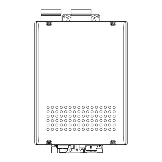
CAUTION Handling after trial operation • If the unit will not be used immediately, close off all gas and water shutoff valves, drain all of the water out of the unit and the plumbing system to prevent the unit and system from freezing, and bleed the gas out of the gas line. - Page 26 Dimensions N-0751M-DV < inch > 17.7" 4- 0.5" 6-0.24 x 0.4"OBLONG HOLE 18.3" 17.6" 6.7" 5.5" 5.9" 9.1" 9.4" 0.4" 3.9" 4" 4" 3.7" 1.1" 2.8" AIR INLET FLUE COLLAR 1.4" 0.4" 1.4" 2.8" WIRING THROUGHWAY 3.9" GAS INLET 5.5"...
- Page 27 Remote Controller RC-7649M carefully before carrying out installation. Installation Guide NORITZ AMERICA CORPORATION Note Do not connect power to the water heater before the remote controller has been properly installed. Recommended installation location of the remote controller is in a bathroom.
- Page 28 Installation 3. Remove the cover of the remote control, 1. Apply Wall Packing to the rear side of the remote controller. mark the location of the screw holes, and drill holes for the wall anchors. 2. Connect the remote controller wires to the 4.
Need help?
Do you have a question about the N-0751M-DV and is the answer not in the manual?
Questions and answers