Table of Contents
Advertisement
Advertisement
Table of Contents

Related Manuals for Teltonika RUT550


Summary of Contents for Teltonika RUT550
- Page 1 USER MANUAL...
-
Page 2: Legal Notice
Copyright © 2013 TELTONIKA Ltd. All rights reserved. Reproduction, transfer, distribution or storage of part or all of the contents in this document in any form without the prior written permission of TELTONIKA Ltd is prohibited. The manufacturer reserves the right to modify the product and manual for the purpose of technical improvement without prior notice. -
Page 3: Table Of Contents
Table of Contents Legal notice ..................................2 Attention .................................... 2 SAFETY INFORMATION ..............................5 Device connection ................................. 6 Introduction ..................................7 Specifications: ................................7 LAN and Wi-Fi: ................................7 LTE ....................................7 UMTS ..................................7 GSM/GPRS/EDGE ............................... 7 Electrical, Mechanical & Environmental: ........................8 Applications ................................ - Page 4 Wireless ................................... 42 Backup WAN ................................45 Firewall ..................................47 Static Routes ................................49 Diagnostics ................................50 Services ..................................50 PING Reboot ................................50 SMS Reboot ................................51 Status via SMS ................................52 NTP ................................... 52 Dynamic DNS................................53 Wireless hotspot ..............................54 OpenVPN ..................................
-
Page 5: Safety Information
SAFETY INFORMATION In this document you will be introduced on how to use a RUT550 router safely. We suggest you to adhere to the following recommendations in order to avoid personal injuries and or property damage. You have to be familiar with the safety requirements before using the device! To avoid burning and voltage caused traumas, of the personnel working with the device, please follow these safety requirements. -
Page 6: Device Connection
Device connection... -
Page 7: Introduction
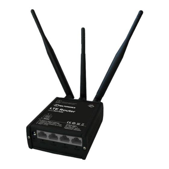
Thank you for purchasing a RUT550 LTE router! RUT550 is part of the RUT5xx series of compact mobile routers with high speed wireless and Ethernet connections. This router is ideal for people who‘d like to share their internet on the go, as it is not restricted by a cumbersome cable connection. -
Page 8: Electrical, Mechanical & Environmental
Power Class 1 (1 W, 30 dBm) GSM/GPRS 1800/1900 Mhz Power Class E2 (0.5 W, 27 dBm) for EDGE 850/900 MHz GPRS: 85.6 kbps DL/85.6 kbps UL (class 12) EDGE: 236.8 kbps DL/236.8 kbps UL (class 12) Electrical, Mechanical &... -
Page 9: Applications
Applications... -
Page 10: Setting Up Your Router
Setting up your router Installation After you unpack the box, follow the steps, documented below, in order to properly connect the device. For better Wi- Fi performance, put the device in clearly visible spot, as obstacles such as walls and door hinder the signal. 1. -
Page 11: Back Panel
3. Connect the power adapter to the socket on the front panel of the device. Then plug the other end of the power adapter into a wall outlet or power strip. 4. Connect to the device wirelessly (SSID: Teltonika) or use Ethernet cable and plug it into any LAN Ethernet port. Logging in After you’re complete with the setting up as described in the section above, you are ready to start logging into your... - Page 12 Start -> Settings -> Network Connections -> (see step 4) -> You wont’s see “Internet protocol version 4(TCP/IPv4)”, instead you’ll have to select “TCP/IP Settings” and click options -> (Go to step 6) We first must set up our network card so that it could properly communicate with the router. 1.
- Page 13 Click “View network connections” 4. Then right click on your wireless device that you use to connect to other access points (It is the one with the name “Wireless Network Connection” and has signal bars on its icon). 5. Select Internet Protocol Version 4 (TCP/IPv4) and then click Properties...
- Page 14 6. By default the router is going to have DHCP enabled, which means that if you select “Obtain an IP address automatically” and “Obtain DNS server address automatically”, the router should lease you an IP and you should be ready to login. 7.
- Page 15 Right click on the Wireless network icon and select Connect / Disconnect. A list should pop up with all available wireless networks. Select “Teltonika” and click connect. Then we launch our favourite browser and enter the routers IP into the address field:...
-
Page 16: Operation Modes
Operation Modes The RUT550 router supports various operation modes. It can be connected to the internet (WAN) via LTE, standard Ethernet cable or via a wireless network. If you connect to the internet via an Ethernet cable of Wi-Fi, you may also backup your connection with LTE for added stability. -
Page 17: Powering Options
To check if the jumpers were mounted, you need to remove front panel (the one with power socket). Though the device can be powered over Ethernet port it is not compliant with IEEE 802.3af-2003 standard. Powering RUT550 from IEEE 802.3af-2003 power supply will damage the device as it is not rated for input voltages of PoE standard. -
Page 18: Using Terminal Block For Power Input
Using terminal block for power input If you bought RUT550 with a 3.5mm contact pitch terminal block for power input instead of traditional 5.5x2.5mm power socket, below there is an instruction on how to power up router. 1. Loosen the screws on the top of the plug, so that the wires could fit into the plug holes. Use a screwdriver with a flat tip. - Page 19 ≥9W (for powering only RUT550) ≥24W (for powering RUT550 and four MVC300 cameras connected to it ) In a RUT550+MVC300 solution, recomended power supply voltage is ≥12V, especially when cameras are far away from RUT550, connected with long RJ45 cables.
-
Page 20: Powering Mvc300 Cameras
4 and 5 (4 is connected to ground, 5-positive voltage).To supply power for the connected MVC300 camera(s) from RUT550, first you need to remove the front and back panels, then take the PCB out of the metal enclosure. Now place a jumper on the contact pins associated with the LAN port that you connect your camera to. - Page 21 Port 4 - place jumpers on J4.1 and J4.2 If all router LAN ports are to be used to connect MVC300 cameras, mount all 6 jumpers. When a jumper is mounted, the associated LAN port is dedicated only for connecting MVC300 camera. Do not connect a PC or any other device, as there is a great risk for damaging them.
-
Page 22: Function Explanations
Sample value Explanation 1. Router Name Teltonika Name of the router (hostname of the routers system). 2. Router Model Teltonika RUT550 Routers model. 3. Firmware RUT5XX_R_01.00.768 Shows the version of the firmware that is currently loaded in the Version router. Newer versions might become available as new features are added. -
Page 23: Network Information
Memory Field Name Sample Value Explanation Total Available 14416/29964 Shows how much memory is available to maintain routers functionality. Free 1476/29964 The amount of memory that is completely free. Should this rapidly decrease or get close to 0, it would indicate that the router is running out of memory, which could cause crashes and unexpected reboots. - Page 24 Statistics on the routers WAN connection. Field Name Sample Value Explanation Interface Specifies through what medium the router is connecting to the internet. This can either be Wired, LTE or Wi-Fi. Type DHCP Specifies the type of connection. This can either be static, DHCP or PPPoE. IPv4 10.12.104.103 The IP address that the routers uses to connect the internet.
- Page 25 Client Field Name Sample Value Explanation SSID teltonika_rnd_division_ap The SSID that the AP, to which the routers is connected to, uses. Mode Client Connection mode – Client indicates that the router is a client to some local AP. Channel 6 (2.44 GHz) The channel that the AP, to which the routers is connected to, uses.
- Page 26 8. Country Country code. Additional note: MBit/s indicates the bits not bytes. To get the throughput in bytes divide the bit value by 8, for e.g. 54MBits/s would be 6.75MB/s (Mega Bytes per second). Associated Stations Outputs a list of all devices and their MAC addresses that are maintain a connection with your router right now. This can either be the information of the Access Point that the router is connecting to in Client Mode OR a list of all devices that are connecting to the router in Access Point mode: DHCP Leases...
-
Page 27: Routes
Routes Shows the routers active ARP table. An ARP table contains recently cached MAC addresses of every immediate device that was communicating with the router. Active IPv4-Routes Shows the routers routing table. The routing table indicates where a TCP/IP packet, with a specific IP address, should be directed to. - Page 28 This tri-graph illustrates average system load over the course of ~3 minutes; each new measurement is taken every 3 seconds. The graph consists out of three colour coded graphs, each one corresponding to the average system load over 1 (red), 5 (orange) and 15 (yellow) most recent minutes. Although not graphed, the page also displays peak loads over 1, 5 and 15 minutes.
- Page 29 LAN+WAN Graphs the total traffic that passes through both WAN and LAN network interfaces. Indicates how much traffic has been passed through your Ethernet LAN network.
- Page 30 WAN(x) Graphs the amount of traffic which passed through the current active WAN connection. Wi-Fi Shows the amount of traffic that has been sent and received through the wireless radio.
- Page 31 Wireless This graph illustrates how signal strength and the amount of noise change over time. This graph illustrates how the physical rate of wireless changes over time.
- Page 32 Connections This graph shows a concise history of the amount of connections that the router maintained. Blue graph indicates UDP connections, green TCP and red other types (ICMP, etc…). Other values indicate each respective graphs average and peak connection amounts over 3 minutes. On the same page you can also analyze a detailed list of all active connections that the router maintains.
-
Page 33: Network
Network Here you can configure the LTE specific settings which are used when connecting to your local LTE network. Alternate model:... -
Page 34: Wan
The configuration is simple and straightforward. Here we will gloss over all the fields: Field name Possible values Explanation 1. APN “bangapro” Access Point Name (APN) is a configurable network identifier used by a mobile device when connecting to a GSM carrier. 2. - Page 35 You can switch between the Static, DHCP or PPPoE protocol by selecting the protocol that you want to use and then pressing Switch Protocol...
- Page 36 General This area is dedicated for protocol specific options. Static: This is the configuration setup for when you select the static protocol. Filed name Sample Explanation IPv4 address 192.168.99.162 Your routers address on the WAN network IPv4 netmask 255.255.255.0 A mask used to define how “large” the WAN network is IPv4 gateway 192.168.99.254 Address where the router will send all the outgoing traffic...
- Page 37 PPPoE. This protocol is mainly used by DSL providers: This is the configuration setup for when you select PPPoE protocol. Filed name Sample Explanation PAP/CHAP username test Your username and password that you would use to connect to your PAP/CHAP password your_password carriers network.
- Page 38 address (i.e. that IP will only work with your computer). In this field you can enter your computers MAC address and fool the gateway in thinking that it is communicating with your computer. Override MTU 1500 Maximum transmission unit – specifies the largest possible size of a data packet.
- Page 39 IP Aliases IP aliases are a way of defining or reaching a subnet that works in the same space as the regular network. As you can see, the configuration is very similar to the static protocol; only in the example a 55’th subnet is defined. Now if some device has an IP in the 55 subnet (192.168.55.xxx) and the subnets gateway metric is “higher”...
-
Page 40: Lan
Should you be asked enter the secret Encryption Key and click Submit. Now you should be transported to the Wireless Station page. Click Save and wait until all the settings are applied. The configuration is complete and you should now be able to access the internet. This page is used to configure the LAN network, where all your devices and computers that you connect to the router will reside. - Page 41 Field Name Sample value Explanation Disable Checked/unchecked Check to DISABLE the DHCP server. Start The starting address of the range that the DHCP server can use to give out to devices. E.g.: if your LAN IP is 192.168.2.1 and your subnet mask is 255.255.255.0 that means that in your network a valid IP address has to be in the range of [192.168.2.1 –...
-
Page 42: Wireless
4. DHCP-Options 6,192.168.2.1,192.168.2.2 Additional options to be added for this DHCP server. For example with 26,1470 '26,1470' or 'option:mtu, 1470' you can assign an MTU per DHCP. option:mtu, 1470 Your client must accept MTU by DHCP for this to work. Wireless On this page you can configure your wireless settings. - Page 43 Advanced Here you can configure more advanced parameters: Field name Sample value Explanation 1. Mode Auto, b, g, g+n Different modes provide different throughput and security options. 2. Country Code Any ISO/IEC 3166 Selecting this will help the wireless radio configure its internal alpha2 country code parameters to meet your countries wireless regulations.
- Page 44 Security Encryption – There are many modes of encryption, though two distinctive classes have to pointed out. Enter the keys that will be used as passphrase for connecting computers and then specify which key will be preferred above the remaining. It’s sufficient to enter one key and then specify it as the preferred one. Length is important as well: 10 or 26 characters in length in hex mode OR 5 or 13 in ASCII mode.
-
Page 45: Backup Wan
MAC-Filter Filter – you can define a rule for what to do with the MAC list you’ve defined. You can either allow only the listed MACs or allow ALL, but forbid only the listed ones. Client Client mode is nearly identical to AP, except for the fact that most for the options are dictated by the wireless access point that the router is connecting to. - Page 46 amount of failed or passed health checks has to be reached before the state changes completely. This delay is instituted so as to mitigate “spikes” in connection availability, but it also extends the time before the backup link can be brought up or down.
-
Page 47: Firewall
If you witness the above sequence, your backup link is working! Firewall In this section we will look over the various firewall features that come with RUT550. General Settings The routers firewall is a standard linux iptables package, which uses routing chains and policies to facilitate control over inbound and outbound traffic. - Page 48 By enabling DMZ for a specific internal host (for e.g.: your computer), you will expose that host and its services to the routers WAN network (i.e. - internet). Port Forwarding Here you can define your own port forwarding rules. You can use port forwarding to set up servers and services on local LAN machines. The above picture shows how you can set up a rule that would allow a website that is being hosted on 192.168.99.156, to be reached from the outside by entering http://routersExternalIp:12345/ .
-
Page 49: Static Routes
Field name Sample Value Explanation 1. Name “ruleName” Used to make rule management easier 2. Family IPv4 Only IPv4 is currently supported 3. Protocol TCP/UDP/Other… Protocol of the packet that is being matched against traffic rules. 4. Source IPv4 address The source of the packet. -
Page 50: Diagnostics
192.168.55.240 255.255.255.240 Applies 192.168.55.240 - 192.168.55.255 192.168.55.161 255.255.255.0 192.168.55.0 - 192.168.55.255 192.168.0.0 255.255.0.0 192.168.0.0 - 192.168.255.255 Diagnostics Contains Network Utilities used for testing network. Ping – the utility used to test the reachability of a host on an Internet IP network and to measure the round-trip time for messages sent from the originating host to a destination server. -
Page 51: Sms Reboot
Common configuration Field name Description Notes 1. Enable PING Reboot This check box will enable or disable PING reboot PING Reboot is disabled by feature. default. 2. Reboot router if no echo This check box will disable router rebooting after This check box must be received the defined number of unsuccessful retries. -
Page 52: Status Via Sms
Field name Description Notes 1. Enable SMS Reboot This check box will enable and SMS reboot is disabled by default. disable SMS reboot function. 2. SMS text SMS text which will reboot SMS text can contain letters, numbers, spaces and router. -
Page 53: Dynamic Dns
“Sync with browser” button will synchronize local router time with computer browser time. Field name Description Notes 1. Local Time Local time of router. 2. Hostname Hostname of router. 3. Timezone Time zone of your country. 4. Enable builtin NTP This check box will turn on When check box is selected you must enter one or more automatic time synchronizing... -
Page 54: Wireless Hotspot
Field name Description Enable Enables current DDNS configuration. Status Timestamp of the last IP check or update. Service Your dynamic DNS service provider selected from the list: 1. dydns.org 2. 3322.org 3. no-ip.com 4. easydns.com 5. zoneedit.com In case your DDNS provider is not present from the ones provided, please feel free to use "custom"... - Page 55 General Settings Picture above illustrate a sample configuration of the general section. Field name Explanation Enabled Check this flag to enable hotspot functionality on the router. AP IP Access Point IP address. This will be the address of the router on the hotspot network. The router will automatically create a network according to its own IP and the CIDR number that you specify after the slash.
- Page 56 Logging and FTP settings The above picture illustrates a sample configuration of the Logging and FTP settings portion of the page. Field name Explanation Logging enabled Check this box if you want to enable wireless traffic logging. This feature will produce logs which contain data on what websites each client was visiting during the time he was connected to your hotspot.
-
Page 57: Openvpn
VPN (Virtual Private Network) is a method for secure data transfer through unsafe public network. This section explains how to configure OpenVPN, which is implementation of VPN supported by the RUT550 router. A picture above demonstrates default OpenVPN configurations list, which is empty, so you have to define a new configuration to establish any sort of OpenVPN connection. - Page 58 appears, as shown in the picture below. You can set custom settings here according to your VPN needs. Below is summary of parameters available to set: Field name Explanation Enabled Switches configuration on and off. This must be selected to make configuration active. TUN/TAP Selects virtual VPN interface type.
-
Page 59: Ipsec
request is received during the window time slice. Local tunnel IP address of virtual local network interface (applicable only for point to point connections). endpoint Remote tunnel IP address of virtual remote network interface. endpoint Remote IP address of remote virtual network. network IP address Remote... - Page 60 Automatic IPSec Key exchange Field name Description Enable IPSec Check box to enable IPSec. IPSec key exchange mode Automatic Key exchange. Enable NAT traversal Enable this function if client-to-client applications will be used. Enable initial contact Enable this to send an INITIAL-CONTACT message. Peers identifier type Choose “fqdn”...
-
Page 61: Gre Tunnel
Phase 1 and Phase 2 must be configured accordingly to the IPSec server configuration. Remote Network Secure Group – Set the remote network (Secure Policy Database) information. Field name Explanation Tunnel keep alive Allows sending ICMP echo request (ping utility) to the remote tunnel network. This function may be used to automatically start the IPSec tunnel. - Page 62 In the example network diagram two distant networks LAN1 and LAN2 are connected. To create GRE tunnel the user must know the following parameters: 1. Source and destination IP addresses. 2. Tunnel local IP address 3. Distant network IP address and Subnet mask Field name Explanation Enable GRE Tunnel...
-
Page 63: Systems
Systems Configuration Wizard The configuration wizard provides a simple way of quickly configuring the device in order to bring it up to basic functionality. The wizard is comprised out of 4 steps and they are as follows: Step 1 (Password change) First, the wizard prompts you to change the default password. - Page 64 Next we have to enter your LTE configuration. On a detailed instruction on how this should be done see the LTE Section under Network Step 3 (LAN) Next, you are given the chance to configure your LAN and DHCP server options. For a detailed explanation see LAN under Network.
-
Page 65: Administration
The final step allows you to configure your wireless settings in order to set up a rudimentary Access Point. When you’re done with the configuration wizard, press Finish. Administration Administration properties Administration password Field name Explanation 1. Password Enter your new administration password. 2. -
Page 66: Backup And Firmware
Emergency You can watch logs by choosing the group from dropdown list and clicking button “show”. SSH Access control Field name Explanation SSH Access SSH can be enabled or disabled by choosing “Enable“ or “Disable“ from dropdown list. Port Specify port for SSH access. -
Page 67: Reboot
Important notes: Leaving “Keep settings” check box unselected before upgrade process will change IP address of router to default value 192.168.1.1 and you may need to configure router again (please read chapter “Logging in” at page 9) Warning: Do not ever remove router power supply and do not press reset button during upgrade process! This will totally damage your router and it won’t be accessible. - Page 68 DNS – Domain Name Resolver. A server that translates names such as www.google.lt to their respective IPs. In order for your computer or router to communicate with some external server it needs to know it’s IP, its name “www.something.com” just won’t do. There are special servers set in place that perform this specific task of resolving names into IPs, called Domain Name servers.
Need help?
Do you have a question about the RUT550 and is the answer not in the manual?
Questions and answers