Table of Contents
Advertisement
Quick Links
The position of the override switch H
does not affect the operation.With cover
plate up, the red neon K is still visible,
enabling you to check at a glance
whether the light switch is in AUTO
(programme mode), in which case the
Neon K will come ON if programme is
on and OFF if programme is off, or in
MANUAL mode when it will flash.To
access the controls mode when it will be
off. To access the controls again, grip the
cover plate with forefinger and thumb
either side and ease cover forward.
CHANGING A LIGHT BULB
In the event of a light bulb "blowing" the
light switch will fail to operate. Always
disconnect power before replacing the
bulb by pulling the fuse carrier 'A' until
the fuse is fully visible. It may be
necessary to replace the fuse if the
switch does not operate when the carrier
is pushed back into position following
bulb replacement. There is a slot in the
base of the carrier which allows the old
fuse to be pushed upwards and removed.
PROGRAMME PLANNER
In order to ensure that the set
programmes do not overlap, it is
advisable to plan beforehand, using the
table below.
ON
OFF
MO TU WE TH FR SA SU
TIME
TIME
X
X
X
X X X X
20.10 23.06
e.g PROG 1
PROG No 2
PROG No 3
PROG No 4
PROG No 5
PROG No 6
e.g. First programme will be set to come
on at 8.10pm until 11.06pm everyday.
TROUBLESHOOTING
PROBLEMS & SOLUTIONS
1. If the digital display remains blank,
press the RESET button. Also, check
that the light bulb has not blown.
2.If the light switch will not switch on
or off in a one way circuit, check that
the screws which fix the security light
switch to the wall box have not been
over tightened.
3.If the light will not switch on or off
from either switch in a two way circuit -
(If the above does not solve this
problem) the wiring may be incorrect,
and requires re-checking. Check that
the wire connected to the L2 terminal
of the two way switch has been
removed and reconnected to the C
(common) terminal. Incorrect wiring
will often result in a blown fuse.
Should the switch remain in-operative
after correcting the error, replace the
fuse with the spare provided.
4.If the light operates correctly from one
switch in a two way circuit then the
wiring is incorrect. Re-check to find
error. Check that the wire connected to
the L2 terminal of the two way switch
has been removed and reconnected to
the C (common) terminal.
5.If the digital display goes blank when
the other switch in a two way circuit
is operated, please refer to no. 4
above.
IF A PROBLEM ARISES SOME TIME
AFTER INSTALLATION
If loss of time and programmes set
occurs after the replacement of either a
blown fuse, blown bulb or power failure -
Press the RESET button and reset the
correct time and day and re-programme
the required on and off times.
Every effort has been made to ensure
that the guidance information on this
sheet will enable the installation of the
security light switch to be carried out
safely and correctly.
TECHNICAL DATA
Rated Voltage: 230V, AC
50Hz
Load:
Max 400W–Min 40W + most
Low Energy (CFL) 11W &
above
Integral 2 amp fuse
A A L L W W A A Y Y S S R R E E P P L L A A C C E E W W I I T T H H A A S S P P E E C C I I A A L L
2 2 A A M M P P B B S S 6 6 4 4 6 6 F F U U S S E E . . ( ( T T H H I I S S I I S S N N O O T T A A N N
O O R R D D I I N N A A R R Y Y 2 2 A A M M P P F F U U S S E E ) )
P P L L E E A A S S E E K K E E E E P P T T H H E E S S E E
I I N N S S T T R R U U C C T T I I O O N N S S S S A A F F E E F F O O R R F F U U T T U U R R E E
R R E E F F E E R R E E N N C C E E
WEST
ROAD
.
HARLOW
ESSEX . CM20 2BG . UK
s a l e s @ g r e e n b r o o k . c o . u k
WWW.GREENBROOK.CO.UK
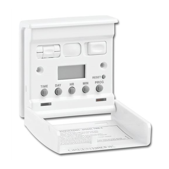
ELECTRONIC WALL
SWITCH TIMER
INSTALLATION/OPERATING
INSTRUCTIONS
M M O O D D E E L L N N U U M M B B E E R R : : T T 4 4 0 0 S S - - C C
H
A
L
J
B
G
C
F
D
K
E
A.FUSE CARRIER Pull out to replace
fuse (a special 2A BS646 20mm x
5mm, this is not an ordinary fuse)
B.LCD DISPLAY
C. to G BUTTONS TO SET DAY, TIME
AND PROGRAMME AND RANDOM
H.PUSH ON/OFF SWITCH ALLOWS
UNIT TO OPERATE AS ORDINARY
LIGHT SWITCH ACTIVATES EVEN
WHEN LID IS SHUT.
L. OVERRIDE SWITCH
MAN = MANUAL MODE
AUTO = AUTOMATIC PROGRAMME
MODE
J. RESET BUTTON
K.RED NEON FUNCTION
I I F F I I N N D D O O U U B B T T , , I I N N S S T T A A L L L L A A T T I I O O N N
S S H H O O U U L L D D B B E E M M A A D D E E B B Y Y A A Q Q U U A A L L I I F F I I E E D D
E E L L E E C C T T R R I I C C I I A A N N I I N N A A C C C C O O R R D D A A N N C C E E W W I I T T H H
C C U U R R R R E E N N T T W W I I R R I I N N G G R R E E G G U U L L A A T T I I O O N N S S
WIRING INSTRUCTIONS
Before attempting any installation work
turn off the electrical supply at the mains
switch, fuse box or consumer unit and
for additional safety remove the fuse.
GreenBrook security wall light switches
cannot be used with other electronic
products.
1. After installation, the internal back up
battery will need to be fully charged to
enable correct operation.
2.After the main supply is switched back
on, wait 5 minutes and operate the
reset button and allow the internal
battery to charge for 45-60 minutes.
After this period follow the operating
instructions as normal.
3.DO NOT use in two-way systems with
dimmers or any other switch
containing electronic circuitry.
4.Suitable for tungsten filament bulbs
40W to 400W maximum and most low
energy
(CFL) 11W and above. Not
suitable for low voltage lighting.
5.Not suitable in 3-way circuits.
N N O O T T E E
If using a metal backbox this should be
earthed.
WIRING INSTALLATION IN ONE
WAY SWITCHED CIRCUIT
Diagram 1- Before
Diagram 2 - After
YELLOW & GREEN EARTHS MUST REMAIN
CONNECTED TO METAL BACK BOX
WIRING INSTALLATION IN TWO
WAY SWITCHED CIRCUIT
Before installing your Security Wall Light
Switch in a two way circuit, it is first
necessary to determine which method of
wiring has been used in your home.
The primary reason for doing this is to
make sure that the switch is wired in
such a way that has a permanent live
feed at all times in order to power the
electronic timer.
1. TURN OFF THE MAIN SUPPLY
2.Loosen the two switch plates from
the wall.
3.Do NOT disconnect any wires at this
stage.
4.Study the existing wiring arrangement;
compare to the 'before' illustrations.
-If you find 3 wires at each switch
(excluding the earth wire) see Diagram
3.-If you find 5 wires at one switch and
5 wires at the other (excluding the
earth wire) see Diagram 5.
After establishing the appropriate
wiring method, install the security light
switch as per the corresponding 'after'
illustration.
Advertisement
Table of Contents

Related Manuals for GreenBrook T40S-C


Summary of Contents for GreenBrook T40S-C
- Page 1 4.Study the existing wiring arrangement; 1. If the digital display remains blank, GreenBrook security wall light switches compare to the ‘before’ illustrations. press the RESET button. Also, check cannot be used with other electronic that the light bulb has not blown.
- Page 2 Diagram 3 - Before STEP 5 STEP 7 SETTING PRESENT Press PROG button G so that the Press HR and MIN buttons E and F to DAY & TIME set required off time: first OFF time can be entered: To access controls, with thumb and SA SU forefinger on either side, ease cover MO TU WE TH FR SA SU...
Need help?
Do you have a question about the T40S-C and is the answer not in the manual?
Questions and answers