GreenBrook T612-C, T634-C - Central Heating Programmer Manual
- Installation & operating instructions (2 pages) ,
- Simplified programming instructions (3 pages)
Advertisement
Introduction
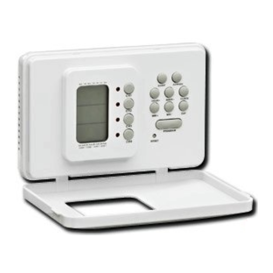
The T634-C/T612-C programmer offers the equivalent of four or two separate seven day timers in one slim, elegant enclosure. Each of the four or two channels offers up to three programmed operating periods per day for each of the seven days of the week, with a boost and advance available on each.
INSTALLATION AND CONNECTION SHOULD ONLY BE CARRIED OUT BY A SUITABLY QUALIFIED PERSON AND IN ACCORDANCE WITH THE CURRENT EDITION OF THE IEE WIRING REGULATIONS.

ISOLATE MAINS SUPPLY BEFORE COMMENCING INSTALLATION
INSTALLATION INSTRUCTIONS
FITTING THE MOUNTING PLATE
The mounting plate should be carefully removed from the timer by loosening the two securing screws on the top of the timer and swinging out the mounting plate away from the body of the timer. The mounting plate should be fitted with the wiring terminals located at the bottom and in a position which allows the required clearances around the mounting plate to allow re-fitting of the timer body.

WIRING BOX MOUNTING
The Mounting plate may be fitted directly on to a single gang steel flush wiring box complying with BS4662, using two 3.5mm screws. The T634-C/T612-C programmer is suitable for mounting on a flat surface only; it must not be located on a surface mounted box or on unearthed metal surfaces.
ELECTRICAL CONNECTIONS
All necessary electrical connections should now be made. Flush wiring can enter from the rear through the aperture in the mounting plate. The mains supply terminals are intended to be connected to the supply by means of fixed wiring.
The recommended cable sizes are 1.0mm2 or 2.5mm2.
The T634-C/T612-C programmer is double insulated and does not require an Earth connection but an Earth terminal is provided on the mounting plate for terminating any cable Earth conductors. Earth continuity must be maintained and all bare Earth conductors must be sleeved with green/yellow sleeving. Ensure that no conductors are left protruding outside the central space encompassed by the mounting plate, and there are no strands of loose conductors protruding from the terminals.
INTERNAL WIRING DIAGRAM FOR T634-C and T612-C

An example circuit diagram is shown above. This diagram is schematic and should be used as a guide only. Please ensure that all installations comply with the current IEE regulations.
FITTING THE PROGRAMMER
Make sure the two captive screws on the top of the mounting plate are loose. Locate the two lugs on the lower edge of the mounting plate into the two corresponding apertures on the timer. Swing the top of the timer into position, ensuring that the connection pins on the rear of the unit locate into the terminal slots on the mounting plate. Tighten the two captive retaining screws.
OPERATING INSTRUCTIONS
This is a four/or two channel programmable timer. It is used for controlling home appliances such as heaters, lighting systems and so on. This timer has 4 or 2 individual channels. Each channel works in automatic or manual operating mode.
LCD Display Layout

TIME FUNCTION
- 12hr and 24hr display format selection by pressing CLOCK and HOUR+.
The default is 24hr format. - Day, hour, minute are shown on the LCD.
- Clock setting
Press CLOCK and then press DAY to set the day of the week. Press HOUR+ and Hour to set the hour of the day. Press HOUR+ or Hour- and hold for 2 secs and the hour digits will be changed continuously. Press MIN+ or Min- to set the minute of the clock. Press MIN+ or MIN- and hold for two seconds, the minute digits will be changed continuously.
AUTO MODE
- There are three groups of programs in each channel.
- The start and end time must be both set. Otherwise the timer will ignore the settings that have been entered.
- Program setting
Take Channel 1 ( CH1 ) as an example:-
Press PROG and CH1 simultaneously, the AUTO and ON icons of channel 1 will light up. The LCD display will show 1 START - -: - -. Press DAY to select the following combinations:-- Mon to Sun
- Mon to Fri
- Sat and Sun
- Any day in a week
Press Hour+ or Hour- to set the hour digits. Press the key for 2 seconds and the hour digits will change continuously. Press MIN+ or MIN- to set minute digits. Press the key for 2 seconds and the minutes digits will change continuously. Press PROG to confirm START time and enter to set END time of channel 1 (CH1).
The AUTO and OFF icons of channel 1 will light up. The LCD will display 1 END - -: - -. The setting procedure is the same as the START time above. Press PROG to confirm the END time of the first program. It automatically goes into the setting of the START time of the second program. This procedure repeats until the END time of the third program has been set. Press Clock to go back to the normal LCD display.
- Program review
Take Channel 1 (CH1) as an example. Press Clock and CH1 at the same time. The START time and END time of each program will be displayed for 2/3 seconds one by one automatically. After completion, the display will return back to the normal LCD display. If, there is no time setting in a program. The screen will display - START - -: — or + END - -: - - respectively. - The program setting procedure is the same for all the channels.
BOOST FUNCTION
Take CH1 as an example.
- Press BOOST and CH1 simultaneously to enable BOOST function. Channel 1 loading is activated and channel 1 LED turns on. After one hour, channel 1 loading will be deactivated automatically.
- Press BOOST and CH1 again to cancel BOOST mode.
- In BOOST mode, icon B on the LCD screen turns on. Icon B on LCD will be off while BOOST function is disabled. NOTE: BOOST can be enabled in manual mode and auto mode. This procedure applies to every channel. ADVANCE and BOOST do not work at the same time.
ADVANCE FUNCTION
Take CH1 as an example.
- Press ADVANCE and CH1 simultaneously to enable ADVANCE function. Channel 1 LED will turn on. Icon A on the LCD screen will turn on. The ADVANCE function will finish at the end time of the current program and the 'A' icon will turn off.
- Press ADVANCE and CH1 again to disable ADVANCE function. Icon A on the screen will be off while ADVANCE function is disabled.
NOTE: ADVANCE will only work when in auto mode. ADVANCE and BOOST do not work at the same time.
MANUAL MODE
Take CH1 as an example.
- Press CH1. The wording CH1 will be shown on the LCD display and the 'CH1 ON' icon will turn on. The loading of CH1 will be activated. The auto mode of CH1 is manually overridden by your set program.
- Press CH1 again, the wording CH1 will still be shown on the LCD display. The CH1 OFF icon turns on and CH1 ON icon turns off. The loading of CH1 will be deactivated. The auto mode of CH1 is manually overridden.
- Press CH1 again, the wording CH1 will be still shown on LCD display. The CH1 Auto icon turns on and CH1 OFF icon turns off. The unit is now working in AUTO mode. The loading of CH1 will be activated according to the user defined program.
- Press CH1 continuously and repeat steps 1 to 3. This procedure applies to every channel.
NORMAL LCD DISPLAY
Suppose all the channels are activated and all the channel LED's are on, CH1 is the default display even if the timer is in manual or auto mode.
RESET FUNCTION
Press RESET to erase all time settings. All the segments on LCD will turn on then the LCD screen will go back to the normal LCD display. All the channels will work in AUTO mode. The AUTO icon of each channel will turn on. Monday is selected.
AUTOMATIC RETURN FUNCTION
The LCD screen display will return to normal 60secs after the last button was pressed.
SUMMER TIME FUNCTION
To change the time so it is one hour ahead simply press DAY and MIN+ once and one hour will be added to the current time. Press DAY and MIN+ to cancel this function.
BACKLIGHT FUNCTION
The backlight is set to stay on for 10 seconds after a button is pressed.
MEMORY KEPT BY BACKUP BATTERY
When the power to the timer is lost (i.e. there is a power cut), the built-in battery back up will ensure the timer stays on. The battery back up can last up to 7 days.
TECHNICAL INFORMATION
| Display: | LCD | |
| Working Voltage: | 230V-50Hz | |
| Max Load of Single Channel: | Resistive - Inductive - | 3A, 690W 1.25A, 230W at 0.8 power factor |
| Working Condition: | Indoor use only | |
WEST ROAD. HARLOW
ESSEX. CM20 2BG. UK
sales@greenbrook.co.uk
WWW.GREENBROOK.CO.UK

Documents / Resources
References

Download manual
Here you can download full pdf version of manual, it may contain additional safety instructions, warranty information, FCC rules, etc.
Download GreenBrook T612-C, T634-C - Central Heating Programmer Manual
Advertisement


Need help?
Do you have a question about the T612-C and is the answer not in the manual?
Questions and answers