
Related Manuals for LG V-C3850ND


Summary of Contents for LG V-C3850ND
-
Page 1: Vacuum Cleaner
VACUUM CLEANER SERVICE MANUAL CAUTION BEFORE SERVICING THE UNIT, READ THE "SAFETY PRECAUTIONS" IN THIS MANUAL. MODEL : V-C3850ND/NT/NDV/NTV/RD/RT/RDV/RTV V-C3852ND/NT/NDV/NTV/RD/RT/RDV/RTV V-C3854RTV V-C3860RD/RT/RDV/RTV... -
Page 2: Table Of Contents
CONTENTS SAFETY PRECAUTIONS......................3 SERVICING PRECAUTIONS ......................4 SPECIFICATIONS......................... 4 FEATURES............................ 4 DESCRIPTION..........................5 CONTROL PANEL ........................5 VACUUM POWER ADJUSTMENT....................5 DISASSEMBLY INSTRUCTIONS....................6~7 TROUBLESHOOTING GUIDE ....................8~10 BLOCK DIAGRAM ........................ 11~12 SCHEMATIC DIAGRAM......................11~12 PRINTED CIRCUIT BOARD ....................11~12 EXPLODED VIEW ....................... -
Page 3: Safety Precautions
SAFETY PRECAUTIONS BEFORE OPERATING THIS VACUUM CLEANER, READ THIS SERVICE MANUAL THOROUGHLY, AND OBSERVE EACH POINT CAREFULLY. 1. Change the paper bag or clean the cloth 5. Attachments bag in case the indicator moves toward red. • Nozzle : For cleaning wooden floor, the room floor and carpet. -
Page 4: Servicing Precautions
(V-C3850RD/RT/RDV/RTV) (V-C3854RTV) NOZZLE ASS’Y ............1EA (V-C3860RD/RT/RDV/RTV) ON/OFF ON BODY CREVICE TOOL (ON BOARD) ........1EA (V-C3850ND/NT/NDV/NTV) DUST BRUSH (ON BOARD)........1EA (V-C3852ND/NT/NDV/NTV) CLOTH BAG ASS’Y (OPTION) ........1EA -SUB : VACUUM POWER ADJUSTMENT BY SLIDE KNOB EXTRA PAPER BAG ASS’Y (PAPER, OPTION) ..1EA •... -
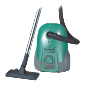
Page 5: Description
CONTROL LOCATION Flexible Hose Ass’y Control Button (ON/OFF) Telescopic Tube (Rotary) Handle & Metal or Plastic Cord Reel Button Tube Power Cord Dust Indicator Flexible Hose Ass’y Nozzle Hose Head Hose Button Body Cover Pedal Suction Hole Wheel Cover Latch Pedal Nozzle Filter Cover... -
Page 6: Disassembly Instructions
DISASSEMBLY INSTRUCTIONS NOTE: Before attempting to service or adjust any part of the vacuum cleaner, disconnect the electrical power supply cord from the wall outlet. 2. Body Cover Assembly Replacement • Almost all of the parts of this vacuum cleaner can be disassembled with a screw driver and each connecting 1) Remove the four screws fastening the body base. - Page 7 3. P.W.B Assembly Replacement 4) When reassembling, assemble control button after rotating the switch of P.W.B assembly in the direction of the arrow. 1) Remove a screw fastening “Support Board” on body cover Switch Button Spring Control Button Body Cover Support Board 4.
-
Page 8: Troubleshooting Guide
TROUBLE SHOOTING GUIDE 1. SWITCH ON BUT MOTOR DOSE NOT RUN. CHECKING CAUSE SOLUTION Abnormal The fuse is melt down Exchange the fuse Check the power source in the coverknife switch Poor plug insertion Insert again Power cord cut Repair or exchange Interior lead wire cut Exchange the lead wire Normal... - Page 9 3. SWITCH OFF BUT MOTOR RUNS. Poor connection Repair Poor switch Exchange the switch 4. WEAK SUCTION POWER Exchange the carbon brush Carbon brush defaced or the motor Motor armature cut Exchange the motor Low rotation speed Foreign matters attached to Remove the foreign matters the impeller Inquire to the power utility...
- Page 10 5. VIBRATION NOISES Loose parts Secure firmly Unbalanced motor assembly Exchange or repair the motor Foreign matters are attached Remove the foreign matters to the impeller Exchange the carbon brush Poor carbon brush rectification or the motor Armature is cut or foreign Exchange motor matters attached Remove foreign matters...
-
Page 11: Block Diagram
V-C3850ND/NT/NDV/NTV BLOCK DIAGRAM V-C3852ND/NT/NDV/NTV CORD REEL MOTOR ASS'Y PLUG BR:BROWN BL:BLUE SCHEMATIC DIAGRAM PLUG BR:BROWN BL:BLUE CIRCUIT DIAGRAM 0.47 250V -11-... -
Page 12: Block Diagram
V-C3850RD/RT/RDV/RTV V-C3854RTV BLOCK DIAGRAM V-C3852RD/RT/RDV/RTV V-C3860RD/RT/RDV/RTV CORD REEL MOTOR ASS'Y PLUG BR:BROWN BL:BLUE SCHEMATIC DIAGRAM PLUG BR:BROWN BL:BLUE CIRCUIT DIAGRAM SLIDE VOLUME 1/2W 0.47uF TRIAC 250V 3.9K DIAC 0.1uF 1/2W 250V 1/2W 1/2W -12-... -
Page 13: Exploded View
EXPLODED VIEW BASE ASSEMBLY, BODY 146811 139201 139202 152302 139204 152301 146871 152312 650581 152311 652031 149601 130401 144411 146601 -13-... - Page 14 EXPLODED VIEW COVER ASSEMBLY, BODY 236501 252311 235502 235501 250204 250204 249701 249701 168711 168711 349801 349801 335501 340261 343501 335211 339201 -14-...
- Page 15 HOSE ASSEMBLY, FLEXIBLE 452151 449401 449401 452001 452001 435501 435501 TYPE 1 TYPE 2 NOZZLE ASSEMBLY 552493 552491 NZ-10 NZ-12 NZ-15 NZ-16 NZ-17 NZ-5 NZ-4 -15-...
- Page 16 EXPLODED VIEW ACCESSORIES 650631 652011 652012 652481 -16-...
-
Page 17: Replacement Parts List
REPLACEMENT PARTS LIST LOCATION No. PART No. DESCRIPTION REMARK 139201 3920FI4718M PACKING, DUST SEAL 149601 4960FI2322A 149601 MOUNT, BAG 149601 130401 3040FI1490A SHADOW GRAY 130401 BOSE, BODY 130401 FILTER(MECH) 152301 4I70098K POLYESTER MOTOR SAFETY 144411 4441FI3605C CASTER ASS’Y BLACK 144411 144411 146601 4660fi2412A... - Page 18 REPLACEMENT PARTS LIST LOCATION No. PART No. DESCRIPTION REMARK 252311 5231FI3772A FILTER ASS’Y, EXHAUSTER 252311 5231FI3772A 349801 4980FI2425 BOARD, SUPPORT Rotary, Refer To Appendix 349801 4980FI2426 BOARD, SUPPORT ON/OFF, Refer To Appendix 168711 6871FX2148 PWB(PCB) ASS’Y Rotary, Refer To Appendix 168711 6871FX2148 PWB(PCB) ASS’Y...
-
Page 19: Appendix
APPENDIX 1. THE TYPE OF POWER CORD & PARTS NUMBER CORD REEL ASS’Y P/NO TYPE TYPE OF PLUG APPLICATION (L/NO.:146871) 12.7 Color identification of fuse Brown Yellow Blue -19-... -
Page 20: Color & Parts Number
2. COLOR & PARTS NUMBER COLOR BASF SHADOW LOCATION BLUE GRAY DESCRIPTION 335501 COVER, FILTER 3550FI1378A 340261 LATCH 4026FI3671A 24350 RING, CONNECTOR 4350FI3776A 236501 HANDLE 3650FI1490A 235501 COVER, BODY 3550FI1579A 235502 COVER, REAR 3550FI1580A 250204 BUTTON, CONTROL (for Rotary) 5020FI3774A 250204 BUTTON, CONTROL (for ON/OFF) 5020FI3777A... -
Page 21: Motor & P.w.b Ass'y & Cord Reel Ass'y Parts Number
3. MOTOR & P.W.B ASS’Y & CORD REEL ASS’Y PARTS NUMBER L/NO. P/NO DESCRIPTION REMARK 146811 4681FI2456A MOTOR ASS’Y, VC VMC-460E5, 230 / 220V / 50Hz 146811 4681FI2457A MOTOR ASS’Y, VC VMC-420E5, 230 / 220V / 50Hz 146871 4687FI1472J CORD REEL ASS’Y C-2, 6.8m 168711 6871FX2148A... - Page 22 MEMO -22-...
- Page 23 MEMO -23-...
- Page 24 Aug. 2001 P/No. : 3828Fi5865A printed in Korea...
Need help?
Do you have a question about the V-C3850ND and is the answer not in the manual?
Questions and answers