Table of Contents
Advertisement
Advertisement
Table of Contents

Related Manuals for Fire Chief 500


Summary of Contents for Fire Chief 500
- Page 1 Wood and Coal Burning Furnace Model 500, 700 and 1100 “E” Series Owner’s Manual M A D E M A D E M A D E M A D E M A D E U S A U S A...
- Page 2 USA. Please take a few moments to carefully read the owner’s manual. By taking the time to familiarize yourself with your new Fire Chief, you will be able to look forward to years of trouble-free, dependable service.
-
Page 3: Table Of Contents
Table of Contents Specification/Location ..............4 Furnace Components Placement ........... 5 Ducting/Fuel Requirements ............5 Location and Installation ............. 6 Chimney Recommendations ............7 Initial Firing/General Operations ..........8 Ash Removal ................8 General Operation ..............9 Creosote Prevention Tips ............. 9 Chimney Fire Warning .............. -
Page 4: Specification/Location
FORCED HOT AIR CIRCULATION: The plenum size of your Fire Chief must not be reduced to less than 12" (twelve inches) round or 79 square inches and must provide a minimum of eighteen inches between the top of your Fire Chief and the main trunk connection. -
Page 5: Furnace Components Placement
400 feet to 600 feet per minute at the registers. The heat outlet area should never be less than 12 sq. in. round. The Fire Chief MUST be installed with a cold air return system. The system should be a minimum of 10% larger than the heat outlet to readily transfer the cold air back to the furnace. -
Page 6: Location And Installation
Regardless of your choice of flue type, for Models 500 and 700, a minimum 6” diameter and for the Model 1100, a minimum of 8" diameter . In order to create the most efficient draft, the chimney size should not exceed 12 inches with a minimum of .08 inches water... -
Page 7: Chimney Recommendations
Chimney Recommendations The termination cap should be designed to inhibit down- drafting without restricting Chimney experts have determined that the the exhaust discharge. chimney termination should be at least 2' above the highest portion of the roof that is within a 10' radius of the chimney. -
Page 8: Initial Firing/General Operations
SEE PAGE 10 NOTE: Your new Fire Chief is capable of producing a very high output of Btu’s. Do not fuel your furnace to capacity upon initial firing. Instead, we recommend becoming thor- oughly familiar with your Fire Chief Furnace before operating at full capacity. -
Page 9: General Operation
2. Remove the ashes from your Fire Chief Furnace at least once a day - or as often as necessary to ensure the ashes do not accumulate to the height of the grates. If ash build-up occurs at grate level, it will cause premature failure of the grates, voiding the warranty on the grates. -
Page 10: Blower And Filter Box Assembly Instructions
If your inspection reveals a discrepancy, contact your Dealer or call 800.875.4788 for help. NOTE: for your convenience your Fire Chief has been factory assembled and the elec- tric wiring harness is pre-wired. -
Page 11: Wiring Diagram
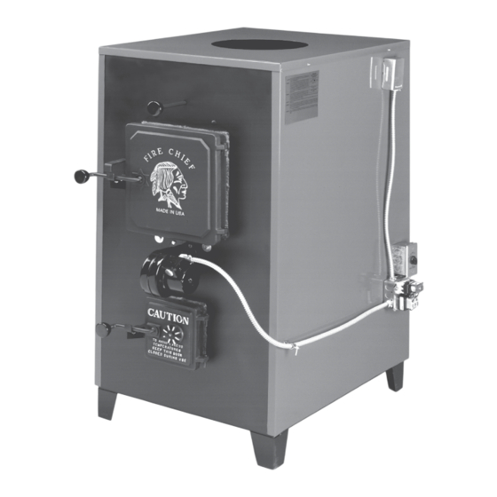
FC500E/FC700E/FC1100E... - Page 12 FIRE CHIEF FURNACE Model FC500E, FC700E and FC1100E Refer to Assembly Instructions on Page 11 This drawing shows the furnace with the electrical system and filter box properly installed. The bracket must be attached to the side of the furnace to secure the conduit.
-
Page 13: Draft Blower Operation
FRONT DRAFT BLOWER: he front draft blower plays an important role in your Fire Chief furnace’s operation. When the wall thermostat calls for heat, the draft motor turns on and supplies fresh air into the firebox producing a hotter fire which in turns provides more heat in the heat chamber. -
Page 14: Parts Diagram
Models 500E,700E,1100E Parts Diagram For Grates: Refer to page 17 Grates listed by Model Insulation: Not Shown Insulation for Furnace Sides, All Models - FCIN - 2 per Furnace... -
Page 15: Parts List
FIRE CHIEF 500E, 700E AND 1100E PARTS LIST ITEM # DESCRIPTION QUANTITY Hex Bolt - 5/16-18 X 2 3/4” Rear Cast Plate - FCRCP Hex Lock Nut, 5/16-18 Flat Washer, 9/16 ID Roller Grate Retainer - FCMR - Refer to page 17... -
Page 16: Furnace Parts Sold As Kits
FIRE CHIEF PARTS LIST, continued Furnace Parts Sold as Kits: For Models/Series as Listed FC500E; FC700E AND FC1100E Series only - 2009 and Newer Production Electrical Control Center: Wall Thermostat, Draft Blower, Rocker Switch, 3-Speed Blower Switch, Fan Limit Control, Fan Relay Center and 3’ Cord for each Model. -
Page 17: Grates With Diagram By Model
FIRE CHIEF GRATES, BY MODEL Grates By Model: Refer to Complete Diagram on Page 15 - Diagrams are for Grates only and quantity needed for each model. Model 500 Grates - Rear Grate, L - FC5RG ......1 Front Roller Grate, F - FCFG ....1 Roller Grate Handle, - FCSGH .... -
Page 18: Optional Equipment: Back Draft Damper And Hot Water Coil
Fire Chief as practical. Press the female end of the damper over the Fire Chief Furnace collar or male end of the duct pipe. When properly positioned, the arrows on the air flow decal point "away"... -
Page 19: Troubleshooting Guide
TROUBLESHOOTING SUGGESTED REMEDY PROBABLE CAUSE PROBLEM • Wood has rotted or has Inspect the wood for obvi- 1. Bugs found in wood. ous signs of insect infesta- been laying around for an ex- tion such as burrows or tended period of time. holes and avoid using if pos- sible. - Page 20 TROUBLESHOOTING PROBABLE CAUSE PROBLEM SUGGESTED REMEDY • Defective fan limit con- Check by moving "ON" posi- 4. Circulation blower will trol. tion indicator to temperature not turn on. position where the blower should turn on. If the blower fails to run, replace the fan limit.
- Page 21 TROUBLESHOOTING PROBLEM PROBABLE CAUSE SUGGESTED REMEDY 6. Circulation blower vi- located. an acceptable balance. If you brates , continued. are unsuccessful, contact your supplier. • Defective main bearings Return the blower to your supplier for replacement. 7. Odor detected in home •...
-
Page 22: Warranty Information
TROUBLESHOOTING PROBLEM PROBABLE CAUSE SUGGESTED REMEDY 9. Down draft on chim- Replace or re-line chimney. symptom may occur in fac- ney, continued. tory built flues because the insulation has settled or a seam has ruptured. In ma- sonry flues, mortar loss may be causing the aspiration of cooler outside air into the stack. - Page 23 TROUBLESHOOTING PROBLEM PROBABLE CAUSE SUGGESTED REMEDY Always open the door cau- 11. Flames discharging from • Opening the door has tiously and allow the safety fuel door during reloading. provided additional oxygen latch system to perform its which has ignited accumu- designed function of contain- lated gases from partially ing ignite gases within the fire...
- Page 24 TROUBLESHOOTING SUGGESTED REMEDY PROBLEM PROBABLE CAUSE Home does not airtight. We recommend in- not receiving an adequate stalling an aperture to the achieve comfortable tem- amount of oxygen. perature, continued outside consisting of a mini- mum of twelve square inches or 4” round. Provide additional insulation.
- Page 25 TROUBLESHOOTING PROBABLE CAUSE SUGGESTED REMEDY PROBLEM • Insufficient chimney SEE #9 14. Rapid accumulation of draft. creosote, continued. • Using Un-insulated stove DANGER: Never use un-in- pipe for the chimney, espe- sulated stove pipe as chim- cially if the construction is on ney.
- Page 26 For your convenience, you may wish to record the following information: Fire Chief Model Number: ______________________________________ Serial Number: ______________________________________________ Purchase Date: _____________________________________________ Dealer Where Purchased: _______________________________________ Additional Service Information: __________________________________ _ _ _ _ _ _ _ _ _ _ _ _ _ _ _ _ _ _ _ _ _ _ _ _ _ _ _ _ _ _ _ _ _ _ _ _ _ _ _ _ _ _ _ _ _ _ _ _ _ _ _ _ _ _ _ _ _ _ _ _ _ _ _ _ _ _ _ _ _ _ _ _ _ _ _ _ _ _ _ _ _ _ _ _ _ _ _ _ _ _ _ _ _ _ _ _ _ _...
- Page 27 Fire Chief Furnace so long as the furnace may be operated safely in accordance with the owner’s manual. Cast iron grates and air baffle are not covered by warranty for burn through caused by the accumulation of ash build-up.
Need help?
Do you have a question about the 500 and is the answer not in the manual?
Questions and answers