Table of Contents
Advertisement
Available languages
Available languages
Owner's Manual
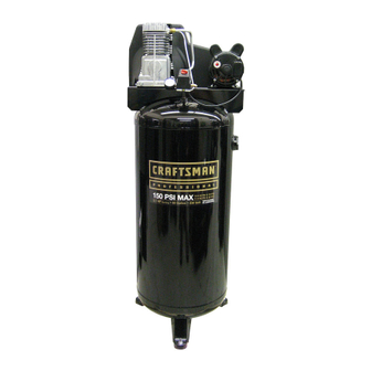
AIR COMPRESSOR
Oil Lubricated
Single Stage
Belt Drive, Electric
60 Gallon Vertical
Model No. 921.16476
CAUTION:
Before using this product,
read this manual and follow
all its Safety Rules and
Operating Instructions.
Sears Brands Management Corporation, Hoffman Estates, IL 60179 U.S.A.
www.craftsman.com
5/7/2010
Part No. 200-2794
•
Safety Instructions
•
Installation & Operation
•
Maintenance & Storage
•
Troubleshooting Guide
•
Parts List
•
Español, p. 18
•
Français, p. 29
Advertisement
Chapters
Table of Contents

Related Manuals for Craftsman 921.16476


Summary of Contents for Craftsman 921.16476
-
Page 1: Air Compressor
Owner’s Manual AIR COMPRESSOR Oil Lubricated Single Stage Belt Drive, Electric 60 Gallon Vertical Model No. 921.16476 CAUTION: • Safety Instructions Before using this product, • Installation & Operation read this manual and follow • Maintenance & Storage all its Safety Rules and •... -
Page 2: Table Of Contents
Sears Brands Management Corporation, Hoffman Estates, IL 60179 U.S.A. SPECIFICATION CHART APPROXIMATE APPROXIMATE RUNNING TANK CAPACITY VOLTAGE/ CUT-IN CUT-OUT MODEL NO. H.P. GALLONS AMPS/PHASE PRESSURE PRESSURE 921.16476 Vert. 60 (228 Liters) 230/15/1 (WLB3106016) (8,27 bar) (10,34 bar) 200-2794... -
Page 3: Safety Guidelines
SAFETY GUIDELINES The following information relates to protecting YOUR SAFETY and PREVENTING EQUIPMENT PROBLEMS. To help you recognize this information, we use the following symbols. Please read the manual and pay attention to these sections. DANGER: – A POTENTIAL HAZARD THAT WILL CAUSE SERIOUS INJURY OR LOSS OF LIFE. WARNING: –... -
Page 4: Glossary Of Terms
IMPORTANT SAFETY INSTRUCTIONS WARNING: RISK OF FIRE. Unattended operation of this compressor could result in personal injury or property damage. To reduce the risk of fire, do not allow the compressor to operate unattended. Always disconnect electrical power by turning the pressure switch to off and drain the tank daily or after each use. RISK TO BREATHING. -
Page 5: Overview
OVERVIEW BASIC AIR COMPRESSOR COMPONENTS The basic components of the air compressor are the electric motor, pump, pressure switch and tank (see Fig. 1). The electric motor (see A) powers the pump. The electric motor is equipped with an overload protector to help prevent possible motor burnout. -
Page 6: Typical Installation
TYPICAL INSTALLATION WARNING: Risk of bursting, resulting in injury. Never use plastic pipe for compressed air. CAUTION: Never use lubricator for paint spraying or similar applications. moisture trap and drain. Air/water filters should also be installed Air flow in the positions shown. Feeder line Drain leg Air pressure regulation... -
Page 7: Compressor Controls
COMPRESSOR CONTROLS Main Power Disconnect If the pressure switch does not shut off the compressor at it’s Install a main power disconnect switch in the power line to “cut-out” pressure setting, the safety valve will protect against the compressor, near the compressor’s location. It is operated high pressure by releasing tank pressure at it’s factory set manually, but when it is in the ON position, the compressor will pressure (slightly higher than the pressure switch “cut-out”... -
Page 8: Operating Instructions
OPERATING INSTRUCTIONS the tank. BREAK-IN OF THE PUMP Make sure the power is connected at the power panel. Check the oil level in the pump (see “Checking the Oil” in the maintenance section). Open the petcock (see C). CAUTION: Escaping air and moisture can propel debris that may cause eye injury. -
Page 9: Maintenance
MAINTENANCE use. Do not use the unit with the shrouds or belt MAINTENANCE guard removed. Serious injury could occur from WARNING: contact with moving parts. To avoid personal injury, always shut off and unplug the compressor and relieve all air pressure Proper belt tension and pulley alignment must be maintained from the system before performing any service on the air for maximum drive efficiency and belt life. - Page 10 MAINTENANCE NOTE: Once the motor pulley has been moved from its factory Shift the motor towards the pump to the point where the belt set location, the grooves of the flywheel and pulley must can be easily removed and installed. be aligned to within 1/16”...
-
Page 11: Service Interval
MAINTENANCE CLEANING THE AIR FILTER A dirty air filter will reduce the compressor’s performance and life. To avoid any internal contamination of the pump, the filter should be cleaned frequently, and replaced on a regular basis. Felt filters should be cleaned in warm, soapy water, rinsed, and allowed to air dry before reinstallation. -
Page 12: Troubleshooting Chart
TROUBLESHOOTING Note: Troubleshooting problems may have similar causes and solutions. PROBLEM POSSIBLE CAUSE SOLUTION Excessive current draw Low voltage/motor overload Check that power supply is adequate and that compressor is on a trips circuit breaker or dedicated circuit. motor reset switch Drive belt too tight Readjust belt tension. -
Page 13: Parts Drawings And Parts Lists
PARTS DRAWING / ESQUEMA DE LAS PIEZAS / DESSIN DES PIÈCES PARTS LIST / LISTA DE PIEZAS / LISTE DE PIÈCES Item Part No. Artículo Nº de pieza Cant. Article No / P Qté Description Descripción Description Switch, pressure (includes items Interruptor (incluye los artículos Interrupteur (inclut les éléments 034-0228... - Page 14 PARTS DRAWING / ESQUEMA DE LAS PIEZAS / DESSIN DES PIÈCES 200-2794...
- Page 15 PARTS LIST / LISTA DE PIEZAS / LISTE DE PIÈCES Item Part No. Artículo Nº de pieza Cant. Article No / P Qté Description Descripción Description 125-0151 Belt guard, outer Protector Garant Screw, #10-14 Tornillo 146-0016 Chaveta Clé 007-0037 V-Belt, 4L-530 Correa Courroie 006-0142...
- Page 16 PARTS DRAWING / ESQUEMA DE LAS PIEZAS / DESSIN DES PIÈCES 165 Pump Assy Sequence #’s 1, 2, 3, 4, 5, 6, 7 & 8 Pump Specifications Head Bolt Torque Sequence Torque to 220–300 lbs-in Weight–39 lbs. Secuencia de apriete de los Oil Capacity (approx.)–18 oz.
- Page 17 PARTS LIST / LISTA DE PIEZAS / LISTE DE PIÈCES 165 Pump Assy Item Part No. Description Descripción Description Artículo Núm / P Cant Article No / P Qté 059-0144 Screw, 5/16–18 x 2.50” lg Tornillo 054-0112 Ring set Juego de anillos Jeu d’anneaux 048-0065 Piston assembly...
- Page 18 Sears Brands Management Corporation, Hoffman Estates, IL 60179 EE. UU. CUADRO DE ESPECIFICACIONES RUNNING PRESIÓN DE PRESIÓN DE H.P. CAPACIDAD DEL VOLTAJE ENCENDIDO APAGADO MODELO (CV) DEPÓSITO - LITROS AMP/FASE (APROXIMADA) (APROXIMADA) 921.16476 Vert. 228 Litros 230/15/1 (WLB3106016) (8,27 bar) (10,34 bar) 200-2794...
-
Page 19: Pautas De Seguridad
PAUTAS DE SEGURIDAD La información que sigue se refiere a la protección de SU SEGURIDAD y la PREVENCIÓN DE PROBLEMAS DEL EQUIPO. Como ayuda para reconocer esta información, usamos los siguientes símbolos. Lea por favor el manual y preste atención a estas secciones. PELIGRO: - RIESGO POTENCIAL DE LESIONES GRAVES O LA PÉRDIDA DE LA VIDA. -
Page 20: Glosario De Términos
INSTRUCCIONES DE SEGURIDAD IMPORTANTES ADVERTENCIA: RIESGO DE •Nunca intente, por ningún motivo, ajustar la válvula de seguridad del depósito. Hacerlo anulará la garantía. La EXPLOSIÓN. válvula de seguridad ha sido preconfigurada en fábrica a la presión máxima que soporta esta unidad. Si se manipula la válvula de seguridad, existe el riesgo de que se produzcan lesiones personales o daños materiales. -
Page 21: Resumen General
RESUMEN GENERAL bomba vuelve a comprimir el aire. COMPONENTES BÁSICOS DEL COMPRESOR DE AIRE Los componentes básicos del compresor de aire son el motor eléctrico, la bomba, el interruptor de presión y el depósito (Fig. 1). El motor eléctrico (vea A) acciona la bomba. El motor eléctrico está... -
Page 22: Instalación Típica
INSTALACIÓN TÍPICA ADVERTENCIA: Existe el riesgo de lesiones por quemaduras. Nunca use tubería de plástico para aire comprimido. PRECAUCIÓN: Nunca use lubricador para rociar pintura o aplicaciones similares. Flujo del aire herramienta. Para eliminar esta humedad, dirija la línea principal Línea de alimentación de aire hacia un colector de humedad y proceda a a su vaciado. -
Page 23: Controles Del Compresor
CONTROLES DEL COMPRESOR Interruptor principal de alimentación alcanza el nivel establecido de "presión de apagado", la válvula Instale un interruptor principal de desconexión en la línea de de seguridad protegerá el depósito aliviando la presión del mismo alimentación hacia el compresor, cerca de la ubicación de éste. cuando se sobrepase la presión máxima establecida en fábrica Este interruptor apaga el compresor. -
Page 24: Requisitos De Alimentación Eléctrica
REQUISITOS DE ALIMENTACIÓN ELÉCTRICA número) a fin de sobreponerse a la pérdida de voltaje inherente PROBLEMAS CAUSADOS POR BAJO VOLTAJE debido a la resistencia del cable. Consulte el Código Eléctrico Un voltaje bajo causará dificultades en el arranque o una Nacional para determinar el tamaño correcto del cable para su sobrecarga. -
Page 25: Instrucciones Operativas
INSTRUCCIONES OPERATIVAS PARADA PRECAUCIÓN: El aire y la humedad que Coloque el interruptor de presión en la posición de apagado escapan del depósito pueden hacer salir desechos OFF (vea A). susceptibles de provocarle daños en los ojos. Al Desactive el interruptor principal de alimentación. abrir la válvula de drenaje, lleve puestas gafas de Reduzca la presión del depósito a través de la manguera de seguridad. -
Page 26: Mantenimiento
MANTENIMIENTO Alinee la polea del motor con el volante de la bomba Fig. 8 (C-D-E deben ser iguales). Vuelva a apretar el tornillo de fijación de la polea del motor hasta una torsión de 9,6-10,1 N-m (85-90 pulg-lb). Ajuste la tensión correcta de la correa. Vuelva a apretar los pernos de montaje del motor hasta una torsión de 14,7-20,3 N-m (130-180 pulg-lb). -
Page 27: Intervalos De Servicio
MANTENIMIENTO Vuelva a colocar la manguera de purga y apriete las PARA CAMBIAR O LIMPIAR LA VÁLVULA DE tuercas de compresión. RETENCIÓN Realice el procedimiento "Marcha inicial de la bomba" en la ADVERTENCIA: sección Instrucciones operativas para asegurarse de que no Esta unidad se enciende haya fugas y de que la válvula de retención esté... -
Page 28: Cuadro De Detección De Fallos
CUADRO DE DETECCIÓN DE FALLOS Nota: Los problemas de detección de fallos pueden tener causas y soluciones similares. PROBLEMA CAUSA POSIBLE SOLUCION Consumo excesivo de la Voltaje bajo/sobrecarga del motor Verifique que el suministro de energía sea el adecuado y que el corriente hace saltar el compresor se encuentre conectado en un circuito dedicado. -
Page 29: Garantie
Sears Brands Management Corporation, Hoffman Estates, IL 60179 ÉTATS-UNIS TABLEAU DES SPÉCIFICATIONS PRESSION PRESSION RUNNING CAPACITÉ DU TENSION/ APPROXIMATIVE APPROXIMATIVE MODÉLE H.P. RÉSERVOIR - LITRES AMPS/PHASE DE CONJONCTION DE DISJONCTION 921.16476 Vert. 228 Litres 230/15/1 (WLB3106016) (8,27 bar) (10,34 bar) 200-2794... -
Page 30: Consignes De Sécurité
CONSIGNES DE SÉCURITÉ Les informations suivantes concernent VOTRE SÉCURITÉ et LA PROTECTION DU MATÉRIEL CONTRE LES PANNES. Pour vous aider à identifier la nature de ces informations, nous utilisons les symboles suivants. Veuillez lire le manuel et prêter attention à ces sections. -
Page 31: Glossaire Des Termes
DIRECTIVES DE SÉCURITÉ IMPORTANTES AVERTISSEMENT: RISQUE • Ne pas ajuster la soupape de sûreté du réservoir sous aucun prétexte. Ajuster la soupape de sûreté annule D’ÉCLATEMENT. toutes les garanties. La soupape de sûreté a été réglée en usine selon la pression limite de cet appareil. Des blessures corporelles et/ou des dommages à... -
Page 32: Vue D'ensemble
VUE D’ENSEMBLE ÉLÉMENTS DE BASE DU COMPRESSEUR D’AIR Les éléments de base du compresseur d'air sont le moteur électrique, la pompe, le manostat et le réservoir. Le moteur électrique (A) actionne la pompe. Il est équipé d'un protecteur de surcharge pour ne pas griller. Le protecteur de surcharge arrête le moteur dès qu'il surchauffe. -
Page 33: Installation Typique
INSTALLATION TYPIQUE ADVERTISSEMENT: Risque d’éclatement pouvant entraîner des blessures. N’utilisez jamais de tuyau en plastique pour de l’air comprimé. ATTENTION: N’utilisez Pas de lubrificateur pour les travaux de pulvérisation de peinture ou pour des applications similaires. n’atteigne l’autil utilisé. Pour éliminer cette humidité, acheminer la Circulation d’air conduite d’air principale vers le bas jusqu’à... -
Page 34: Commandes Du Compresseur
COMMANDES DU COMPRESSEUR Sectionneur de tension principale sûreté protègera le réservoir des pressions élevées en libérant la Installez un sectionneur de tension principale sur la ligne pression du réservoir jusqu’à la pression établie en usine d’alimentation du compresseur, à proximité de l’endroit où se (légèrement au-delà... -
Page 35: Mode D'emploi
MODE D’EMPLOI Il se peut que la tension du compresseur soit insuffisante si AVERTISSEMENT: le câble utilisé entre le compresseur et la source du courant est El moteur électrico y la trop petit par rapport à la distance. Plus la distance est longue, bomba del compresor genera altas temperaturas. -
Page 36: Entretien
ENTRETIEN ENTRETIEN AJUSTEMENT DE LA COURROIE D’ENTRAÎNEMENT REMARQUE : La tension de la courroie et l'alignement de AVERTISSEMENT: Pour éviter les risques de la poulie se font simultanément. Chaque procédure est décrite blessures, arrêtez et débranchez toujours le séparément par souci de clarté. compresseur et libérez toute la pression d'air dans le AVERTISSEMENT: circuit avant de procéder à... - Page 37 ENTRETIEN REMPLACEMENT DE LA COURROIE D'ENTRAINEMENT ALIGNEMENT DE LA POULIE REMARQUE : La tension de la courroie et l'alignement de WARNING: la poulie se font simultanément. Chaque procédure est décrite Cet appareil se met en séparément par souci de clarté. marche automatiquement.
-
Page 38: Entretien Périodique
ENTRETIEN En utilisant un crayon ou un tournevis, significative en présence d'une petite fuite d'air dans les tuyaux pousser délicatement le disque du clapet de flexibles, les tubes de transfert ou les raccords de tuyauterie. Si haut en bas. Si le disque du clapet ne se vous suspectez une fuite, vaporisez un peu d'eau savonneuse déplace pas librement de haut en bas, autour de la zone. -
Page 39: Dépannage
DÉPANNAGE Remarque : Les problémes de dépannage peuvent avoir des causes et des solutions similaires. PROBLÈME CAUSE POSSIBLE SOLUTION Le prélèvement Tension insuffisante/surcharge Vérifiez que l’alimentation est adéquate et que le compresseur est excessif de courant du moteur branché sur un circuit séparé. Vérifiez que le compresseur est cause le branché...
Need help?
Do you have a question about the 921.16476 and is the answer not in the manual?
Questions and answers