Table of Contents
Advertisement
Quick Links
Advertisement
Table of Contents

Related Manuals for 360 Vision T Series


Summary of Contents for 360 Vision T Series
- Page 1 - EMBEDDED DVR Manual User...
-
Page 2: Limited Warranty
Preface We sincerely thank you for choosing our product and being our customer. This is the user installation and operation guide for the Avalon T system. For effective usage, please read this manual carefully before you start. For future reference, please keep this manual handy. Limited Warranty The manufacturer, importer and agent shall not be responsible for accidental damage - including injury - and other damage caused by inappropriate use or... -
Page 3: Warnings And Safeguards
Warnings and Safeguards FCC STATEMENT This equipment has been tested and found to comply with the limits for a Class A digital device, pursuant to Part 15 of the FCC Rules. These limits are designed to provide reasonable protection against harmful interference when the equipment is operated in a commercial environment. -
Page 4: Important Safeguards
Important Safeguards 1.Read Owner’s Manual – After unpacking this product, read the owner’s manual carefully, and follow all the operating and other instructions. 2.Power Sources – This product should be operated only from the type of power source indicated on the label. If not sure of the type of power supply to your home or business, consult product dealer or local power company 3.Ventilation –... - Page 5 14.Disc – Do not use a cracked, deformed, or repaired disc. These discs are easily broken and may cause serious personal injury and product malfunction. 15.Fuses – CAUTION: For continued protection against risk of fire, replace only with same type and rating of fuse. 16.Replaceable Batteries –...
-
Page 6: Notes On Handling
Notes on Handling Please retain the original shipping carton and/or packing materials supplied with this product. To ensure the integrity of this product when shipping or moving, repackage the unit as it was originally received from Distributor. Do not use volatile liquids, such as aerosol spray, near this product. Do not leave rubber or plastic objects in contact with this product for long periods of time. -
Page 7: Notes On Moisture Condensation
Notes on Moisture Condensation Moisture condensation could damage the DVR. Read the following information carefully. Moisture condensation might occur under the following circumstances: When this product is brought directly from a cool location to a warm location. When this product is moved to a hot and humid location from a cool location. When this product is moved to a cool and humid location from a warm location. - Page 8 WARNING TO REDUCE THE RISK OF ELECTRICAL SHOCK, DO NOT EXPOSE THIS APPLIANCE TO RAIN OR MOISTURE. DANGEROUS HIGH VOLTAGES ARE PRESENT INSIDE THE ENCLOSURE. DO NOT OPEN THE CABINET. REFER SERVICING TO QUALIFIED PERSONNEL ONLY. CAUTION...
-
Page 9: Table Of Contents
TABLE OF CONTENTS TABLE OF CONTENTS ................ 1. Introduction 1.1 Product Description ............1.2 Key Features ..............1.3 Specification ..............1.3.2 T7016 ..........................2. Getting Started 2.1 Front Panel ..............2.1.1 Numeric Buttons ........... 2.1.2 DVD-RW(Cover) ............2.1.3 Power Button / USB 2.0 Port ........ - Page 10 TABLE OF CONTENTS TABLE OF CONTENTS ............3.4.1 Basic Search 3.4.2 Quick Backup in the Search Mode ......3.4.3 Calendar Search ....................3.4.4 Search Date / Time 3.4.5 First Data ............. 3.4.6 Last Data ............. 3.4.7 System Log ............3.4.8 Event Log .............
- Page 11 TABLE OF CONTENTS TABLE OF CONTENTS ..............4.7 Quick Setup 4.7.1 Quick Setup ............
-
Page 12: Introduction
INTRODUCTION... - Page 13 NOTE NOTE...
-
Page 14: Product Description
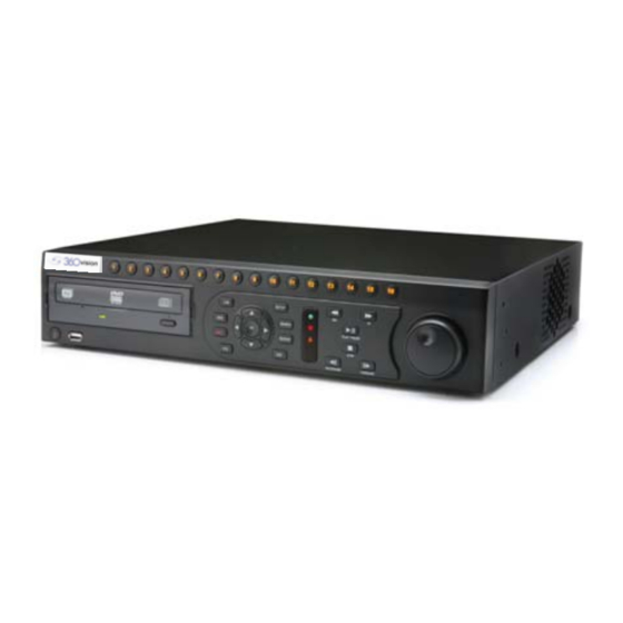
1.1 PRODUCT DESCRIPTION T series is a premier embedded DVR based on enhanced MPEG-4. It offers real-time live display and recording capabilities as high as 480FPS/ 400FPS. The strong and seamless networking function gives a convenient way for live viewing and complete control/management of the remote DVR over the internet. -
Page 15: Key Features
1.2 KEY FEATURES The T series features the following aspects. Enhanced MPEG4 • Recording Speed • 480/400fps SXGA Live Display at 1280x1024 • Intuitive User-friendly Interface • Emergency Backup • Independent Recording Setup by Each Channel • Provides Dual-stream for Recording and Networking •... -
Page 16: Specification
1.3 SPECIFICATION... -
Page 17: T7016
1.3 SPECIFICATION 1.3.2 T7016 Model General Video Format NTSC / PAL Video Input 16 CHs Video Output 1 Composite, 1 S-Video, 1 VGA (D-Sub) Spot 1CH / loopback 16CHs Display Mode 1, 4, 9, 16, PIP Display Speed Real-time Live Display (720x480/720x576) (NTSC/PAL) Recording Resolution 720x480 / 720x240 / 352x240 (NTSC) 720x576 / 720x288 / 352x288 (PAL) -
Page 18: Getting Started
GETTING STARTED... - Page 19 NOTE NOTE...
-
Page 20: Front Panel
2.1 FRONT PANEL 2.1.1 2.1.2 2.1.9 2.1.3 2.1.4 2.1.5 2.1.4 2.1.6 – 2.1.7 2.1.8 * The illustration may slightly differ in appearance of the real DVR unit. 2.1.1 NUMERIC BUTTONS It allows you to select the desired channel(camera) or input a number. In the live/search mode, select the desired channel(camera) •... -
Page 21: Function Buttons
2.1 FRONT PANEL 2.1.4 FUNCTION BUTTONS LIVE: Press to switch display mode in the fixed sequence as shown • below. Single 4-split 9-split 16-split ..Single SEQ: Press to automatically change display mode in the fixed • sequence according to the current display mode as shown below. Single Channel Display Mode CH16 4-Split Display Mode... - Page 22 2.1 FRONT PANEL 9-Split Display Mode CH9 CH10 CH11 CH12 CH13 CH14 CH15 CH16 PiP(Picture in Picture) Mode CH16 REC: Press to perform instant recording • • Press once, enter the pan/tilt mode. You can move the view of • PTZ cam using the Directional Buttons Press twice, change the zoom/focus mode to the zoom/focus.
-
Page 23: Directional / Ok Buttons
2.1 FRONT PANEL 2.1.5 DIRECTIONAL / OK BUTTONS Directional Buttons: are used to navigate through the menu items, • move PTZ camera’s view or operate PTZ functions such as pan/tilt and zoom/focus. 1. In the live monitoring or search mode, LEFT/RIGHT: press to change the channel(s) to the previous/next one(s) in the same display mode. -
Page 24: Playback Control Buttons
2.1 FRONT PANEL 2.1.8 PLAYBACK CONTROL BUTTONS These buttons allows you to control a playback. In the search mode, • Press to play forward recorded images Every time the FAST FORWARD button is pressed, the playback rate will increase 2 times up to 32x. -
Page 25: Jog/Shuttle
2.1 FRONT PANEL 2.1.9 JOG / SHUTTLE Jog/shuttle user interface is used to manipulate the playback in an efficient way. Jog: the inner dial • Turn this dial to the left to step back a recorded image one by one. Turn this dial to the right to step forward a recorded image one by one. -
Page 26: Rear Connectors
2.2 REAR CONNECTIONS 2.2.1 CONNECTING PERIPHERAL DEVICES Install the DVR on flat surface. If required, attach a rubber mount for installation. In case that 19-inch rack is used, it is recommend to install the system on shelve and use 2.5~3U (1U=1.75 inch or 4.45 cm) space for proper ventilation. -
Page 27: Remote Controller
2.3 REMOTE CONTROLLER 2.3.1 REMOTE CONTROLLER The buttons on the IR remote controller operate in the same way buttons on the front panel do. Power Button ID Button Numeric Buttons PTZ Control Focus Control Preset PTZ Tour Zoom In/Out Directional Buttons 10. -
Page 28: How To Use Remote Controller
To use the remote controller, you must set the remote controller ID to the REMOTE ID of the DVR. When more than one T series DVR is installed in the same location, you can use only one remote controller to operate multiple DVRs at once or one by one according to the REMOTE ID settings of DVRs. -
Page 29: System Startup And Shutdown
2.4 SYSTEM STARTUP AND SHUTDOWN 2.4.1 SYSTEM STARTUP After connecting all peripheral devices, connect the power cord to the DVR for system startup. Login as an administrator after switching on the power button. User can log in as the other users if new users have been added in the USER setup. -
Page 30: System Shutdown
2.4 SYSTEM STARTUP AND SHUTDOWN 2.4.2 SYSTEM SHUTDOWN To turn off the power, Click TOOL button and then click SHUTDOWN in the GUI software as below. Do not pull off the power by pulling the power plug. NOTE User can input password through the virtual keypad, or using the front numeric buttons. - Page 31 NOTE NOTE...
-
Page 32: Operation
OPERATION... - Page 33 NOTE NOTE...
-
Page 34: Login
3.1 LOGIN 3.1.1 LOGIN For the first time system start-up, the login box appears and allows you not to operate the DVR until logging in as an authorized user. In the live mode, you can change the login user by clicking TOOL >> USER or pressing FAST FOWARD button on the front panel. -
Page 35: Channel Selection
3.2 LIVE DISPLAY MODE 3.2.1 CHANNEL SELECTION Real-time live image can be seen by easy button operation after power-on. The images can be seen on real-time by 1, 4, 9, 16 and PiP screen. If the up/down arrow button on the front panel or IR remote controller is pressed, the screen will be sequentially changed. -
Page 36: Icons
3.2 LIVE DISPLAY MODE 3.2.2 ICONS In real time live mode, icons or messages will be indicated on the screen to notify the system mode or status. Below are the icon categories, which are indicated on the monitor. Icon to be shown at right-upper corner on Icon to be shown at right-bottom corner on full each channel screen screen. -
Page 37: Live Display Mode
3.2 LIVE DISPLAY MODE This icon means “instant (emergency) recording”, which is useful to urgently start recording. In emergence recording, the system maximizes the full recording frames to allocate it to all the channels available equally at 1CIF resolution. This icon means “PTZ” mode, which is useful to instantly switch to PTZ control. -
Page 38: Popup Menu
3.2 LIVE DISPLAY MODE 3.2.3 POPUP MENU User can click the right button of the mouse to pop up sub-menu as below. When “SEQUENCE” is selected, icon is shown on the bottom right of the screen and displayed channels will be sequentially changed. When “ZOOM”... - Page 39 3.2 LIVE DISPLAY MODE “NO SIGNAL” is shown on the display screen when no camera is connected or camera is disconnected on a certain channel. When camera is disconnected, warning sound shall be generated according to the system setting. Admin user can set different level of authorization for each user. If a certain user is not allowed to view a certain live and playback channel, then “NO PERMISSION”...
-
Page 40: Ptz
3.3 PTZ 3.3.1 PTZ User can get into PTZ mode by right click and select “PTZ” on the pop-up menu, or select “PTZ” icon in the menu bar appeared on the bottom of the main screen. In the PTZ mode, user can control PTZ operation with USB mouse. While pressing the left button of mouse, user can drag the mouse pointer to the up/down or left/right to move pan/tilt position of the camera. - Page 41 3.3 PTZ In the same way, user can select preset button or exit PTZ screen mode. NOTE User will see numeric pad to select “Preset” number, once after user set a PTZ protocol in setting menu. Maximum Preset number is 255. User can automatically switch PTZ camera position according to the sequence of preset setting by using “GUARD TOUR”...
-
Page 42: Search
3.4 SEARCH 3.4.1 BASIC SEARCH Press PLAY button on the front panel, and the latest recording data will start playing back. Using the playback control icons or the Jog/Shuttle on the front panel, you can search recording in a various way and also control the speed of the playback 2, 4, 8, 16, or 32 times to the forward or backward User can click button on the bottom tool bar to automatically play... -
Page 43: Quick Backup In The Search Mode
3.4 SEARCH 3.4.2 QUICK BACKUP IN SEARCH MODE User can easily archive video while he/she watches video playback. In the search mode, user can press “OK” button on the front panel to set archive “start” time. After pressing this "OK" button, user will see “Quick backup starts”... -
Page 44: Calender Search
3.4 SEARCH 3.4.3 CALENDER SEARCH The user can select a specific date and time to search for recordings. The user can move the white-vertical line indicator to select a specific date and time for search. The colors of the time bar are different according to the recording method. Time bars in color are shown by 4 channel group. -
Page 45: Search Date / Time
3.4 SEARCH 3.4.4 SEARCH DATE / TIME Enter the desired date and time for the user to playback the recorded image. Use the arrow button to move to each day/month/year and time category for selecting second/minute/hour/month/year. -
Page 46: First Data
3.4 SEARCH 3.4.5 FIRST DATA Go to the first frame of the recorded data. This is the oldest image recorded. 3.4.6 LAST DATA Go to the last frame the recorded image. This is the latest image recorded. NOTE User can press “SEARCH” button in the front panel to get the SEARCH pop-up menu as below. -
Page 47: System Log
3.4 SEARCH 3.4.7 SYSTEM LOG The system log search is used to find particular system log information, quickly and easily. User can copy this event list to built-in CD/DVD burner or USB memory device in text file format. Once export is completed, user can find a date folder created in backup media like CD/DVD or USB thumb drive. -
Page 48: Event Log
3.4 SEARCH 3.4.8 EVENT LOG The Event log search is used to find particular event, quickly and easily. User can copy this event list to built-in CD/DVD burner or USB memory device in text file format. Once CD/DVD media is inserted or USB memory stick is put via USB port, user must press “SCAN”... -
Page 49: Dst
3.4 SEARCH 3.4.9 DST During DST (Daylight Saving Time) period, DVR time clock has to be adjusted according to regional time zone. That is, DVR time clock will be shifted by one hour after DST setting while DVR will restore the time clock to normal after DST finishes. - Page 50 3.4 SEARCH When user click on such overlapped period, a message of “Data Selection” will pop up, then user can select whether to play DST data or Non-DST data. Click OK to play DST image. Click CANCEL to play Non-DST image.
- Page 51 NOTE NOTE...
-
Page 52: Setup
SETUP... - Page 53 NOTE NOTE...
-
Page 54: Setup Menu
4.1 SETUP MENU 4.1.1 SETUP OVERVIEW Setup consists of “System”, “Device”, “Record”, “Network”, “Backup” and “Quick Setup” as below. Main Classification Sub Classification SYSTEM INFO USER SYSTEM EXPORT/IMPORT FACTORY DEFAULT CAMERA SENSOR DEVICE MOTION ALARM EXTRA ALARM AUDIO CAMERA RECORD SCHEDULE NETWORK NETWORK... -
Page 55: System
4.2 SYSTEM To configure the preferred settings, go to TOOL >> SETUP on the bottom menu bar or press the SETUP button on the front panel. In the setup mode, you can change all settings related to the DVR, manage user accounts, and back up recorded images. -
Page 56: System Info
4.2 SYSTEM 4.2.1 SYSTEM INFO This is to check system information status or change the system-related configuration. User can move to other sub-menu of the System ; System Info, User, Export/Import, HDD, and Factory Default by moving mouse pointer or pressing the front arrow buttons. - Page 57 4.2 SYSTEM In “DATE/TIME SET”, user can activate DST(Daylight saving time), and select time synchronization server, besides of basic settings like time zone/time format. NOTE Video images might be heavily shaking and blinking in probably black & white if NTSC/PAL is not properly set. User needs to make sure of NTSC/PAL setting fit to electric standard of user’s location.
- Page 58 4.2 SYSTEM SITE ID : user must setup SITE ID to match with the ID setting in keyboard, if user wants to use keyboard to control DVR. User also needs to select correct KEYBOARD model and BUAD RATE setting. REMOTE ID : user must setup REMOTE ID to match with the ID setting in IR remote controller, if user wants to use IR remote controller to control DVR.
- Page 59 4.2 SYSTEM In “Display Setting”, user can set sequence dwell time, spot-out dwell time, the spot-out channel, and OSD as below picture. User can set spot-out & sequence dwell time in this menu as well as OSD show/no-show. Alpha blending is the transparency level of the menu screen. 100% means no transparency at all.
-
Page 60: User
4.2 SYSTEM 4.2.2 USER You are allowed to add a new user, change settings of the specific user, delete the specific user account, or change login options in this setup menu. To add a new user, Click ADD button. The following window appear. Input a preferred user name and password. - Page 61 4.2 SYSTEM To change settings of the specific user, Select the specific user account on the user list. Click EDIT button. The USER ADD/EDIT window appear. Change settings and click OK button. To delete the specific user account, Select the specific user account on the user list. Click DELETE button.
-
Page 62: Export / Import
4.2 SYSTEM 4.2.3 EXPORT / IMPORT User can copy and paste the system configuration values in this menu. “Export” means when user want to copy the setting values of this system to USB memory devices. “Import” means when user want to call up the setting values of other system from CD/DVD/USB memory devices. -
Page 63: Hdd
4.2 SYSTEM 4.2.4 HDD HDD information is shown in this menu. (S-ATA HDD is used in this system) User can select “Overwrite” or “Stop recording” when HDD becomes full. User also can easily format new HDD or existing HDD. The number of maximum built-in HDD units is dependent on a model. If system resources are occupied such as network connection or image playback during format process, format may be failed. -
Page 64: Factory Default
4.2 SYSTEM 4.2.5 FACTORY DEFAULT With authorized password, user can get the system back to factory default configuration. NOTE Upon clicking “OK” button, all the configuration values made by user will be deleted. The system setting will be originated by factory defaults. -
Page 65: Device
4.3 DEVICE 4.3.1 CAMERA “Covert” is to hide camera display and playback as if there is no camera recording, so called “hidden camera” feature. Default motion area setup is to select entire camera area. -
Page 66: Ptz
4.3 DEVICE 4.3.2 PTZ Full control of PTZ camera is available in this menu. “M” (Depending on the model of PTZ camera) If selected, the OSD menu of PTZ camera is imported and shown on • the DVR monitor and hence user can make full PTZ setting. Protocol Select the proper protocol of the connected PTZ camera. - Page 67 4.3 DEVICE How to setup PTZ camera with 360 Vision protocol (example) Make sure of serial communication with the PTZ camera through RS- 484 port. Select “VISION - 360” in the protocol list, and set address. Set baud rate to 9600.
-
Page 68: Sensor
4.3 DEVICE 4.3.3 SENSOR “Intensive” means that the system increases recording speed up to the maximum frame at the selected resolution upon alarm triggered during the selected dwell time. The recording speed of all other channel will be automatically decreased during alarm-triggered intensive recording, and also will trigger alarm signal via the selected sensor-out channel. - Page 69 4.3 DEVICE PRESET User can select the camera to move to preset position, once the • sensor is triggered. (User should setup preset position in PTZ menu 4.2.6 in advance) DWELL (Post Alarm) Set the recording period from the start of sensor input activation. •...
- Page 70 4.3 DEVICE NOTE Check the setting of the sensor type (N/O or N/C), if the sensor does not operate properly. The alarm might not function if the actual connecting sensor type and the sensor type in the system setting are inconsistent. NOTE “Camera pop-up”...
-
Page 71: Motion Alarm
4.3 DEVICE 4.3.4 MOTION ALARM Motion alarm is to record only when motion detection is triggered by DVR S/W upon user’s motion area setting. The system records at maximum recording speed upon motion detection if user sets “on” in “Intensive” during selected dwell time and pre-alarm, and also will trigger alarm signal via the selected sensor-out channel. -
Page 72: Extra Alarm
4.3 DEVICE 4.3.5 EXTRA ALARM S.M.A.R.T. alarm is to trigger alarm signal when HDD might be about to be out of operation. This alarm is created by HDD and captured by DVR. If HDD does not create this alarm, then DVR also does not capture and output and signal either. -
Page 73: Audio
4.3 DEVICE 4.3.6 AUDIO [200/240 fps Recoding Model] User can select 4 Ch audio input and 1 Ch audio output during live • display, and match the audio input to a designated channel (Please refer to Section 4.3.1 Camera Record) [400/480 fps Recoding Model] User can select 8 Ch audio input and 1 Ch audio output during live •... -
Page 74: Record
4.4 RECORD 4.4.1 CAMERA “On/Off” is to switch “recording” on and off in each channel. If recording is not required on the selected channels, even when the camera signal is inputted, set the recording of the corresponding channel as [OFF]. Then, recording of the channel stops without pulling camera BNC cable off. - Page 75 4.4 RECORD “Auto Del”, in full name of auto deleting, means that the system will overwrite video whatever is recorded longer than the number of days set by “Auto Del” in accordance with privacy regulation in certain country. “Audio” Ch # can be selected for each video channel. NOTE “Auto Del”...
- Page 76 4.4 RECORD NOTE For the same resolution, frame per byte size will vary according to various reasons such as recording picture quality setting, movement, complexity of the image and noise. Therefore, total recording period will differ hugely according to the image particularity.
-
Page 77: Schedule
4.4 RECORD 4.4.2 SCHEDULE Set recording schedule for each camera. First, select the camera to set schedule, or “All”. Recording can be set by each hour from 00 through 23 a day. No color - Off “Off” means no recording. Even though user set recording frames and •... - Page 78 4.4 RECORD If user sets “OFF” in “MOTION ALARM” of “DEVICE” and sets “CONT + • MOT” in “SCHEDULE”, then the system will not record anything even though motion is detected in motion area. Dark orange color - “Continuous” + “Sensor-activated” recording The system records all the time by “continuous”...
- Page 79 4.4 RECORD NOTE In case the recording schedule is set by “CONT + MOT” or “MOT + SENS”, then the system records by continuous or motion detection mode in normal operation. However, when motion is occurred in motion area or alarm is activated, then recording mode will be automatically switched to intensive recording as set by “MOTION”...
-
Page 80: Network
4.5 NETWORK 4.5.1 NETWORK The system has built-in web server. Network type Select network connect type. Select either LAN for fixed IP or DHCP • for dynamic IP. Gateway This is the IP address of the network router or gateway server. It is •... -
Page 81: Ddns
4.5 NETWORK 4.5.2 DDNS DDNS is to use Dynamic IP server that is operated by manufacturer. User has to tick on “Use DDNS” check-box to use it. DDNS server “cctv-link.net” is the fixed domain name of DDNS server operated by •... -
Page 82: Notification
4.5 NETWORK 4.5.3 NOTIFICATION Remote Notify The system can notify an alarm message to the IP address of Remote • Manager PC over the network. User can choose various different kinds of alarms by pressing “ADD” • for such as Log-in/Out, System start, Sensor, Video loss, Recording failure, Setup, Shutdown, Motion alarm, S.M.A.R.T., and HDD full. - Page 83 4.5 NETWORK NOTE User can set remote pop-up in RemoteManager S/W(RMS) upon alarm trigger in DVR. In order for RMS user to receive an instant pop-up video over network from DVR, DVR user has to tick “SENSOR” or “MOTION ALARM” in above menu. “SENSOR”...
-
Page 84: Backup
4.6 BACKUP 4.6.1 BACKUP The DVR allows you to archive recordings to an ODD media or USB memory. To back up recorded data, Select BACKUP and go to BACKUP. The BACKUP main window appears as shown below. Choose the desired channels to be archived. Set FROM and TO. -
Page 85: Backup Viewer
4.6 BACKUP 4.6.2 BACKUP VIEWER Once insert the CD, the Backup Viewer will automatically run. You can play back the backup video clips. To play back the backup data through the Backup Viewer, Click button on the backup viewer. The File Search window appears. Step# 4 Step# 3 Step# 5... - Page 86 4.6 BACKUP Double click a desired channel on the list. You can search the backup video clip with the playback controls. Print a still image Convert to .avi format Save a still image Backup Viewer Options Zoom in/out NOTE Converting archived videos, you will be asked to input a password. This is a valuable way to protect converted files against counterfeits.
-
Page 87: Backup Viewer Options
4.6 BACKUP 4.6.3 BACKUP VIEWER OPTIONS The Backup Viewer has options and allows you to optimize your use. The following will explain what each option is for. Use DirectDraw: is the option for a PC that do not support Direct •... -
Page 88: Quick Setup
4.7 QUICK SETUP 4.4.1 QUICK SETUP Quick Setup is to help user make simple configuration for recording resolution, entire recording speed by frame, recording mode, and recording periods. The system will put the first priority of configuration on this quick setup and will follow this rule by quick setup beyond whatever user sets configurations in other menu.
Need help?
Do you have a question about the T Series and is the answer not in the manual?
Questions and answers