
Related Manuals for Dimplex VFMQ 20


Summary of Contents for Dimplex VFMQ 20
-
Page 1: Table Of Contents
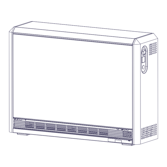
VFMQ ThermoComfort mechanic Storage Heater Installation and Operating Instructions Contents Operating Instructions Condition as Received, Installation Device Installation Electrical Connection Technical Device Information Warranty, After-Sales Service 459292.66.01 06/10/A... -
Page 2: Operating Instructions
Operating Instructions for Users English General Information • Do not insert any objects into the device or bring any objects into contact with the device. This could lead to For installation, operation and maintenance, please observe malfunctions or the objects might ignite. these instructions. - Page 3 Operating Instructions for Users English Manual Charging (Manual Operation) Temperature Management If the charging of the device is to be controlled manually, the Room Too Cold charging knob must be placed on the axis of the adjuster. • Check the breaker/fuses for the storage heaters in the Remove the cap at the front panel of the storage heater.
-
Page 4: Condition As Received, Installation
- If it can be expected that the supporting feet may sink into the flooring, so that the air exchange below the storage heater is obstructed. Dimensions of cable entry Type Dimension A VFMQ 20 24 5/8“ (626 mm) VFMQ 30 30 1/2“ (776 mm) VFMQ 40 36 1/2“ (926 mm) VFMQ 50 42 3/8“... -
Page 5: Device Installation
Device Installation English 1. Remove the packaging. Dispose of the packaging 3. Swing open the front panel to the front and remove it from material according to local regulations. the upper edging. Insert the electrical connecting lines and provide strain relief. Screw the 2 lateral wall spacers to the device back panel. - Page 6 Device Installation English 5. Remove the core room cover. Remove the central 7. Place the lower row of bricks into the core room starting fastening screw, slightly lift the core room cover, swivel it out from the right. and pull it out to the right. Position the core room cover so that the thermal insulation is not damaged.
- Page 7 Device Installation English 9. Position the second and third rows of bricks. Insert the 11. Position the top row of bricks in the same way. second heating element. Test the mobility of the heating elements. Jammed heating elements lead to noise generation. Clean the air outlet area and the switchbox.
- Page 8 Device Installation English 13. The partition and the heating element connecting leads are marked with numbers (1-6). Plug the connecting leads onto the heating element ends. Fasten loose cables to the cable harness. 14. If using an alternative heating element kit (see section „Technical Device Information“ on page 10), attach the extra rating label supplied with the heater accessories onto the marked field of the rating plate.
-
Page 9: Electrical Connection
Electrical Connection English 15. Carry out the electrical connection to the terminal strip of the device. Connection example: With heating contactor and wall-mounted thermostat. Circuit diagram legend A1/Z1, A2/Z2 - Control signal AC charge control - Series resistor for fan (not all types) - Heating contactor - Control resistors (charging) L1, L2, L3... -
Page 10: Technical Device Information
W x H x D HFi 212 1.02/1.36 kW L1/L2/GND 24 5/8“ x 26 1/2“ HFi 216 1.31/1.74 kW 216 lbs 75 lbs VFMQ 20 4 x 25 ~208/240V 16 kWh x 9 7/8“ HFi 220 1.64/2.18 kW 98 kg 34 kg... -
Page 11: Warranty, After-Sales Service
Products covered by this limited warranty have been tested and inspected prior to shipment and, subject to the provisions of this war- ranty, Dimplex warrants such products to be free from defects in material and workmanship for a period of 5 years from the date of the first purchase of such product. - Page 12 Address Dimplex North America Limited Tel. 1-800-668-6663 Internet: www.dimplex.com 1367 Industrial Road Cambridge ON Canada N1R 7G8...
Need help?
Do you have a question about the VFMQ 20 and is the answer not in the manual?
Questions and answers