
Related Manuals for Omron NE1A-EDR01

Summary of Contents for Omron NE1A-EDR01
- Page 1 Cat. No. Z912-E1-01 NE1A Series NE1A-EDR01 EtherNet/IP-DeviceNet Router OPERATION MANUAL...
- Page 2 NE1A Series EtherNet/IP-DeviceNet Router: NE1A-EDR01 Operation Manual Produced July 2007...
- Page 4 Indicates general mandatory actions for which there is no specific symbol. OMRON Product References All OMRON products are capitalized in this manual. The word “Unit” is also capitalized when it refers to an OMRON product, regardless of whether or not it appears in the proper name of the product.
- Page 5 OMRON. No patent liability is assumed with respect to the use of the information contained herein. Moreover, because OMRON is con- stantly striving to improve its high-quality products, the information contained in this manual is subject to change without notice.
-
Page 6: Table Of Contents
TABLE OF CONTENTS PRECAUTIONS ........Intended Audience ............General Precautions . - Page 7 TABLE OF CONTENTS viii...
-
Page 8: About This Manual
Please read this manual carefully and be sure you understand the information provided before attempting to install or operate the NE1A-EDR01 EtherNet/IP-DeviceNet Router. The following manu- als are also related to the NE1A-EDR01 EtherNet/IP-DeviceNet Router or NE1A-series Safety Net- work Controllers. Refer to these manuals as required during installation and operation. - Page 10 WHETHER SUCH CLAIM IS BASED ON CONTRACT, WARRANTY, NEGLIGENCE, OR STRICT LIABILITY. In no event shall the responsibility of OMRON for any act exceed the individual price of the product on which liability is asserted. IN NO EVENT SHALL OMRON BE RESPONSIBLE FOR WARRANTY, REPAIR, OR OTHER CLAIMS...
- Page 11 Application Considerations SUITABILITY FOR USE OMRON shall not be responsible for conformity with any standards, codes, or regulations that apply to the combination of products in the customer's application or use of the products. At the customer's request, OMRON will provide applicable third party certification documents identifying ratings and limitations of use that apply to the products.
- Page 12 Performance data given in this manual is provided as a guide for the user in determining suitability and does not constitute a warranty. It may represent the result of OMRON's test conditions, and the users must correlate it to actual application requirements. Actual performance is subject to the OMRON Warranty and Limitations of Liability.
- Page 14 PRECAUTIONS Intended Audience ..........General Precautions .
-
Page 15: Intended Audience
It is extremely important that a PLC and all PLC Units be used for the speci- fied purpose and under the specified conditions, especially in applications that can directly or indirectly affect human life. You must consult with your OMRON representative before applying a PLC System to the above-mentioned appli-... -
Page 16: Precautions For Safe Use
Precautions for Safe Use • Locations subject to water, oil, or chemicals • Locations subject to shock or vibration Take appropriate and sufficient measures when installing systems in the fol- lowing locations. Inappropriate and insufficient measures may result in mal- function. -
Page 17: Regulations And Standards
Regulations and Standards • The secondary circuits of the DC power supply must be isolated from the primary circuit by double insulation or reinforced insulation. • The DC power supply must satisfy the requirements for class 2 circuits or limited voltage/current circuits given in UL 508. •... -
Page 18: Overview
SECTION 1 Overview This section introduced the EtherNet/IP-DeviceNet Router and it’s functionality. EtherNet/IP-DeviceNet Router ........1-1-1 Accessing All Devices on a Network from a Network Configurator 1-1-2... -
Page 19: Ethernet/Ip-Devicenet Router
EtherNet/IP-DeviceNet Router Section 1-1 EtherNet/IP-DeviceNet Router The NE1A-EDR01 EtherNet/IP-DeviceNet Router is an FA router with one Ethernet port and one DeviceNet port, and is used for routing messages between Ethernet and DeviceNet Networks. In this manual the NE1A-EDR01 EtherNet/IP-DeviceNet Router is called the “ED Router.”... -
Page 20: Monitoring Devicenet Or Devicenet Safety Systems Via Ethernet
Safety controls can be monitored by accessing devices on the DeviceNet Safety network using the UDP service from a general-purpose controller on the Ethernet network (e.g., a PLC or computer). PLC (OMRON or other maker) Computer Ethernet Socket service (UDP) -
Page 21: Nomenclature
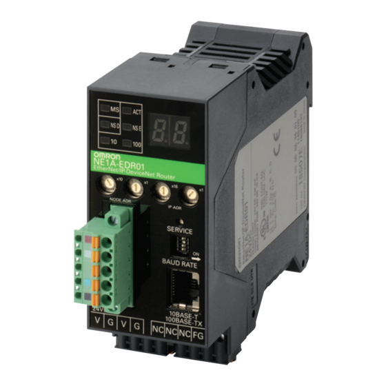
Nomenclature Section 1-2 Nomenclature The following illustration shows the part names of the ED Router. 7-segment display Status indicators EtherNet/IP DeviceNet node IP address switches address switches Service switch DeviceNet DeviceNet communications communications connector baud rate switch Ethernet connector Power supply connector Ground connector... -
Page 22: Installation And Network Connections
SECTION 2 Installation and Network Connections This section describes how to install and connect the networks. Installation........... . 2-1-1 Requirements for Installation and Wiring . -
Page 23: Installation
Section 2-1 Installation Installation 2-1-1 Requirements for Installation and Wiring Take the following into account during installation to improve the reliability of the system and to fully utilize the system's capabilities. Installation and Do not use or store the ED Router in the following locations. Storage Environment •... - Page 24 Installation Section 2-1 Wiring duct 50 mm max. 35-mm DIN Track 5 mm max. 5 mm max. End Plate Model: PFP-M End Plate Model: PFP-M 50 mm max. Wiring duct Note The ED Router can be mounted only to a DIN Track. Do not screw the Router to the control panel.
-
Page 25: Ed Router Dimensions And Weight
Section 2-1 Installation 2-1-3 ED Router Dimensions and Weight Dimensions 45.2 131.4 114.1 101.1 (Unit: mm) 105.1 Weight Model Weight NE1A-EDR01 220 g max. -
Page 26: Wiring
Section 2-2 Wiring Wiring 2-2-1 General Instructions on Wiring Precaution: • To prevent wire clippings from getting into the ED Router, do not remove the label on the ED Router before wiring has been completed. • After wiring has been completed, be sure to remove the label from the Controller to enable heat dissipation for proper cooling. - Page 27 Section 2-2 Wiring Model of pin terminal Wire dimensions Pin terminal specifications Cross- Stripped Overall Length of Inner Inner sectional length of length L1 metal diameter of diameter of area of insulation (mm) part L2 conductor insulative conductor (mm) (mm) D1 (mm) cover D2 (mm)
-
Page 28: Devicenet Wiring
Wiring Section 2-2 ED Router Other devices ED Router Other devices ED Router Other devices Ground with max. resistance of 100-Ω Independent ground: Correct Shared ground: Incorrect Note Ground correctly to avoid malfunctioning due to noise. 2-2-3 DeviceNet Wiring Wiring Cables Wire the DeviceNet communications cable as shown in the following diagram. -
Page 29: Ethernet (Ethernet/Ip) Network Installation
Wiring Section 2-2 Note Refer to the DeviceNet Operation Manual (W267) for further information on wiring. 2-2-4 Ethernet (EtherNet/IP) Network Installation Basic Installation • Take the greatest care when installing the Ethernet System, being sure to Precautions follow ISO 8802-3 specifications. You must obtain a copy of these specifi- cations and be sure you understand them before attempting to install an Ethernet System. - Page 30 Section 2-2 Wiring Connect shield. Connector Connector Connector Connector Connector Do not connect shield. ED Router Connector terminal (Shield) (Shield) ED Router Connector terminal (Shield) • Press the cable connector in firmly until it locks into place at both the switching hub and the ED Router.
- Page 31 Wiring Section 2-2 Note Adjust the ED Router link settings to match the communications settings of the connected switching hub. If the settings do not match, the link will become unstable and prevent normal communications. The following table shows the allowed settings for each switching hub communications mode.
- Page 32 Section 2-2 Wiring ED Router 35 mm 1,2,3... 1. Lay the twisted-pair cable. 2. Connect the cable to the switching hub. Be sure to press in the cable until it locks into place. This procedure should only be performed by qualified personnel.
-
Page 33: Connecting To Devicenet
Section 2-3 Connecting to DeviceNet Connecting to DeviceNet 2-3-1 Setting the DeviceNet Node Address Set the DeviceNet node address using the rotary switches (NODE ADR) on the front of the ED Router. Method Two-digit decimal number Range 0 to 63 Note The node address is set to 63 at the factory. -
Page 34: Devicenet Node Address And Baud Rate Software Settings
Use the following procedure to set the ED Router DeviceNet node address and baud rate from the Network Configurator. 1,2,3... 1. Select Programs - OMRON Network Configurator for DeviceNet Safety - Network Configurator from the Start Menu. The Network Configurator will be started. -
Page 35: Connecting To Ethernet (Ethernet/Ip)
Section 2-4 Connecting to Ethernet (EtherNet/IP) Connecting to Ethernet (EtherNet/IP) 2-4-1 Setting the IP Address This section describes methods for setting the IP address for the ED Router. Method 1: The default IP address is 192.168.250.IP_address_switch_set value. The IP address is set with the rotary switches on the front of the ED Router (IP ADR). -
Page 36: Tcp/Ip Configuration
Settings with the Network Configurator 1,2,3... 1. Select Programs - OMRON Network Configurator for DeviceNet Safety - Network Configurator from the Start Menu. The Network Configurator will be started. 2. Connect the Network Configurator online. (First set the interface with Op- tion - Select Interface, and then select Network - Connect.) - Page 37 Section 2-4 Connecting to Ethernet (EtherNet/IP) 5. For the Target IP Address, specify the present IP address of the ED Router for which the IP address is to be set. 6. To change the IP address, select Use the following IP address and then set the new IP address.
-
Page 38: Subnet Mask
Connecting to Ethernet (EtherNet/IP) Section 2-4 TCP/IP Setting Details The ED Router TCP/IP Configuration settings include the following settings. • IP address • Subnet mask • Default gateway • Preferred DNS server • Alternate DNS server • Domain name • Link setting IP Address Sets the ED Router local IP address. - Page 39 Connecting to Ethernet (EtherNet/IP) Section 2-4 Note Adjust the ED Router link settings to match the communications settings of the connected switching hub. If the settings do not match, the link will become unstable and prevent normal communications. The following table shows the allowed settings for each switching hub communications mode.
-
Page 40: Ed Router Settings
Select a number from 1,024 to 65,535 for the UDP port to be used for device access by UDP. 1,2,3... 1. Select Programs - OMRON Network Configurator for DeviceNet Safety - Network Configurator from the Start Menu. The Network Configurator will be started. - Page 41 ED Router Settings Section 2-5...
-
Page 42: Status Indicators And Troubleshooting
SECTION 3 Status Indicators and Troubleshooting This section describes how to interpret the status indicators and how to troubleshoot problems that may occur with the ED Router. Status Indicators ..........3-1-1 Overview. -
Page 43: Status Indicators
Section 3-1 Status Indicators Status Indicators This section describes the ED Router status indicators (LEDs). 3-1-1 Overview ED Router and network status are displayed on the following status indicators. • MS (Module Status): Displays the status of the ED Router. •... -
Page 44: Seven-Segment Display
Status Indicators Section 3-1 3-1-2 Seven-segment Display This section describes the meanings of the 7-segment display. Normal Status When no error has occurred and communications are enabled, the ED Router DeviceNet node address is displayed as the initial status on the 7-segment display. - Page 45 Section 3-1 Status Indicators • Display Example: When IP Address is 192.200.200.2 The IP address moves across the display from right to left. 300 ms Not lit 300 ms Not lit 300 ms Not lit 300 ms Not lit 50 ms. 50 ms.
-
Page 46: Troubleshooting
Section 3-2 Troubleshooting Troubleshooting 3-2-1 ED Router Errors and Error Processing Indicators/Display Error Cause ED Router Error Countermeasures operation code NS D NS E 7-seg- (hex) ment Hardware-related Errors Lit red Not lit Not lit Not lit System error ED Router fail- Operation stops. - Page 47 Section 3-2 Troubleshooting Indicators/Display Error Cause ED Router Error Countermeasures operation code NS D NS E 7-seg- (hex) ment DeviceNet Communications-related Errors Lit red --- Node The ED Router DeviceNet opera- 0211 Check the node addresses address DeviceNet node tion stops. and the network connections duplication address is the...
- Page 48 Section 3-2 Troubleshooting Indicators/Display Error Cause ED Router Error Countermeasures operation code NS D NS E 7-seg- (hex) ment Flash- Flash- Invalid IP The IP address Operation contin- 0214 Check the IP address switch address set- is set to be ues, using the setting and the configura- ting...
-
Page 49: Error History
Section 3-3 Error History Error History The error history records errors that the ED Router detects, along with the total operating time of the ED Router. The results recorded in the error history can then be read or cleared from the Network Configurator. Depending on the contents of the error history, some parts are cleared and some are not cleared when the CPU Unit power is turned OFF or reset. - Page 50 Section 3-3 Error History When the error history is read using the Network Configurator, the time at which the error occurred (the ED Router total operating time), error informa- tion, detailed error information, and the contents of the error are displayed as shown in the following illustration.
-
Page 51: Error History Code List
Section 3-3 Error History 3-3-2 Error History Code List Error Error Detailed information Non- code volatile 1st byte 2nd byte (hex) memory 0118 Illegal message discarded FF hex FF hex Not stored 020F Ethernet communications controller 00 hex 01 hex Stored error 0211 Ethernet IP address duplication error Port No. - Page 52 Section 3-3 Error History Error Error Detailed information Non- code volatile 1st byte 2nd byte (hex) memory 0601 System error Undetermined Undetermined Stored 0602 Memory access error 01 hex: Read error 06 hex: Error history Stored (See note.) 02 hex: Write error 07: Protocol data 09 hex: Identity data 0E hex: Unit name...
- Page 53 Section 3-3 Error History...
-
Page 54: Accessing Devices By Udp
SECTION 4 Accessing Devices by UDP This section describes how to access network devices using UPD. Overview ........... . . 4-1-1 Accessing Devices by UDP/IP . -
Page 55: Overview
Safety controls can be monitored by accessing devices on the DeviceNet Safety network using the UDP service from a general-purpose controller on the Ethernet network (e.g., a PLC or computer). PLC (OMRON or other maker) Computer Ethernet Socket service (UDP) -
Page 56: Formats
Section 4-2 Formats Formats 4-2-1 Command Format This section describes the format for UDP/IP messages (i.e., commands) sent from a device on an Ethernet network. The LSB is placed in the rightmost address for each parameter. When this command is sent from a device on the Ethernet network to the ED Router, an Explicit Message is sent to the destination node on the DeviceNet network. -
Page 57: Response Format
Section 4-2 Formats Parameter Description Instance ID Sets the instance ID for the destination object. The instance ID set here is sent to the destination node as Data Sets the data. The contents of the data vary depending on the service code. 4-2-2 Response Format When a response is returned from the destination device on the DeviceNet... -
Page 58: Operating Examples
Ethernet network using UDP/IP frame message communications via an ED Router. In this example, a Mitsubishi CPU Module and a Mitsubishi Ethernet Interface Module on an Ethernet network monitor an NE1A-series or DST1-series device using UDP/IP message communications via an NE1A-EDR01 ED Router. Mitsubishi products IP address: 192.168.250.18... - Page 59 Operating Examples Section 4-3 Network Parameter Settings (Refer to 4-4-2 Network Parameters.) • Ethernet operation settings • Initial settings • Open settings Creating Ladder Programs (Refer to 4-5 Sample Ladder Programs.) Note For advanced monitor settings, refer to 4-6 NE1A Series Monitoring and 4-7 DST1 Series Monitoring.
-
Page 60: Mitsubishi Ethernet Interface Module Settings
Section 4-4 Mitsubishi Ethernet Interface Module Settings Mitsubishi Ethernet Interface Module Settings This section describes how to make the settings for the Mitsubishi QJ71E71- 100 Ethernet Interface Module. Note Refer to the following manuals for more details on subjects such as proce- dures for making settings. - Page 61 Destination IP Set the IP address for the remote device. 192.168.250.17 address (NE1A-EDR01) Dest. Port No. Set the port number for the remote device. FA00 hex (64,000 decimal) Note For this item, be sure to make the same setting as shown in the Set-...
-
Page 62: Sample Ladder Programs
In this example, a Mitsubishi CPU Module and a Mitsubishi Ethernet Interface Module on an Ethernet network monitor the safety input terminals of an NE1A-SCPU01-V1 or DST1-ID12SL-1 using UDP/IP message communica- tions via an NE1A-EDR01 ED Router. Mitsubishi products IP address: 192.168.250.18... -
Page 63: Pc Parameters
Section 4-5 Sample Ladder Programs 4-5-2 PC Parameters The following table shows the locations in CPU Module memory of the data used in the sample ladder programs. Address Contents Remarks D100 OPEN instruction execution type D101 OPEN instruction completion sta- D200 System area D201... -
Page 64: Sample Ladder Program Processing Flow
Sample Ladder Programs Section 4-5 4-5-3 Sample Ladder Program Processing Flow The following flowchart shows the flow of processes in the sample ladder pro- grams. Initial processing # Executed automatically. Connection Connection open processing open processing Connection open successful? Abnormal completion signal M101 turns ON and the error code is stored in the completion status area (D101). - Page 65 Section 4-5 Sample Ladder Programs Note (1) The BUFSND instruction is a special instruction for Ethernet Modules, used to send data to remote devices using fixed buffer communications. (2) The BUFRCV instruction is a special instruction for Ethernet Modules, used for reading data received from remote devices using fixed buffer communications.
-
Page 66: Sample Ladder Programs
Section 4-5 Sample Ladder Programs 4-5-4 Sample Ladder Programs This section provides sample ladder programs, in order, for the processes indicated in the flowchart. Connection Open Processing SM402 G20480 K4M0 Open Connection ON for completion 1 open 1 scan signal completion after signal... - Page 67 Section 4-5 Sample Ladder Programs Status Monitor This section provides, in order, the sample programs for acquiring NE1A- Processing SCPU01-V1 and DST1-ID12SL-1 safety input monitor data. Example: Monitoring The settings for acquiring the safety input monitor data are shown here. NE1A-SCPU01-V1 Safety Input Terminals ■...
- Page 68 Section 4-5 Sample Ladder Programs ■ Request Message Transmission Processing M150 N3000 SEND OPEN Initial Connection 1 instruction instruction normal open 1PLS normal completion completion completion signal signal N3000 D300 Data length SEND setting instruction (number of 1PLS words) H0FF D301 Message Sequential...
- Page 69 Section 4-5 Sample Ladder Programs M300 M301 M600 BUFSND BUFSND BUFSND instruction instruction instruction normal completion abnormal completion device device M301 M601 BUFSND BUFSND instruction instruction abnormal abnormal completion device...
- Page 70 Section 4-5 Sample Ladder Programs ■ Response Message Reception Processing SM400 G20480 K4M0 Open Connection Always completion 1 open signal completion signal G20480 K4M20 Open Connection completion 1 open signal request signal G20485 K4M40 Fixed buffer Fixed buffer reception 1 reception status status signal...
- Page 71 Section 4-5 Sample Ladder Programs Example: Monitoring The settings are shown here for acquiring safety input monitor data. DST1-ID12SL-1 Safety Input Terminals ■ Request Message Contents Item Setting Destination node address 01 hex Service code 0E hex Class ID 04 hex Instance ID 310 hex Send data (attribute ID)
- Page 72 Section 4-5 Sample Ladder Programs ■ Request Message Transmission Processing M150 M3000 Send OPEN Initial Connection instruction instruction normal 1 open 1PLS normal completion completion completion signal signal M3000 D300 Data length Send (number of instruction words) 1PLS H0FF D301 Message Sequential D302...
- Page 73 Section 4-5 Sample Ladder Programs M300 M301 M600 BUFSND BUFSND BUFSND instruction instruction instruction normal completion abnormal completion device completion device M301 M601 BUFSND BUFSND instruction instruction abnormal abnormal completion completion device...
- Page 74 Section 4-5 Sample Ladder Programs ■ Response Message Reception Processing SM400 G20480 K4M0 Open Connection Always completion 1 open signal completion signal G20480 K4M20 Open Connection completion 1 open signal request signal G20485 K4M40 Fixed buffer Fixed buffer reception reception 1 status status signal...
- Page 75 Section 4-5 Sample Ladder Programs Connection Close Processing M160 Connection Connection 1 close 1 open timing completion signal M160 M150 M161 Connection OPEN Connection 1 close instruction 1 close timing normal from completion remote device M700 M2000 CLOSE BUFRCV instruction instruction 1PLS normal...
-
Page 76: Ne1A Series Monitoring
Section 4-6 NE1A Series Monitoring NE1A Series Monitoring NE1A-SCPU01-V1 or NE1A-SCPU02 data can be monitored by changing to the values shown below the communications messages (service code, class ID, instance ID, and request data (attribute ID)) indicated in 4-5 Sample Lad- der Programs. - Page 77 Section 4-6 NE1A Series Monitoring Value Meaning Output ON error Error at dual channel partner Internal bit circuit error Bit error Illegal data between dual channel outputs Short-circuit detected between wires (3) Overall Status Read Data Format (Read Size: 1 Byte) Status Status Meaning...
- Page 78 Section 4-6 NE1A Series Monitoring Safety Input Terminal Monitor Format Safety Input Monitor Offset Bit 7 Bit 6 Bit 5 Bit 4 Bit 3 Bit 2 Bit 1 Bit 0 (bytes) Safety input Safety input Safety input Safety input Safety input Safety input Safety input Safety input...
-
Page 79: Monitoring The Ne1A-Scpu02
Section 4-6 NE1A Series Monitoring 4-6-2 Monitoring the NE1A-SCPU02 Service code Class ID Instance ID Request data (attribute ID) Safety input terminal monitor Safety input monitor 4B hex 306 hex 01 hex 00000005 hex (See note 4.) Safety input status 4B hex 306 hex 0B hex... - Page 80 Section 4-6 NE1A Series Monitoring (3) Overall Status Read Data Format (Read Size: 1 Byte) Status Status Meaning Input Power Supply Voltage Status Flag OFF: Always ON, ON: Voltage error or power supply OFF Output Power Supply Voltage Status Flag OFF: Always ON, ON: Voltage error or power supply OFF Standard I/O Communications Error Flag OFF: No error, ON: Error...
- Page 81 Section 4-6 NE1A Series Monitoring Offset Bit 7 Bit 6 Bit 5 Bit 4 Bit 3 Bit 2 Bit 1 Bit 0 (bytes) Safety input Safety input Safety input Safety input Safety input Safety input Safety input Safety input terminal No. terminal No.
- Page 82 Section 4-6 NE1A Series Monitoring Offset Bit 7 Bit 6 Bit 5 Bit 4 Bit 3 Bit 2 Bit 1 Bit 0 (bytes) Muting Reserved Muting Reserved lamp status lamp status No. 7 No. 3 Reserved Status value: 1: Normal, 0: Error...
-
Page 83: Dst1 Series Monitoring
Section 4-7 DST1 Series Monitoring DST1 Series Monitoring DST1-ID12SL-1, DST1-MD16SL-1, DST1-MRD08SL-1, or DST1-XD0808SL- 1 data can be monitored by changing to the values shown below the commu- nications messages (service code, class ID, instance ID, and request data (attribute ID)) indicated in 4-5 Sample Ladder Programs. 4-7-1 Monitoring the DST1-ID12SL-1 Service code... - Page 84 Section 4-7 DST1 Series Monitoring Read Data Format (Read Size: 1 Byte) Error cause Error Cause Value Meaning No error Illegal configuration Test signal error Internal circuit error Discrepancy error Error at dual channel partner (3) Instance ID Status held in the DST1-ID12SL-1 can be monitored by reading the in- stance IDs shown in the following table.
- Page 85 Section 4-7 DST1 Series Monitoring Instance ID: 22C Offset Bit 7 Bit 6 Bit 5 Bit 4 Bit 3 Bit 2 Bit 1 Bit 0 (bytes) Safety input Safety input Safety input Safety input Safety input Safety input Safety input Safety input terminal No.
-
Page 86: Monitoring The Dst1-Md16Sl-1
Section 4-7 DST1 Series Monitoring Offset Bit 7 Bit 6 Bit 5 Bit 4 Bit 3 Bit 2 Bit 1 Bit 0 (bytes) Safety input Safety input Safety input Safety input Safety input Safety input Safety input Safety input terminal No. terminal No. - Page 87 Section 4-7 DST1 Series Monitoring Meaning Operation Time Monitor Error Flag OFF: Within range (all I/O sets lower than monitor set value), ON: Out of range (one or more I/O sets equal to or greater than monitor set value) Connected Device Maintenance Flag OFF: Within range (all I/O points lower than monitor set value), ON: Out of range (one or more I/O points equal to or greater than monitor set value)
- Page 88 DST1 Series Monitoring Section 4-7 (4) Instance ID Status held in the DST1-MD16SL-1 can be monitored by reading the in- stance IDs shown in the following table. Instance Safety Safety Safety Safety Safety Muting Safety Test Overall ID (hex) input input input output...
- Page 89 DST1 Series Monitoring Section 4-7 Offset Bit 7 Bit 6 Bit 5 Bit 4 Bit 3 Bit 2 Bit 1 Bit 0 (bytes) Safety out- Safety out- Safety out- Safety out- Safety out- Safety out- Safety out- Safety out- put termi- put termi- put termi- put termi-...
-
Page 90: Monitoring The Dst1-Mrd08Sl-1
Section 4-7 DST1 Series Monitoring Instance ID: 341 Offset Bit 7 Bit 6 Bit 5 Bit 4 Bit 3 Bit 2 Bit 1 Bit 0 (bytes) Safety out- Safety out- Safety out- Safety out- Safety out- Safety out- Safety out- Safety out- put termi- put termi-... - Page 91 DST1 Series Monitoring Section 4-7 (2) Safety Input Error Cause When an error is indicated for the safety input status, the cause of the er- ror can be acquired by reading this information. Specify the terminal number for which the error cause is to be acquired, plus 1, for the instance ID specified at that time.
- Page 92 Section 4-7 DST1 Series Monitoring Data (status) indicated by a black dot (●) can be read. I/O Assembly Data Format Status ID: 203 Offset Bit 7 Bit 6 Bit 5 Bit 4 Bit 3 Bit 2 Bit 1 Bit 0 (bytes) Reserved Safety input...
-
Page 93: Monitoring The Dst1-Xd0808Sl-1
Section 4-7 DST1 Series Monitoring Instance ID: 333 Offset Bit 7 Bit 6 Bit 5 Bit 4 Bit 3 Bit 2 Bit 1 Bit 0 (bytes) Safety input Safety input Safety input Safety input Safety input Safety input Safety input Safety input terminal No. - Page 94 DST1 Series Monitoring Section 4-7 Meaning I/O Error Flag OFF: Normal (all I/O points normal), ON: Error (one or more I/O points abnormal) Error Flag OFF: Error, ON: Normal Connected Device Maintenance Flag OFF: Within range (all I/O points lower than monitor set value), ON: Out of range (one or more I/O points equal to or greater than monitor set value) (2) Safety Input Error Cause...
- Page 95 Section 4-7 DST1 Series Monitoring (4) Instance ID Status held in the DST1-XD0808SL-1 can be monitored by reading the instance IDs shown in the following table. Instance Safety Safety Safety Safety Safety Muting Safety Test Overall ID (hex) input input input output output...
- Page 96 Section 4-7 DST1 Series Monitoring Offset Bit 7 Bit 6 Bit 5 Bit 4 Bit 3 Bit 2 Bit 1 Bit 0 (bytes) Reserved Reset Safety input Safety input Safety input Safety input Safety input Safety input request sig- operation operation operation operation...
- Page 97 Section 4-7 DST1 Series Monitoring...
-
Page 98: Specifications And Dimensions
Appendix A Specifications and Dimensions General Specifications Item Specifications DeviceNet supply voltage 11 to 25 VDC (Supplied from communications connector.) 20.4 to 26.4 VDC (24 VDC, −15% to 10%) Device supply voltage Current DeviceNet 15 mA at 24 VDC consumption Internal logic circuits 230 mA at 24 VDC Overvoltage category Compliant with IEC 61131-2. - Page 99 Appendix A Specifications and Dimensions Item Specifications Number of CIP connections Allowable Module communica- 6,000 pps (See note.) tions bandwidth Explicit message communications Class 3 connection: Maximum message length of 502 bytes UCMM connection: Maximum message length of 502 bytes Note In this case, pps means “packets per second”...
-
Page 100: Settings From The Network Configurator
Appendix B Settings from the Network Configurator The following parameters can be set from the Network Configurator. Note Network Configurator version 2.0 or higher is required to set the ED Router parameters. EtherNet/IP or DeviceNet Network Configurator ED Router version 2.0 or higher Classification Setting Description... -
Page 101: B Settings From The Network Configurator
Appendix B Settings from the Network Configurator... -
Page 102: Glossary
Glossary Term Definition assembly Internal data in a device gathered as one group to be accessed externally. bit-strobe connection One of the connection types for I/O communications in DeviceNet standard communications. For a bit-strobe connection, the Master broadcasts a mes- sage and the Slaves that receive the message return input data. - Page 103 Glossary Term Definition cyclic connection One of the connection types for I/O communications in DeviceNet standard communications. For a cycle connection, data is sent after a set period of time elapses. A cyclic connection enables sending data on a cycle that is different from the communi- cations cycle of the Master.
- Page 104 Glossary Term Definition poll connection One of the connection types for I/O communications in DeviceNet standard communications. For a poll connection, output data is sent from the Master and Slaves that receive the output date return input data. This connection type is used for cyclic communications with Slaves that have both inputs and outputs.
- Page 105 Glossary...
-
Page 106: Revision History
Revision History A manual revision code appears as a suffix to the catalog number on the front cover of the manual. Cat. No. Z912-E1-01 Revision code The following table outlines the changes made to the manual during each revision. Page numbers refer to the previous version. - Page 107 Revision History...
- Page 108 OMRON ELECTRONICS LLC One Commerce Drive Schaumburg, IL 60173-5302 U.S.A. Tel: (1) 847-843-7900/Fax: (1) 847-843-7787 OMRON ASIA PACIFIC PTE. LTD. No. 438A Alexandra Road # 05-05/08 (Lobby 2), Alexandra Technopark, Singapore 119967 Tel: (65) 6835-3011/Fax: (65) 6835-2711 OMRON (CHINA) CO., LTD.
- Page 109 Authorized Distributor: Cat. No. Z912-E1-01 Note: Specifications subject to change without notice Printed in Japan 0707-0.5M This manual is printed on 100% recycled paper.
Need help?
Do you have a question about the NE1A-EDR01 and is the answer not in the manual?
Questions and answers