Table of Contents
Advertisement
Advertisement
Table of Contents

Related Manuals for Delta 43-355


Summary of Contents for Delta 43-355
- Page 1 2 Speed Wood Shaper (Model 43-355) PART NO. 432-09-651-0004 (01/11/02) Copyright © 2002 Delta Machinery To learn more about DELTA MACHINERY visit our website at: www.deltamachinery.com. For Parts, Service, Warranty or other Assistance, 1-800-223-7278 ( 1-800-463-3582). please call In Canada call...
-
Page 2: General Safety Rules
If you have any questions relative to a particular application, DO NOT use the machine until you have first contacted Delta to determine if it can or should be performed on the product. - Page 3 ADDITIONAL SAFETY RULES FOR WOOD SHAPERS WARNING: FAILURE TO FOLLOW THESE RULES MAY RESULT IN SERIOUS PERSONAL INJURY. DO NOT OPERATE THIS MACHINE UNTIL it is 21. ONLY SHAPE LARGE WORKPIECES when using assembled and installed according to the instructions. starting pin and collar(s).
-
Page 4: Motor Specifications
POWER CONNECTIONS A separate electrical circuit should be used for your machines. This circuit should not be less than #12 wire and should be protected with a 20 Amp time lag fuse. If an extension cord is used, use only 3-wire extension cords which have 3- prong grounding type plugs and matching receptacle which will accept the machine’s plug. -
Page 5: Extension Cords
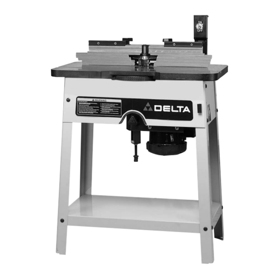
FOREWORD Delta Model 43-355 is a wood shaper. The Delta Model 43-355 has an extra large 18"x30", rectangular cast iron table which provides ample work support. The Delta Model 43-355 is equipped with a patented fence which conforms to the cutter shape for improved chip removal, dust collection and greater operator protection. -
Page 6: Assembling Stand
ASSEMBLY INSTRUCTIONS UNPACKING The shaper is shipped with the motor assembly, spindle and belt assembled to the underside of the table. Place the shaper table and motor assembly upside down on a suitable surface, such as two saw horses, making certain there is clearance for the spindle (A). IMPORTANT: The spindle assembly is double-sided, with a 1/2 inch diameter spindle on one end and a 3/4 inch diameter spindle on the other end. - Page 7 4. Assemble 3/8" rubber grommet (Z) Fig. 6, to round hole (A) in leg. 5. Assemble front panel (B) Fig. 7, to the outside of the two front legs. Insert a 5/16-18x5/8"" carriage head bolt (C) Figs. 6 and 7, through the hole in the front panel and the hole in rubber grommet (Z) Fig.
-
Page 8: Assembling Table Inserts
ASSEMBLING FENCE TO SHAPER TABLE Place the fence assembly (A) Fig. 11, on the shaper table and fasten it to the table using the two long threaded locking rods (B) and 11/32" flat washers (C), as shown. ASSEMBLING TABLE INSERTS Two table inserts (A) Fig. -
Page 9: Operating Controls And Adjustments
FASTENING SHAPER TO SUPPORTING SURFACE IF DURING OPERATION THERE IS ANY TENDENCY FOR THE SHAPER TO TIP OVER, SLIDE OR WALK ON THE SUPPORTING SURFACE, THE SHAPER MUST SECURED SUPPORTING SURFACE. HOLES (A) FIG. 16, ARE PROVIDED IN THE SHAPER LEGS FOR MOUNTING. Fig. -
Page 10: Overload Protection
CHANGING POSITION OF THE SWITCH ARM The switch arm (A) can be positioned in the vertical position, as shown in Fig. 21 , or in the horizontal position, as shown in Fig. 22. This allows the switch to be placed in the most convenient position for the type of work you are performing. -
Page 11: Fence Adjustments
FENCE ADJUSTMENTS IMPORTANT: The individual fence segments (A) should be adjusted endwise so the opening is never more than required to clear the spindle guard (B) and cutter (C), as shown in Fig. 25. To adjust the fence segments (A) endwise, loosen lock handles (D), adjust each individual fence segment (A) and tighten lock handles (D). -
Page 12: Replacing Belts
Fig. 28 Fig. 29 CHANGING SPINDLES AND REPLACING BELTS CHANGING SPINDLES The spindle assembly in your shaper is equipped with a 1/2 inch diameter spindle on one end and 3/4 inch diameter spindle on the other end. To change from one diameter to the other, proceed as follows: 1. -
Page 13: Operation
CHECKING AND ALIGNING MOTOR PULLEY TO SPINDLE 1. DISCONNECT MACHINE FROM POWER SOURCE. 2. Lift up latch (A) Fig. 34, pull out and lower front panel (B), as shown. 3. Loosen belt tension knob (C) Fig. 35 Fig. 34 4. PIace belt (D) Fig. 35, on largest step of motor pulley (E). -
Page 14: Shaping With Collars And Starting Pin
SHAPING WITH COLLARS AND STARTING PIN When shaping with collars and starting pin, the following rules must always be followed for good work and safety in operation. Fig. 39 1. Collars MUST be smooth and free of all gum or other substances. -
Page 15: Parts, Service Or Warranty Assistance
Two Year Limited Warranty Delta will repair or replace, at its expense and at its option, any Delta machine, machine part, or machine accessory which in normal use has proven to be defective in workmanship or material, provided that the customer returns the product prepaid to a Delta factory service center or authorized service station with proof of purchase of the product within two years and provides Delta with reasonable opportunity to verify the alleged defect by inspection. - Page 16 Parts and accessories for Porter-Cable ·Delta products should be obtained by contacting any Porter-Cable·Delta Distributor, Authorized Service Center, or Porter-Cable·Delta Factory Service Center. If you do not have access to any of these, call 800-223-7278 and you will be directed to the nearest Porter-Cable·Delta Factory Service Center. Las Estaciones de Servicio Autorizadas están ubicadas en muchas grandes ciudades.
Need help?
Do you have a question about the 43-355 and is the answer not in the manual?
Questions and answers