Sign In
Upload
Download
Table of Contents
Contents
Add to my manuals
Delete from my manuals
Share
URL of this page:
HTML Link:
Bookmark this page
Add
Manual will be automatically added to "My Manuals"
Print this page
×
Bookmark added
×
Added to my manuals
Manuals
Brands
General Climate Manuals
Air Conditioner
GC-S24HR
Service manual
General Climate GC-S24HR Service Manual
Room air conditioner split wall-mounted type
Hide thumbs
Also See for GC-S24HR
:
Service manual
(52 pages)
1
Table Of Contents
2
3
4
5
6
7
8
9
10
11
12
13
14
15
16
17
18
19
20
21
22
23
24
25
26
27
28
29
30
31
32
33
34
35
36
37
38
39
40
41
page
of
41
Go
/
41
Contents
Table of Contents
Troubleshooting
Bookmarks
Table of Contents
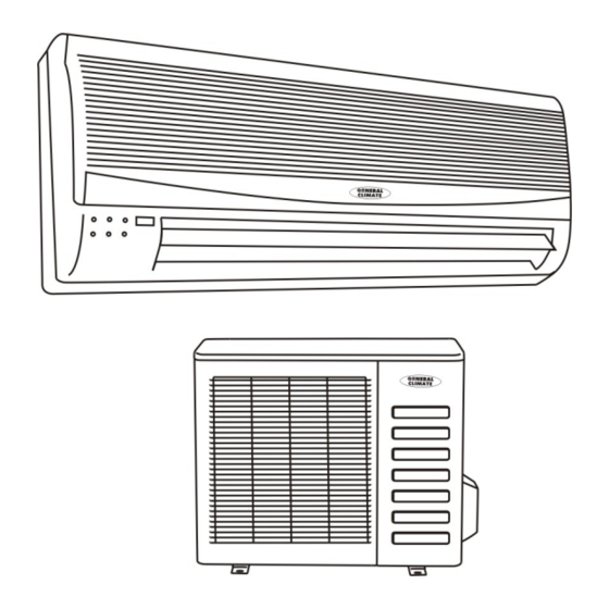
Room Air Conditioner
Service Manual
Table of Contents
1 Precaution
Safety Precaution
Warning
2 Function
3 Dimension
Indoor Unit
Outdoor Unit
4 Specification
5 Refrigerant Cycle Diagram
6 Operation Limits
Cooling Operation
Heating Operation
7 Schematic Diagram and Wiring Diagram
Schematic Diagram
Wiring Diagram
8 Installation Details
Wrench Torque Sheet for Installation
Connecting the Cables
Pipe Length and the Elevation
Air Purging of the Piping and Indoor Unit
Pumping down (Re-Installation)
Re-Air Purging (Re-Installation)
Balance Refrigerant of the 2-Way, 3-Way Valves
Evacuation
Gas Charging
9 Capacity Table
Gc/Gu-S24Hr
Gc/Gu-S30Hr
Gc/Gu-S36Hr
10 Electronic Function
Electronic Control Working Environment
Proper Symbols and Their Meaning
Function
Protection
Fan Only Mode
Cooling Mode
Dehumidifying Mode
Heating Mode
Defrosting Mode(Available for Heating Mode)
Auto Mode
Www.generalclimate.com Wall-Mounted Split Type
Force Cooling Function
Sleep Mode
Auto Restart Function
11 Model and Parameters
12 Troubleshooting
Display Board
Troubleshooting
Diagnostic Chart
Resetting Phenomenon Often Occurs During Operation
Operation Lamp Flashes and Timer Lamp off
Operation Lamp Flashes and Timer Lamp on
Operation Lamp off and Timer Lamp Flashes
Operation Lamp on and Timer Lamp Flashes
Operation Lamp Flashes, Timer Lamp Flashes
13 Characteristic of Temperature Sensor
Advertisement
Quick Links
1
Outdoor Unit
2
Wiring Diagram
3
Gc/Gu-S24Hr
Download this manual
Service manual
Room air conditioner
Split Wall-Mounted Type
GC/GU-S24HR
GC/GU-S30HR
GC/GU-S36HR
www.generalclimate.com
Wall-Mounted Split Type
Table of
Contents
Previous
Page
Next
Page
1
2
3
4
5
Advertisement
Table of Contents
Troubleshooting
Troubleshooting
36
Troubleshooting
37
Need help?
Do you have a question about the GC-S24HR and is the answer not in the manual?
Ask a question
Questions and answers
Related Manuals for General Climate GC-S24HR
Air Conditioner General Climate GC/CU-S24HR Service Manual
Room air conditioner split wall-mounted type (52 pages)
Air Conditioner General Climate GC-S30HR Service Manual
Room air conditioner split wall-mounted type (41 pages)
Air Conditioner General Climate GC-S05CR Service Manual
Split wall-mounted type (42 pages)
Air Conditioner General Climate CU-S05CR Service Manual
Split wall-mounted type (57 pages)
Air Conditioner General Climate GC/GU-S30HRI Service Manual
Room air conditioner split wall-mounted type (52 pages)
Air Conditioner General Climate GC-S07HR Service Manual
Split wall-mounted type (57 pages)
Air Conditioner General Climate GC-S09HR Service Manual
Split wall-mounted type (57 pages)
Air Conditioner General Climate GC-S12HR Service Manual
Split wall-mounted type (57 pages)
Air Conditioner General Climate GC-S18HR Service Manual
Split wall-mounted type (57 pages)
Air Conditioner General Climate ac-n9krh Instruction Manual
(10 pages)
This manual is also suitable for:
Gc-s30hr
Gu-s30hr
Gc-s36hr
Gu-s36hr
Gu-s24hr
Table of Contents
Save PDF
Print
Rename the bookmark
Delete bookmark?
Delete from my manuals?
Login
Sign In
OR
Sign in with Facebook
Sign in with Google
Upload manual
Upload from disk
Upload from URL


Need help?
Do you have a question about the GC-S24HR and is the answer not in the manual?
Questions and answers