Table of Contents
Advertisement
Advertisement
Table of Contents
Troubleshooting

Related Manuals for LG LH-T7652SB


Summary of Contents for LG LH-T7652SB
-
Page 1: Service Manual
DVD/CD RECEIVER SERVICE MANUAL MODEL : LH-T7652SB/LHS-76SBC/ LHS-76SBS/LHS-76SBW... -
Page 2: Table Of Contents
[CONTENTS] SECTION 1. GENERAL • SERVICING PRECAUTIONS ..........1-2 •... -
Page 3: Servicing Precautions
SECTION 1. GENERAL SERVICING PRECAUTIONS NOTES REGARDING HANDLING OF THE PICK-UP 1. Notes for transport and storage 1) The pick-up should always be left in its conductive bag until immediately prior to use. 2) The pick-up should never be subjected to external pressure or impact. Storage in conductive bag Drop impact 2. - Page 4 NOTES REGARDING COMPACT DISC PLAYER REPAIRS 1. Preparations 1) Compact disc players incorporate a great many ICs as well as the pick-up (laser diode). These components are sensitive to, and easily affected by, static electricity. If such static electricity is high voltage, components can be damaged, and for that reason components should be handled with care.
-
Page 5: Esd Precautions
ESD PRECAUTIONS Electrostatically Sensitive Devices (ESD) Some semiconductor (solid state) devices can be damaged easily by static electricity. Such components commonly are called Electrostatically Sensitive Devices (ESD). Examples of typical ESD devices are integrated circuits and some field-effect transistors and semiconductor chip components. The following techniques should be used to help reduce the incidence of component damage caused by static electricity. -
Page 6: Service Information For Eeprom
SERVICE INFORMATION FOR EEPROM POWER ON DETECT NEW EEPROM DVD LOGO Status (NO Disk status) (OPTION EDIT SCREEN) NAME Remotecontrol OPT 1 Pause key-->1-->4-->7-->2 in order. OPT 2 OPT 3 OPT 4 OPT 5 OPT 6 Press number 0~9, Press charater OPT 7 A~F (1~6 for a while) OPT 8... -
Page 7: Specifications
SPECIFICATIONS GENERAL Power supply Refer to main label Power consumption Refer to main label Net Weight 3.9 kg External dimensions 430 x 57 x 295 mm (W x H x D) Operating conditions Temperature: 5°C to 35°C, Operation status: Horizontal Operating humidity 5% to 85% CD/DVD... -
Page 8: Audio Troubleshooting Guide
SECTION 2. AUDIO PART AUDIO TROUBLESHOOTING GUIDE 1. POWER SUPPLY CIRCUIT... - Page 9 2. FRONT CIRCUIT (1/2) CHECK IF THE P1301 IS OK? CHECK IF THE DIS301 IS OK? P1301 Short 1pin of CN901 with 4pin of CN901 in SMPS part. PIN1 : -41 VKK PIN2 : -22 FL+ PIN3 : -26.5 FL- PIN12 : +5.0...
- Page 10 3. FRONT CIRCUIT (2/2) CHECK IF R345 ~ R350, R154 REPLACE R345 ~ R350, R154. Check if the Remocon waceform of the P3101 pin 10 is OK Check if the RM301 voltage is OK(5V) Resoldering or Replace RM301...
-
Page 12: Wiring Diagram
WIRING DIAGRAM... -
Page 13: Block Diagram
BLOCK DIAGRAM... - Page 14 CIRCUIT DIAGRAMS 1. SMPS(POWER) CIRCUIT DIAGRAM NOTE) Warning NOTES) Symbol denotes AC ground. NOTE) Parts that are shaded are critical NOTE) With respect to risk of fire or NOTES) Symbol denotes DC chassis ground. NOTE) electricial shock.
-
Page 15: Circuit Diagrams
2. POWER INTERFACE CIRCUIT DIAGRAM 2-10 2-11... - Page 16 3. µ-COM(MAIN) CIRCUIT DIAGRAM 2-12 2-13...
- Page 17 4. SERVO CIRCUIT DIAGRAM 2-14 2-15...
- Page 18 5. I/O CIRCUIT DIAGRAM 2-16 2-17...
- Page 19 6. MIC CIRCUIT DIAGRAM 2-18 2-19...
- Page 20 7. USB CIRCUIT DIAGRAM 2-20 2-21...
- Page 21 8. MIC & USB CIRCUIT DIAGRAM 2-22 2-23...
- Page 22 9. HDMI CIRCUIT DIAGRAM(OPTIONAL PART) 2-24 2-25...
- Page 23 10. FRONT CIRCUIT DIAGRAM 2-26 2-27...
- Page 24 PRINTED CIRCUIT BOARD DIAGRAMS 1. MAIN P.C. BOARD DIAGRAM ( TOP VIEW ) 2-28 2-29...
- Page 25 2. MAIN P.C. BOARD DIAGRAM ( BOTTOM VIEW ) 2-30 2-31...
- Page 26 3. SMPS P.C. BOARD 2-32 2-33...
- Page 27 4. KEY P.C. BOARD ( TOP VIEW ) ( BOTTOM VIEW ) 5. TIMER P.C. BOARD ( TOP VIEW ) ( BOTTOM VIEW ) 2-34 2-35...
-
Page 28: Electrical Troubleshooting Guide
SECTION 3. DVD & AMP PART ELECTRICAL TROUBLESHOOTING GUIDE 1. System operation flow Power On 1. 8082 initializes SERVO, DSP & RISC registers 2. Write RISC code to SDRAM 3. Reset RISC Show LOGO Tray Closed? Tray Close to Closed position SLED at Inner Side? SLED Moves to Inner Position... - Page 29 2. Test & debug flow TEST Check the AC Vol tage Check the POWER PART Power PCBA (110V or 220V) Switch on the Power PCBA Is the DC Voltage outputs OK? (-41V, -22V, Check the POWER PART -26.5V, ±12V, 5.6V, 3.3V, 5V, 7V, 32.5V) Are 3.3V and 5V DC Check the regulators or diode.
- Page 30 ES8381 Check connection lines between SDRAM(IC502) & ES8381 and the SDRAM is damaged. ES8381 Check the related circuit of ES8381 VIDEO outputs IC501 Pins133, 134, 137, 138, 139, 140 properly? Normal OPEN_SW, CLOSE_SW signal? Check the Tray control IO pins on ES8381.
- Page 31 Motor Check the connection line of Driver DRV_MUTE DRV_MUTE pin is High? Motor Check the related circuit of Driver DRV_MUTE SLEGN pin is High? SLED+ and SLED- output properly? Check Focus connection on ES8381 and motor driver.
- Page 32 Check the laser power circuit on ES8381 and connecting to power transistor.(Q405, Q406) Collector voltage of power transistor is OK? (Q405, Q406) Proper Check the related circuit on RF signal on ES8381 ES8381 RF signal. Check the RF connection between IP9009 and ES8381. Proper SPINDLE signal on ES8381.
- Page 33 Proper Check connections between signals on A, B, C, ES8381 and pick-up head. D of ES8381 Proper Check the related circuit on CD-DVDCT signal ES8381 CD-DVDCT on ES8381 Check CD_DVDCT connection between IP9009 and ES8381 Proper Check the related circuit on CD-DVDCT signal ES8381.
- Page 34 PWM IC Check connection between received correct data IC601 BCK, LRCK, ADATAO stream? Normal Check the related circuit of PWM IC out?(IC601) PWM.(Check Audio out Pins54, 55, 58, 59, 61, 62, 67, 68, 70, 71, 74, 75 Check Digital Amp circuit (IC701, IC702, IC703, IC704)
-
Page 35: Opt.
3. AUDIO µ-COM Circuit(DVD & AMP) POWER ON Does CD/DVD appear Does AV1, TV Audio, AV1 opt. at FLD? and FM 87.5 appear at FLD Does Loading appear Does it appear DVD Error at FLD? at FLD? Does no Disc or Time Check power part of Main Refer to SMPS. -
Page 36: Details And Waveforms On System Test And Debugging
DETAILS AND WAVEFORMS ON SYSTEM TEST AND DEBUGGING 1. SYSTEM 27MHz CLOCK,RESET,FLASH R/W SIGNAL 1) ES8381 main clock is at 27MHz(X501) 3.8V, 27MHz FIG 1-1 2) ES8381 reset is high active. Power Cord in 5.2VA PWR_CTL(SYSTEM µ-COM) (IC101 PIN2) DVD_RESET(IC101 PIN 41) MRST#(IC501 PIN 251) FIG 1-2... - Page 37 3) Flash R/W enable signal during download(Downloading) FRD(IC503 PIN 28) FWR(IC503 PIN 11) FIG 1-4 2. SDRAM CLOCK 1) ES8381 main clock is at 27MHz(X501) DCLK = 93MHz, Vp-p=2.2, Vmax=2.7V (IC502 PIN 38) FIG 2-1 3-10...
- Page 38 3. TRAY OPEN/CLOSE SIGNAL 1) Tray open/close waveform OPENSW(P4402 PIN3) CLOSESW(P4402 PIN4) OPEN(IC401 PIN 1) CLOSE(IC401 PIN 2) FIG 3-1 2) Tray close waveform OPENSW(P4402 PIN3) CLOSESW(P4402 PIN4) OPEN(IC401 PIN 1) CLOSE(IC401 PIN 2) FIG 3-2 3-11...
- Page 39 3) Tray open waveform OPENSW(P4402 PIN3) CLOSESW(P4402 PIN4) OPEN(IC401 PIN 1) CLOSE(IC401 PIN 2) FIG 3-3 4. SLED CONTROL RELATED SIGNAL (NO DISC CONDITION) SLO(2.0V/1.4V/1.0V) (IC501 PIN 209) DRV_MUTE(5V) – (IC401 PIN 21) SLED+(4.7V/3.6V/1.9V) (IC401 PIN 17) SLED-(5.3V/3.7V/2.5V) (IC401 PIN 18) FIG 4-1 3-12...
- Page 40 5. LENS CONTROL RELATED SIGNAL(NO DISC CONDITION) FOO(1.5V/1.4V/1.3V) (IC501 PIN 208) F+(4.0V/3.6V/3.2V) (IC401 PIN 13) F-(4.0V/3.6V/3.2V) (IC401 PIN 14) FIG 5-1 6. LASER POWER CONTROL RELATED SIGNAL(NO DISC CONDITION) DVD MDI(0V/180mV) (IC501 PIN 188) DVDLDO501(5.0V//3.5V) (IC501 PIN 185) CDLDO(5.0V/3.6V) (IC501 PIN 186) FIG 6-1 3-13...
- Page 41 7. DISC TYPE JUDGEMENT WAVEFORMS F+(IC401 PIN 13) CD_DVDCT(IC501 PIN 169) RF(IC501 PIN 196) FIG 7-1 (DVD) F+(IC401 PIN 13) CD_DVDCT(IC501 PIN 169) RF(IC501 PIN 196) FIG 7-2 (DVD) 3-14...
- Page 42 F+(IC401 PIN 13) CD_DVDCT(IC501 PIN 169) RF(IC501 PIN 196) FIG 7-3 (CD) F+(IC401 PIN 13) CD_DVDCT(IC501 PIN 169) RF(IC501 PIN 196) FIG 7-4 (CD) 3-15...
- Page 43 8. FOCUS ON WAVEFORMS CD_DVDCT(IC501 PIN 169) FOO(IC501 PIN208) F+(IC401 PIN 13) F-(IC401 PIN 14) FIG 8-1 (DVD) CD_DVDCT(IC501 PIN 169) FOO(IC501 PIN208) F+(IC401 PIN 13) F-(IC401 PIN 14) FIG 8-2 (CD) 3-16...
- Page 44 9. SPINDLE CONTROL WAVEFORMS (NO DISC CONDITION) SPINO(1.4V/1.8V) (IC501 PIN 207) SP-(3.6V/2.4V) (IC501 PIN 192) SP+(3.6V/4.8V) (IC501 PIN 191) FIG 9-1 10. TRACKING CONTROL RELATED SIGNAL(System checking) CD_DVDCT(IC501 PIN 169) TRO(IC501 PIN 210) TR-(IC401 PIN 12) TR+(IC401 PIN 11) FIG 10-1(DVD) 3-17...
- Page 45 CD_DVDCT(IC501 PIN 169) TRO(IC501 PIN 210) TR-(IC401 PIN 12) TR+(IC401 PIN 11) FIG 10-2(CD) 11. ES6698FD VIDEO OUTPUT WAVEFORMS 1) Full colorbar signal(COMPOSIT) (IC501 PIN 134) FIG 11-1 3-18...
- Page 46 2) Y (IC501 PIN 140) FIG 11-2 12. AUDIO OUTPUT FROM PWM IC 1) Audio L/R (IC602 PIN 1, 7) FIG 12-1 3-19...
- Page 47 2) Audio related Signal ASDATA3 ADATA0(IC501 PIN 154) BCK(IC501 PIN 155) LRCK(IC501 PIN 156) FIG 12-2 3-20...
- Page 48 13. DVD & AMP WAVEFORMS • R620 → TP611 • R618 → TP609 R621 TP612 R619 TP610 • R612 → TP603 • R610 → TP601 R613 TP604 R611 TP602 • R614 → TP605 • R616 → TP607 R615 TP606 R617 TP608 3-21...
-
Page 50: Dvd & Amp Circuit Diagrams
DVD & AMP CIRCUIT DIAGRAMS 1. MPEG CIRCUIT DIAGRAM 3-22 3-23... - Page 51 2. DSP CIRCUIT DIAGRAM 3-24 3-25...
- Page 52 3. AMP CIRCUIT DIAGRAM 3-26 3-27...
- Page 53 PRINTED CIRCUIT BOARD DIAGRAMS 1. DSP P.C. BOARD DIAGRAM ( TOP VIEW ) ( BOTTOM VIEW ) 3-28 3-29...
- Page 54 2. AMP P.C. BOARD DIAGRAM ( TOP VIEW ) ( BOTTOM VIEW ) 3-30 3-31...
-
Page 55: Section 4. Exploded Views
SECTION 4. EXPLODED VIEWS • CABINET AND MAIN FRAME SECTION NOTES) THE EXCLAMATION POINT WITHIN AN EQUILATERAL TRIANGLE IS INTENDED TO ALERT THE SERVICE PERSONNEL TO THE PRESENCE OF IMPORTANT SAFETY INFORMATION IN SERVICE LITERATURE. OPTIONAL PART OPTIONAL PART OPTIONAL PART... - Page 56 • DECK MECHANISM EXPLODED VIEW(DP-10T) LOCA. NO. PART NO. DESCRIPTION SPECIFICATION REMARKS 6721RJD100E Deck Assembly,DVD HOME THEATER DP-10T(HZ) ESS SS 015B 4861R-0016B Clamp Assembly DISC DP7 - SH 3041R-T010A Base Assembly DP-10T LOADING 3041R-T011B Base Assembly SLED DP-10T(HZ) ESS SS-DL3G 015A 3300R-0547A Plate...
-
Page 58: Packing Accessory Section
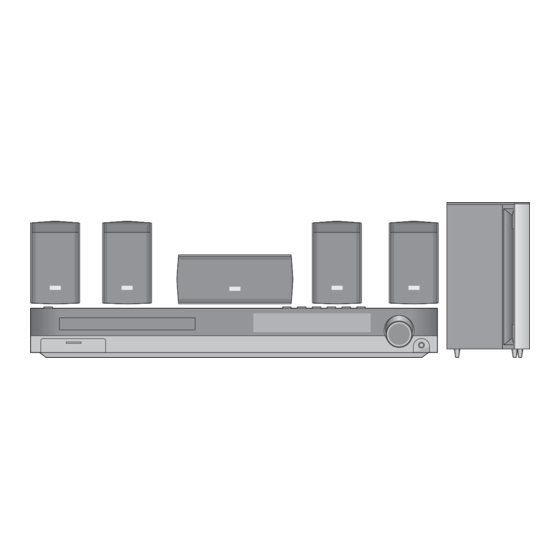
• Packing Accessory Section OPTIONAL PART 811 PLUG ASS'Y 1WAY(YELLOW) MICRO PHONE FILTER(CIRC) 824 ANTENNA LOOP(AM) 825 ANTENNA (FM) BATTERY INSTRUCTION ASSEMBLY REMOCON AC ADAPTOR PACKING, CASING PACKING, CASING 832 DISC... - Page 59 SECTION 5. SPEAKER SECTION 1. LHS-76SB • CENTER SPEAKER(LHS-76SBC)
- Page 60 4. LHS-96SB • FRONT/REAR SPEAKER(LHS-76SBS)
- Page 61 2. LHS-76IB • PASSIVE SUBWOOFER SPEAKER(LHS-76SBW) OPTIONAL PART...
Need help?
Do you have a question about the LH-T7652SB and is the answer not in the manual?
Questions and answers