
Related Manuals for LG LH-T6749


Summary of Contents for LG LH-T6749
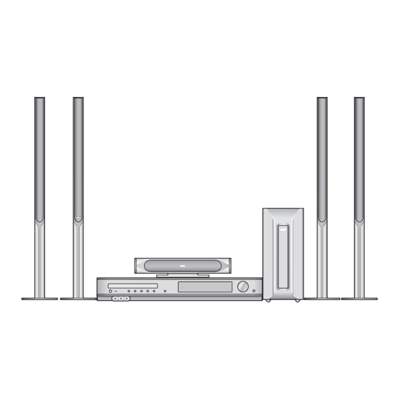
- Page 1 DVD/CD RECEIVER SERVICE MANUAL MODEL : LH-T6749(A)/ LHS-T6749C/LHS-T6749T/LHS-T6749W P/NO : 3829RDT050N NOVEMBER, 2006...
- Page 2 [CONTENTS] ❍ SECTION 1.GENERAL • SERVICING PRECAUTIONS ..........1-2 •...
-
Page 3: Section 1. General
SECTION 1. GENERAL ❏ SERVICING PRECAUTIONS NOTES REGARDING HANDLING OF THE PICK-UP 1. Notes for transport and storage 1) The pick-up should always be left in its conductive bag until immediately prior to use. 2) The pick-up should never be subjected to external pressure or impact. Storage in conductive bag Drop impact 2. -
Page 4: Notes Regarding Compact Disc Player Repairs
NOTES REGARDING COMPACT DISC PLAYER REPAIRS 1. Preparations 1) Compact disc players incorporate a great many ICs as well as the pick-up (laser diode). These components are sensitive to, and easily affected by, static electricity. If such static electricity is high voltage, components can be damaged, and for that reason components should be handled with care. - Page 5 ❏ ESD PRECAUTIONS Electrostatically Sensitive Devices (ESD) Some semiconductor (solid state) devices can be damaged easily by static electricity. Such components commonly are called Electrostatically Sensitive Devices (ESD). Examples of typical ESD devices are integrated circuits and some field-effect transistors and semiconductor chip components. The following techniques should be used to help reduce the incidence of component damage caused by static electricity.
- Page 6 ❏ SPECIFICATIONS - 1-5 -...
- Page 7 - 1-6 -...
-
Page 8: Section 2. Audio Part
SECTION 2. AUDIO PART ❏ ELECTRICAL TROUBLESHOOTING GUIDE 1. Power check flow INSERT POWER CORD. TURN ON CHECK POWER PLUG THE RED LED? AND POWER SUPPLY CIRCUIT . TURN POWER ON. IS POWER ON? CHECK POWER SUPPLY CIRCUIT . DOES INITIAL CHECK LASER CIRCUIT . - Page 9 2.AUDIO µ.COM CIRCUIT POWER ON Does AV 1/2, TV, AUDIO, Does CD/DVD OPTICAL IN, COAXIAL IN, FM87.5 appear at FLD? appear at FLD? Does it appear Does LOADING DVD Error at appear at FLD? FLD? Check Does no Disc or Connector(PN902)if Reconnet it.
- Page 10 3.FRONT CIRCUIT (1/2) - 2-3 -...
- Page 11 4.FRONT CIRCUIT (2/2) - 2-4 -...
-
Page 12: Section 3. Dvd Part
SECTION 3. DVD PART ❏ ELECTRICAL TROUBLESHOOTING GUIDE 1. Power check flow - 3-1 -... - Page 13 2. System operation flow Power On 1. 8032 initializes SERVO, DSP & RISC registers 2. Write RISC code to SDRAM 3. Reset RISC Show LOGO Tray Closed? Tray Close to Closed position SLED at Inner Side ? SLED Moves to Inner Positi on 1.
- Page 14 3. Test & debug flow TEST Check the AC Voltage Replace power PCBA or Power PCBA(110V or 220V) AC transformer. Switch on the Power PCBA Is the DC Voltage Repair or Replace Power PCBA outputs OK? (5V,1.8V,3.3V,8V,12V) Make sure the main PCBA don't short on VCCs and switch it on.
- Page 15 RESET or Power On. Check connection lines between FLASH Flash Memory operates & MT1389 and the FLASH access time Show LOGO? properly? whether is suitable or not. Check connection lines between SDRAM works properly? SDRAM & MT1389 and the SDRAM is damaged.
- Page 16 Does the SLED move Motor Driver STBY Check the connection line of to inner side when it is at Pin is High? STBY signal. outter position? Is FMSO DC Level higher Check the related circuit of than 1.4V? FMSO. SL+ and SL- output Check the amp circuit on motor properly? driver.
- Page 17 Check the laser power circuit Laser turns on when LD01 or LD02 output on MT1336 and connecting to reading disc? properly? power transistor. Collector voltage of Check the related circuit on power transistor is OK? laser power transistor Check cable connection between transistor ouput and pick-up head.
- Page 18 Proper signals on Check connections between Focus ON OK? A,B,C,D of MT1389 MT1389 and pick-up head. Check the FOSO connection on Check FEO signal MT1389 and motor driver. on MT1389 Check FOSO signal on MT1389 Check the related Normal TEO Signal on Track On OK? circuit on MT1389 MT1389?
- Page 19 Normal Audio output Audio PWM IC received Check connection between MT1379 when disc playback? correct data stream? & Audio PWM IC. Check the related Normal Audio PWM IC circuit of Audio PWM IC. out? Check Audio filter,amplify,mute circuit. Communications between Normal IR.VFD &...
-
Page 20: System 27Mhz Clock,Reset,Flash R/W Signal
❏ DETAILS AND WAVEFORMS ON SYSTEM TEST AND DEBUGGING 1. SYSTEM 27MHz CLOCK,RESET,FLASH R/W SIGNAL 1) MT1379 main clock is at 27MHz(X501) FIG 1-1 2) MT1336 reset is high active FIG 1-2 - 3-9 -... - Page 21 3) RS232 waveform during procedure(Downloading) FIG 1-3 4) Flash R/W enable signal during download(Downloading) FIG 1-4 - 3-10 -...
-
Page 22: Sdram Clock
2. SDRAM CLOCK 1) MT1379 main clock is at 27MHz(X501) FIG 2-1 3. TRAY OPEN/CLOSE SIGNAL FIG 3-1 - 3-11 -... -
Page 23: Sled Control Related Signal (No Disc Condition)
4. SLED CONTROL RELATED SIGNAL (NO DISC CONDITION) FIG 4-1 5. LENS CONTROL RELATED SIGNAL(NO DISC CONDITION) FIG 5-1 - 3-12 -... - Page 24 6. LASER POWER CONTROL RELATED SIGNAL (NO DISC CONDITION) FIG 6-1 7. DISC TYPE JUDGEMENT W VEFORM FIG 7-1 - 3-13 -...
- Page 25 FIG 7-2 (DVD) FIG 7-3 (CD) - 3-14 -...
- Page 26 FIG 7-4 (CD) 8. FOCUS ON W VEFORM FIG 8-1 (DVD) - 3-15 -...
- Page 27 FIG 8-2 (CD) 9. SPINDLE CONTROL W VEFORM (NO DISC CONDITION) FIG 9-1 - 3-16 -...
-
Page 28: Tracking Control Related Signal(System Checking)
10. TRACKING CONTROL RELATED SIGNAL(System checking) FIG 10-1 (DVD) FIG 10-2 (CD) - 3-17 -... -
Page 29: Mt1389 Video Output Waveform
11. MT1389 AUDIO OPTICAL AND COAXIAL INPUT (SPDIF) FIG 11-1 (DVD) 12. MT1389 VIDEO OUTPUT WAVEFORM 1)100% FIG 12-1 - 3-18 -... -
Page 30: Composite Video Signal
2) COMPOSITE VIDEO SIGNAL FIG 12-2 13. MT1389 AUDIO OUTPUT TO PWM IC ADAT0~3 FIG 13-1 - 3-19 -... - Page 31 14. AUDIO OUTPUT FROM PWM IC FIG 14-1 - 3-20 -...
- Page 32 ❏ BLOCK DIAGRAM 1. Overall Block Diagram CVBS - 3-21 -...
- Page 33 2. SERVO Block Diagram - 3-22 -...
-
Page 34: Mpeg & Memory Block Diagram
3. MPEG & MEMORY Block Diagram - 3-23 -... -
Page 35: Video & Audio Block Diagram
4. VIDEO & AUDIO Block Diagram - 3-24 -... - Page 36 ❏ BLOCK DIAGRAM...
-
Page 37: Front Schematic Diagram
❏ SCHEMATIC DIAGRAMS • FRONT SCHEMATIC DIAGRAM... - Page 38 • MICOM SCHEMATIC DIAGRAM 2-10...
-
Page 39: I//O Schematic Diagram
• I//O SCHEMATIC DIAGRAM 2-11 2-12... -
Page 40: Dsp Schematic Diagram
• DSP SCHEMATIC DIAGRAM 2-13 2-14... -
Page 41: Amp Schematic Diagram
• AMP SCHEMATIC DIAGRAM 2-15 2-16... - Page 42 • SMPS-WIDE SCHEMATIC DIAGRAM 2-17 2-18...
-
Page 43: Power Schematic Diagram
• POWER SCHEMATIC DIAGRAM 2-19 2-20... - Page 44 ❏ PRINTED CIRCUIT DIAGRAMS • MAIN P.C. BOARD (COMPONENT SIDE) 2-23 2-24...
- Page 45 • MAIN P.C. BOARD (SOLDER SIDE) 2-25 2-26...
- Page 46 ❏ WIRING DIAGRAMS 2-21 2-22...
- Page 47 • FRONT P.C.BOARD (SOLDER SIDE) • FRONT P.C.BOARD (COMPONENT SIDE) 2-27 2-28...
-
Page 48: Power P.c.board
• POWER P.C.BOARD 2-29 2-30... - Page 49 2-31 2-32...
- Page 50 ❏ DVD PART SCHEMATIC DIAGRAMS • MPEG SCHEMATIC DIAGRAM 3-25 3-26...
-
Page 51: Servo Schematic Diagram
• SERVO SCHEMATIC DIAGRAM 3-27 3-28... -
Page 52: Section 4. Exploded Views
SECTION 4. EXPLODED VIEWS ❏ CABINET AND MAIN FRAME SECTION NOTE) Refer to “SECTION 6 REPLACEMENT PARTS LIST” in order to look for the part number of each part. A43A... -
Page 53: Deck Mechanism Exploded View
• DECK MECHANISM EXPLODED VIEW 015B 015A 012A 012A 035A... -
Page 54: Section 5. Speaker Part
SECTION 5. SPEAKER PART ❏ MODEL: LHS-T6749W - 5-1 -... - Page 55 ❏ MODEL: LHS-T6749C - 5-2 -...
- Page 56 ❏ MODEL: LHS-T6749T A80B A80A - 5-3 -...
- Page 57 - 5-4 -...
Need help?
Do you have a question about the LH-T6749 and is the answer not in the manual?
Questions and answers