Samsung RS2511 Series Service Manual

Samsung RS2511 Series Service Manual

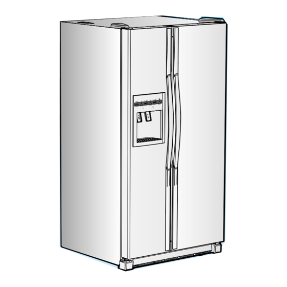
Side-by-side refrigerator
Hide thumbs Also See for RS2511 Series:
Table of Contents

Advertisement

SAMSUNG Home Appliance Service
SIDE-BY-SIDE REFRIGERATOR
MODEL:
RS2511
RS2611
RS2630W/XAA
RS2531
RS2631
RS2521
RS2621
RS2630SW

Advertisement

Table of Contents
loading

Summary of Contents for Samsung RS2511 Series

  • Page 1 SAMSUNG Home Appliance Service SIDE-BY-SIDE REFRIGERATOR MODEL: RS2511 RS2611 RS2630W/XAA RS2531 RS2631 RS2521 RS2621 RS2630SW...
  • Page 2: Important Safety Notice

    The manufacturer or dealer cannot be responsible for the interpretation of this information. SAMSUNG ELECTRONICS AMERICA, INC. Technical Service Guide Copyright ⓒ2004 All rights reserved. This service guide may not be reproduced in whole or in part in any form without written permission from the SAMSUNG ELECTRONICS Company.
  • Page 3: Table Of Contents

    Contents 1. Safety instruction on services ∙∙∙∙∙∙∙∙∙∙∙∙∙∙∙∙∙∙∙∙∙∙∙∙∙∙∙∙∙∙ 2. Warranty information ∙∙∙∙∙∙∙∙∙∙∙∙∙∙∙∙∙∙∙∙∙∙∙∙∙∙∙∙∙∙∙∙∙∙∙ 3. Mechanical Disassembly ∙∙∙∙∙∙∙∙∙∙∙∙∙∙∙∙∙∙∙∙∙∙∙∙∙∙∙∙∙∙∙∙ 4. Circuit Diagram ∙∙∙∙∙∙∙∙∙∙∙∙∙∙∙∙∙∙∙∙∙∙∙∙∙∙∙∙∙∙∙∙∙∙∙∙∙∙ 5. Operation Principles By Parts Of Circuit ∙∙∙∙∙∙∙∙∙∙∙∙∙∙∙∙∙∙∙∙∙∙∙∙ 6.Introduction ∙∙∙∙∙∙∙∙∙∙∙∙∙∙∙∙∙∙∙∙∙∙∙∙∙∙∙∙∙∙∙∙∙ 7. Installation 8. Nomenclature 9. Specifications 10. Interior Views and Dimensions 11.
  • Page 4: Safety Instruction On Services

    1. Safety Instructions on Service ●Unplug the refrigerator before making any repair or any replacement. � Avoid the electric shock. ●Use the rated components on the replacement. � Check the correct model number, rated voltage, rated current, operating temperature and so ●On repair, be sure that the wires such as harness are bundled tightly and are not exposed by water.
  • Page 5: Warranty Information

    SAMSUNG or SAMSUNG's authorized service center. SAMSUNG will repair or replace any part found to be defective, at our option and at no charge as stipulated herein, with new or reconditioned parts during the limited warranty period specified above. All replaced parts and products become the property of SAMSUNG and must be returned to SAMSUNG.
  • Page 6: Table Of Contents

    3. Mechanical Disassembly 3-1) Refrigerator Disassembly Control Panel ∙∙∙∙∙∙∙∙∙∙∙∙∙∙∙∙∙∙∙∙∙∙∙∙∙∙∙∙∙∙∙∙∙∙∙∙∙∙∙∙ Door Handle ∙∙∙∙∙∙∙∙∙∙∙∙∙∙∙∙∙∙∙∙∙∙∙∙∙∙∙∙∙∙∙∙∙∙∙∙∙∙∙∙∙ Door Gasket ∙∙∙∙∙∙∙∙∙∙∙∙∙∙∙∙∙∙∙∙∙∙∙∙∙∙∙∙∙∙∙∙∙∙∙∙∙∙∙∙∙ Refrigerator Door Light Switch ∙∙∙∙∙∙∙∙∙∙∙∙∙∙∙∙∙∙∙∙∙∙∙∙∙∙∙∙∙∙∙ Refrigerator Light ∙∙∙∙∙∙∙∙∙∙∙∙∙∙∙∙∙∙∙∙∙∙∙∙∙∙∙∙∙∙∙∙∙∙∙∙∙∙ Tempered Glass Shelf ∙∙∙∙∙∙∙∙∙∙∙∙∙∙∙∙∙∙∙∙∙∙∙∙∙∙∙∙∙∙∙∙∙∙∙ Plastic Drawers in Refrigerator ∙∙∙∙∙∙∙∙∙∙∙∙∙∙∙∙∙∙∙∙∙∙∙∙∙∙∙∙∙∙ Gallon Door Bin ∙∙∙∙∙∙∙∙∙∙∙∙∙∙∙∙∙∙∙∙∙∙∙∙∙∙∙∙∙∙∙∙∙∙∙∙∙∙∙ Water Filter ∙∙∙∙∙∙∙∙∙∙∙∙∙∙∙∙∙∙∙∙∙∙∙∙∙∙∙∙∙∙∙∙∙∙∙∙∙∙∙∙∙ Damper in the Refrigerator ∙∙∙∙∙∙∙∙∙∙∙∙∙∙∙∙∙∙∙∙∙∙∙∙∙∙∙∙∙∙∙∙...
  • Page 7: Control Panel

    3. Mechanical Disassembly 3-1) Refrigerator Disassembly Control Panel Door Gasket The door gasket is a molded gasket set into a 1. Insert a flat-blade screwdriver on the slot as shown, channel located in the door liner. and unlock the tabs. 1.
  • Page 8: Refrigerator Light

    Mechanical Disassembly Refrigerator Light The refrigerator light is located in the upper portion of refrigerator. 1. Pull the tip on the cover. Gallon Door Bin The door bins allow storage of perishable items. 1. Push the bin up and slide it out. Tempered Glass Shelf These shelves allow the storage of larger items and pull out for easy access.
  • Page 9: Damper In The Refrigerator

    Mechanical Disassembly Damper in the Refrigerator Refrigerator Thermistor 1. Pull out the screw cap and remove the screw. The refrigerator thermistor is located inside of the 2. Remove the lamp cover by unlocking the tabs upper light cover of the refrigerator. and pulling the cover down.
  • Page 10: Door Bin In Freezer

    Mechanical Disassembly 3-2) Freezer Disassembly Door Bin in Freezer The door bins allow storage of perishable items. 1. Push the bin up and slide it out. Freezer Shelf The shelves slide out for easy access for frozen items. 1. Slide the shelf out until it reaches its stop. 2.
  • Page 11: Auger Motor Case

    Mechanical Disassembly top of the liner, and slide the ice maker in. Ice Dispenser & Ice Maker 5. Tighten the screws (2) of the ice maker support. The ice dispenser is located in the upper portion of the freezer. This assembly stores ice made by the icemaker and dispenses ice.
  • Page 12: Freezer Light

    Mechanical Disassembly Freezer Light Evaporator Cover in Freezer The freezer light is located in the bottom of the 1. Remove screw (6). auger motor case. The light is covered by an opaque 2. Remove the assy cover multi fre. cover. 3.
  • Page 13: Evaporator In Freezer

    Mechanical Disassembly Evaporator in Freezer Evaporator is located in the bottom of freezer to produce cold air driven across the evaporator coils. 1. Take off the ductwork in Freezer. 2. Disconnect the wire connector (Heater, Bimental, and Thermistor). 3. Desolder the inlet and outlet tubes. 4.
  • Page 14: Mechanical Disassembly

    Mechanical Disassembly 3-3) Machine Compartment Disassembly Machine Compartment & & Electric Box 1. Disconnect the power cord of the refrigerator. 2. Remove the fixed screws (6) of compressor cover. Condenser Fan 3. Slide up and take off the compressor cover to The condenser Fan is located in the middle of see the machine compartment.
  • Page 15: Circuit Diagram

    4. CIRCUIT DIAGRAM...
  • Page 16: Operation Principles By Parts Of Circuit

    5. OPERATION PRINCIPLES BY PARTS OF CIRCUIT 5-1) POWER Terminal Oscillation Frequency ● Vcc(DC 5V) MICOM POWER AND SENSORS << BLDC BLDC MOTOR POWER(NOT USE) +12V(DC 12V) RELAY,PANEL POWER When turned on, rectified AC voltage which is stepped down on 2nd transformer flows between ① and ③ at about AC 15V, goes through the diode D101 and D104 is changed to DC, and provide constant 12V.
  • Page 17 OPERATION PRINCIPLES BY PARTS OF CIRCUIT 5-3) RESET CIRCUIT RESET Circuit allows the whole program to go back to the initial setting by initializing parts such as the RAM in MICOM with the power supply into MICOM or with an instant power failure. Upon the power supply, the reset terminal voltage becomes "LOW"...
  • Page 18 OPERATION PRINCIPLES BY PARTS OF CIRCUIT 5-5) DOOR SWITCH DETECTON CIRCUIT 1) If R-Door is opened, the contact point of the door switch (4-3) becomes open, and the current of PCB line comes through R404 and R405 and provides 5 volt which is recognized as door is opened, and turn off the fan at different load.
  • Page 19 OPERATION PRINCIPLES BY PARTS OF CIRCUIT 5-6) TEMP SENSING CIRCUIT 1) Sensor uses a thermistor which has a temp coefficient of negative resistance and controls resistance. When the heat goes up, the resistance gets down and vice versa. R302, 4, 6, 9 and C301~C303, C305 are parts for noise prevention but they are not related to temp sensing characteristics.
  • Page 20 OPERATION PRINCIPLES BY PARTS OF CIRCUIT � Temp to Resistance of Sensor & MICOM PORT Voltage Sensor CHIP : PX41C Standard Temp. Voltage(V) Temp. Voltage(V) Temp. Voltage(V) Temp. Voltage(V) Resistance(㏀) Resistance(㏀) Resistance(㏀) Resistance(㏀) -50 °F/ - 45. 6 °C 4.694 -19°F/-28.3°C 3.773 12°F/-11.1°C...
  • Page 21 OPERATION PRINCIPLES BY PARTS OF CIRCUIT 5-7) DAMPER CIRCUIT 1) The temperature of R-room is controlled by opening and closing of damper with stepping motor, supplying & blocking cold air. 2) TA7774P (IC07) operates the damper. TA7774P is the driver IC only for step motor. If the regular signal is provided to TA7774P from Micom, send combined signal to Quad-Polar step motor to rotate on certain direction.
  • Page 22 OPERATION PRINCIPLES BY PARTS OF CIRCUIT 2) DISPLAY OPERATION Like the signal diagram below, Micom sends “ high ” signal through MICOM 6 terminals of NO #1→ 2 → 3 → 4 → 5 → 6 for 2ms every 12ms. This signal goes to output terminal via input terminal of IC5 (KID65783AP or TD62783AP).
  • Page 23 OPERATION PRINCIPLES BY PARTS OF CIRCUIT 5-9) Load Control Circuit 1) Main PCB processes most of the load control for electronic refrigerators. 2) Compressor, F-Room, defrost heater, and other functions are controlled with relay. 3) For example, to operate compressor, MICOM 29 pin outputs high (5V) signal which goes into IC3 Pin #4. The IC3 pin NO 4 plays the same role as the base of NPN TR.
  • Page 24 OPERATION PRINCIPLES BY PARTS OF CIRCUIT 5-10) ICE MAKER OPERATION CIRCUIT 1) The ice maker circuit above is to control the ice maker kit installed on the F room. 2) This circuit is the hardware to control ejection and horizontal positioning, ice making temperature detection and full icing detection.
  • Page 25 OPERATION PRINCIPLES BY PARTS OF CIRCUIT 5-11) OPTION Circuit This circuit operates with the initial power on, uses DIODE (1N4148) or JUMPER WIRE. To modify option circuit, Power must be turned off before modification and turned on after the modification. Refer to the table below, the default factory values are highly recommended unless exceptional cases.
  • Page 26 Appendix Ⅰ Ⅰ (Reference for circuit diagnostics) Ref.1) Measure Load Terminals � Turn off Power, disassemble Housing connected to MAIN PCB CN70,71,72 and measure followings LOAD TERMINALS PCB CASE VALUE DEFECTS OTHERS 0Ϊ THERMAL FUSE, HEATER, WIRE SHORT THERMAL 1) DEFROST HEATER CN71 ⑪...
  • Page 27 Appendix Ⅰ Ⅰ (Reference for circuit diagnostics) � Turn on Power and check status of Relay & Driving Circuit by checking followings according to load operation. LOAD RELAY TERMINALS VALUE WHEN IT IS DIFFERENT FROM MEASURED VALUE SUPPLY RY76 /RY75 CN71⑪�⑨...
  • Page 28 Appendix Ⅰ Ⅰ (Reference for circuit diagnostics) Ref. 3) SERVICE PARTS LIST FOR CIRCUIT ITEM SPEC CODE NO OTHERS AD ELECTRONIC RS2 * 11 DA41-00219A PBAMAIN AD ELECTRONIC RS2 * 21 DA41-00219B AD ELECTRONIC RS2 * 3 * DA41-00219C RS2 * 11 DA41-00218A RS2 * 21 DA41-00218B...
  • Page 29: Introduction

    1. INTRODUCTION A newly developed SAMSUNG side by side refrigerator in 2004 has the following ● ● characteristics. 1) Twin X AirFlow ∙Cool air circulates through side vents on every shelf level. This provides even distribution of cooling inside cabinets to keep your food fresh longer.
  • Page 30: Installation

    2. INSTALLATION 1) To protect refrigerator in movement Use padded hand truck as shown. If entrance width is less than 39 〃 , remove doors prior to installation and reattach doors according to procedure below. 2) Remove all protective tape and pad in refrigerators. Connect water lines and power cord.
  • Page 31: Nomenclature

    Buyer Code: XAA, XAC, CUR COLOR ; WW-WHITE(PCM) SH-STAINLESS PLATINUM SW-SNOW WHITE OPTION ; 30-BEST BUY 11,21,31 ; SAMSUNG Capacity ; 25,26 cu. ft Family ; S - SIDE BY SIDE (SBS) Product ; R-SAMSUNG REFRIGERATOR B-OEM REFRIGERATOR Label Location...
  • Page 32: Specifications

    4. Specifications ELECTRICAL SPECIFICATIONS Freezer Refrigerator Defrost Control From 6 to 11 hrs Defrost Thermistor(502AT) 59℉(off) Electrical Rating AC115V 60Hz 11.6 Amps Maximum Current Leakage 0.25 mA Maximum Ground Path Resistance 0.1Ohm Energy Consumption kWh/mo. Bimetal 104℉(on)/140℉(off) NO LOAD PERFORMANCE Ambient Temperature 70℉...
  • Page 33: Interior Views And Dimensions

    5. Interior Views and Dimensions 5-1) Shelves and Bins Freezer RS2511 ** / RS2611 ** RS2521 ** / RS2621 ** RS2531 ** / RS2631 ** Xtra Space Ice Maker Door Bin Light Ice Chute Wire Shelf Drawers Front Leg Cover...
  • Page 34 Interior Views and Dimensions 5-2) Dimensions of Refrigerator(RS26 ** ) (Inches) 29.5 35.6 32.2 32.1...
  • Page 35 Interior Views and Dimensions 5-3) Dimensions of Refrigerator(RS25 ** ) (Inches) 29.5 34.9 31.9 32.1...
  • Page 36: Refrigeration Cycle And Cool Air Circulation Route

    6. Refrigeration Cycle and Cool Air Circulation Route 6-1) Refrigerant Route in Refrigeration cycle Compressor →Condenser → Hot Pipe → Dryer → Capillary Tube → Evaporator → Suction Pipe → Compressor Accumulator Evaporator Dryer Hot Pipe Suction Pipe Condenser Capillary Tube Muffler Compressor Hot Pipe...
  • Page 37 Refrigeration Cycle and Cool Air Circulation Route 6-2) Cool Air Circulation Freezer Refrigerator...
  • Page 38: Function & How- To-Use By Products

    7. Function & How- to-use By Products 7-1) DISPLAY DESIGN RS2630SW/XAA (for Best Buy) RS2531 ** /RS2631 ** RS2521 ** /RS2621 ** RS2511 ** /RS2611 **...
  • Page 39 7. Function & How- to-use By Products 7-2) TEMP CONTROL 1) Freezer Temp Setting 1-1) With the initial power on, Freezer will be set at MID (-4°F/-20°C) and Refrigerator will be set at MID (37°F/3°C) automatically. At this time, the number of LEDs (1 ~ 5) lighting up on the display panel means intensity (MIN ~ MAX) of room control temperature (6.8 ~ -13°F/-14 ~ -25 °C) and as the intensity gets increased, the number of LEDs increases and the set temperature become lowered.
  • Page 40 Function & How- to-use By Products 7-4) CHILD LOCK (on some models) When Child Lock Button on the front panel is pressed for a certain period (3sec.), Child Lock LED gets on and all other buttons on the front panel except for Child Lock Button do not operate. Also, Ice/Water Dispensers do not work.
  • Page 41 Function & How- to-use By Products 7-6) FAN MOTOR DELAY (COMPRESSOR ROOM) Among the functions depending on Peripheral Temp, Comp Cooling Fan (Comp Room Fan) is controlled according to Peripheral Temp as follows. Therefore, make sure to check the contents to refer to during A/S because Cooling Fan can operate or not according to conditions during Comp operation.
  • Page 42 Function & How- to-use By Products 2) Water Supply It is the movement to supply water on the ICE-TRAY by using the SOLENOID VALVE after the completion of the ejection (Ejection after the completion of the normal ice making or that by the test movement) Considering cases with low hydraulic pressure, when it is recognized as No Water Supply, the Water Supply will be attempted for 4 times.
  • Page 43 Function & How- to-use By Products Assumption of the ambient temp of higher than 64.4 °F/ 18 °C Low water pressure 5s 1.5s 1.5s 1s Initial 2hr standby 90+(5)min 70+(5)min 70+(5)min No Water Supply No Water Supply No Water Supply Power On High water pressure 55+(5)min...
  • Page 44 Function & How- to-use By Products 4) Ice Ejection It is the movement to separate the ice cubes from the ICE-TRAY after the completion of ice making, which is conducted by the following steps. Check the changes in status and time for the horizontal S/W (if it is used) and the ice level check S/W in parallel and then operate Ejection.
  • Page 45 Function & How- to-use By Products 4-3) Ejection Movement TIMING CHART Max TRAY twist Standby(2sec) Restorating to Completion Initial Ejecting horizontal status horizontal status horizontal status Ice Level S/W Eject Motor rotates clockwise Eject Motor rotates counter clockwise 5) Ice Test It is necessary for the forced operation for the purpose of the operation test, A/S, and cleaning, and when pressing the ICE TEST S/W for a certain time period (more than 1.5 sec.), it goes into operation.
  • Page 46 Function & How- to-use By Products 7-9) ALARM 1) Button TOUCH 1-1) When selecting each button in the CONTROL PANEL, the verification sound (Ding Dong) of input shall be heard. 1-2) In the case of pressing more than two KEYS at the same time or pressing the wrong button, the sound shall not be heard.
  • Page 47 Press for 8 sec RS2521 ** /RS2621 ** Press for 8 sec RS2511 ** /RS2611 ** Press for 8 sec 1) Forced Operation 1-1) When pressing TEST KEY once in TEST MODE, Forced Operation shall be selected and with BEEP sound, alarm will be operated.
  • Page 48 Function & How- to-use By Products 2) Forced Defrost 2-1) When pressing TEST KET twice in TEST MODE, Freezer defrost will operate and BEEP sound alarm shall be heard. 2-2) BEEP sound alarm shall operate until the completion of HEATING and pause. 2-3) With the selection of forced Freezer defrost, it will operate regardless of the point of normal Heater On and complete defrost while comparing the temp of the point of HEATER OFF.
  • Page 49 Function & How- to-use By Products RS2511 ** /RS2611 ** Press for 8 sec If the temp of Freezer/Refrigerator increases more than (149 °F/ 65 °C) in Exhibition Mode, it will restore to normal operation mode. Contents of operation in Exhibition Mode DISPLAY, FAN MOTOR, and DISPENSER will operate normally except for Comp.
  • Page 50 Function & How- to-use By Products 1) Self-diagnosis with initial POWER ON 1-1) With POWER ON, it shall diagnose the status of temp SENSOR in a minute in MICOM internally for itself. 1-2) If inferior sensor is found after self-diagnosis, corresponding DISPLAY LED will be all off at the interval of 0.5 sec.
  • Page 51 ② Press after ① RS2531 ** /RS2631 ** ① Press for 6 sec ② Press after ① RS2521 ** /RS2621 ** ① Press for 6 sec ② Press after ① RS2511 ** /RS2611 ** ① Press for 6 sec ② Press after ①...
  • Page 52 Function & How- to-use By Products � Details by LED ON locations indicating load status ITEMS DISPLAY LED PROBLEM Refrigerator "MIN" (1’st) LED ON whenDamper is open Damper Condition for Refrigerator "MID" (3’rd) LED ON when Ambient temp is over (95°F/35 °C) over load Condition for Refrigerator "MAX"...
  • Page 53 Function & How- to-use By Products RS2521 ** /RS2621 ** Press for 12 sec RS2511 ** /RS2611 ** Press for 12 sec 1) For example,,if you want to shift the Refrigerator STD temp by (34.7°F/1.5 °C), proceed the following. It is to shift the standard temperature.The F-Room standard temp is 3 °C(MID).When it is shifted (34.7°F/1.5 °C) by using the option,the standard temp will be set to (40.1°F/4.5 °C) i.e.when the temp option is changed, it...
  • Page 54 Function & How- to-use By Products 1-3) If you set "10"as shown in the Freezer option table below after setting "1"to the OPTION CATEGORY,the Refrigerator standard temp will be lowered by -5.4°F(Refer to the Refrigerator Temp Option Table) :In 20 seconds after completion of adjustment,the MICOM will store the set value to the EEPROM and it will revert to the normal display and the option setting mode will be cancelled.
  • Page 55 Function & How- to-use By Products APP .EX) TO INCREASE REFRIGERATOR STANDARD TEMP BY (2.7°F/1.5°C) RS2630SW/XAA (for Best Buy) V1 V2 V3 V4 I1 I2 I3 I4 I5 Value- Value+ Item+ Item- Option Setting Option Cate (10: 2.7°F/1.5°C) (1:Refrigerator Standard Temp) RS2531 ** /RS2631 ** V1 V2 V3 V4 I1 I2 I3 I4 I5...
  • Page 56 Function & How- to-use By Products APP .EX)TO LOWER FREEZER STANDARD TEMP BY (-5.4°F/-3°C). RS2511 ** /RS2611 ** Value- Value+ Item+ Item- V1 V2 V3 V4 I1 I2 I3 I4 I5 Dispenser LED Option Setting Option CATE. (6:(-5.4°F/-3°C)) (0:Freezer Standard Temp) APP .EX) TO INCREASE REFRIGERATOR STANDARD TEMP BY (2.7°F/1.5°C)
  • Page 57 Function & How- to-use By Products 7-16) OPTION TABLE Note) With the Freezer button and the Lighting button, additional options can be set. But, those are relevant not to the A/S but to the ref.control function. So, those options are skipped. (Do not change any other options except the above options.) 1) FREEZER TEMP SHIFT TABLE(○: RELEVANT LED OFF, ●: RELEVANT LED ON) SET ITEM...
  • Page 58: Diagnostics

    8. Diagnostics 8-1) When power is not supplied Pre-Check 1. Check if power is supplied at Concent and Power Cord is connected properly before repair 2. Check by referring to the followings. Start Is Power of primery DC -TRANS applied? Check assembly of wires and do repairing Is Power of secondary...
  • Page 59 Diagnostics 8-2) When there is a trouble with Self Diagnosis 1) Ambient Sensor trouble => (applied to Ambient Sensor Temp type) Start Is Ambient Sensor normal? (PANEL PCB) Change Ambient Sensor Is MAIN PCB (CN31) insertion normal? Connector contact trouble /re-insertion Is the connection wire between MAIN PCB connector(CN32) and Temp Sensor...
  • Page 60 Diagnostics 3) Freezer Temp Sensor trouble Start Is Freezer Temp Sensor normal? Change Temp Sensor Is the insertion of MAIN PCB connector(CN30) normal? Connector contact trouble /re-insertion Is the connection between MAIN PCB connector(CN30) and Temp Sensor(yellow) normal? Short between connector Sensors Is MICOM Pin#57 input voltage normal? Check soldering fault,short,...
  • Page 61 Diagnostics 8-3) When COMP does not operat Pre-Check 1. If it doesnotpass5 min after a desired Temp reached, COMP does not operate. 2. During Defrost, COMP does not operate. 3. With the disconnected Freezer Sensor or Refrigerator Sensor, COMP does not operate because MAIN PCB picks up theTemp as a desired level.
  • Page 62 Diagnostics 8-4) When FAN & DAMPER does not operate Note "Check out the F-FAN with the Forced Operation selected" 1. Freezer FAN, Refrigerator DAMPER and COMP COOLING FAN remains off while COMP is turned off. 2. When Comp is ON, Damper does not always remain ON (including Forced Operaation) and when Refrigerator temp reaches to set temp, Damper remains OFF.
  • Page 63 Diagnostics 2) When Refrigerator DAMPER does not operate Start Is DAMPER in operating conditions? Forced Operation/ Temp Increase Does DAMPER operates with DOOR S/W pressed? DAMPER is normal MICOM voltage DOOR OPEN : 5V Is DOOR S/W normal? DOOR CLOSE : 0V Change DOOR S/W Is voltage of MICOM #50 normal?
  • Page 64 Diagnostics 3) When Comp Cooling Fan does not operate Start Is COMP operating? Operate Forced Operation Is it COMP COOLING FAN ON condition? Stand by for FAN ON condition Confirm FAN operating condition Ambient Temp Range Load Operation Status Comp Fan operates immediately Higher than (64.4 °F/18 °C) upon COMP ON Comp Fan...
  • Page 65 Diagnostics 8-5) When Defrost does not operate Pre-Check 1. With a shorted-out Defrost Sensor, the fridge operates normally excepting Defrost(The fault can be picked up with self-diagnosis, POWER ON/OFF). 2. There will be Heating trouble with a shorted-out Temp FUSE, which contributes to Defrost by natural Temp increase resulting in a Temp Control problem stemmed from the increased COMP OFF time.
  • Page 66 Diagnostics Does the Function return to the normal after Heating ? Normal Is each concerned Defrost Sensor Temp higher than the terminated Temp? Concerned Sensor Change concerned Sensor resistance measurement (Appendix TABLE) Is the input voltage of MICOM #9 higher than the voltage upon the terminated Temp? Change Temp pick-up part, Concerned Sensor...
  • Page 67 Diagnostics 8-6) When Alarm Sound continues without stop Note 1. When Door gets open, Door Open alarm ("Ding Dong") goes off in 2 minutes with Door opened.When Door remains open after this, the alarm goes off every minute. 2. When Door Switch is not pressed well, MICOM considers it as opened and alarming sound goes off. Room Lamp becomes OFF in 10 minutessince it detectsDoor Open (based on R600a).In this case, even though Door gets opened, Room Lamp does not comes ON.
  • Page 68 Diagnostics Note 1. "Beep-Beep" sounds do not go off except Forced Operation & Forced Defrost. 2. It is checckableatPanel PCB when Forced Operation or Forced Defrost is selected, so when error occurs, check it andcorrect theerror. 3) When PANEL PCB doesn’t light up Start Is MAIN PCB 12V normal? (REG101)
  • Page 69 Diagnostics 8-7) When Room Lamp does not light up Note 1. Because Room Lamp is basically controled with Door Switch, PCB does not control it. 1) When Freezer/Refrigerator Lamps do not light up Start Is DOOR OPEN? DOOR OPEN Is DOOR SWITCH normal? Change DOOR SWITCH Is Room LAMP(R,F) normal?
  • Page 70 Diagnostics 8-8) Dispenser Lamp Malfunction Note 1. Long term LED Short when exchanging may result in the malfunction of PCB since Dispenser Lamp is high brightness LED. 2. When changing the PCB, the power must be turned off. Start ▶ CHECK METHOD Is ice &...
  • Page 71 Diagnostics 8-9) When Water Valve Does Not Operate Pre-Check 1. While disassembling, make sure to cut off water since the water valve is directly connected with water. 2.Makesure toavoidthe electricshock while disassembling because one end of wire is applied with power. 3.Check operation of water valve only after the water switch is pressed Check Water Valve Operation...
  • Page 72 Diagnostics 8-10) When Crush (Crushed Ice ) & Cube (Cubed Ice) does not operate well Start Operating condition is F-Room Door closing condition. Does Ice come out when extracting Ice? Is ice in Ice Box? Is Ice Stop selected in Ice Selection? ①...
  • Page 73 Kwangju-City, Korea, 506-253 TEL : 82-62-950-6810, 6811 FAX : 82-62-950-6829 - This Service Manual is a property of Samsung Electronics Co., Ltd. Any unauthorized use of Manual can be punished under applicable International and/or domestic law. - © Samsung Electronics Co., Ltd.

Table of Contents