Table of Contents
Advertisement
Quick Links
Advertisement
Table of Contents

Related Manuals for Supero Supero X8DTU-6F+


Summary of Contents for Supero Supero X8DTU-6F+
- Page 1 X8DTU-6F+ X8DTU-6TF+ X8DTU-6F+-LR X8DTU-6TF+-LR USER’S MANUAL Revision 1.0a...
- Page 2 This product, including software and docu- mentation, is the property of Supermicro and/or its licensors, and is supplied only under a license. Any use or reproduction of this product is not allowed, except as expressly permitted by the terms of said license.
-
Page 3: About This Motherboard
5500/5600 Series processors built in, the X8DTU-6F+/X8DTU-6TF+/X8DTU-6(T) F+-LR motherboard substantially enhances system performance in a small form- factor package. Please refer to our website (http://www.supermicro.com/products/) for updates on supported processors. This product is intended to be installed and serviced by professional technicians. -
Page 4: Conventions Used In The Manual
X8DTU-6F+/X8DTU-6TF+/X8DTU-6(T)F+-LR Motherboard User’s Manual Conventions Used in the Manual Special attention should be given to the following symbols for proper installation and to prevent damage done to the components or injury to yourself: Danger/Caution: Instructions to be strictly followed to prevent catastrophic system failure or to avoid bodily injury Warning: Important information given to ensure proper system installation or to prevent damage to the components... - Page 5 Super Micro Computer, Inc. 980 Rock Ave. San Jose, CA 95131 U.S.A. Tel: +1 (408) 503-8000 Fax: +1 (408) 503-8008 Email: marketing@supermicro.com (General Information) support@supermicro.com (Technical Support) Website: www.supermicro.com Europe Address: Super Micro Computer B.V. Het Sterrenbeeld 28, 5215 ML...
-
Page 6: Table Of Contents
X8DTU-6F+/X8DTU-6TF+/X8DTU-6(T)F+-LR Motherboard User’s Manual Table of Contents Preface Chapter 1 Quick Installation Guide Installing the CPU ................... 1-1 Installing the Passive CPU Heatsink .............. 1-1 Installing the Memory Modules ............... 1-2 Installing the I/O Shield ................... 1-2 Installing the Motherboard ................1-3 Connecting the Power Supply................. - Page 7 Table of Contents Back Panel I/O Port Locations and Defi nitions ........... 3-15 ATX PS/2 Keyboard and PS/2 Mouse Ports ..........3-16 Universal Serial Bus (USB) ..............3-17 Serial Ports ....................3-18 Video Connector ..................3-18 Gigabit Ethernet Ports ................3-19 10Gb TLAN Ports and SFP+ Devices (X8DTU-6TF+) ......
- Page 8 X8DTU-6F+/X8DTU-6TF+/X8DTU-6(T)F+-LR Motherboard User’s Manual Onboard LED Indicators ................3-38 GLAN 1/2 LEDs ..................3-38 IPMI Dedicated LAN LEDs ..............3-38 10Gb_LAN LED (X8DTU-6TF+) ............... 3-39 Onboard Power LED ................3-39 Rear UID LED ..................3-40 BMC Heartbeat LED ................3-40 SAS Activity &...
-
Page 9: Chapter 1 Quick Installation Guide
Chapter 1: Quick Installation Guide Chapter 1 Quick Installation Guide Installing the CPU A. Press the socket clip down to unlock B. Align the CPU key with the socket it. Gently lift the socket clip to open the key. load plate. C. -
Page 10: Installing The Memory Modules
X8DTU-6F+/X8DTU-6TF+/X8DTU-6(T)F+-LR User’s Manual Installing the Memory Modules A. Align the key on the DIMM module C. Press the notches on the ends of against that of the DIMM socket. the DIMM module inwards to lock it. B. Insert the DIMM module straight down to the DIMM socket. -
Page 11: Installing The Motherboard
Chapter 1: Quick Installation Guide Installing the Motherboard X8DTU-6F+ Connecting the Power Supply X8DTU-6F+... -
Page 12: Installing Internal Peripherals
X8DTU-6F+/X8DTU-6TF+/X8DTU-6(T)F+-LR User’s Manual Installing Internal Peripherals SATA / SAS Drives Installing External Peripherals IPMI LAN Mouse USB 0/1 VGA Port LAN 1/2 Ports TLAN 1/2 Ports UID Serial Port Keyboard (COM1) Switch... -
Page 13: Chapter 2 Overview
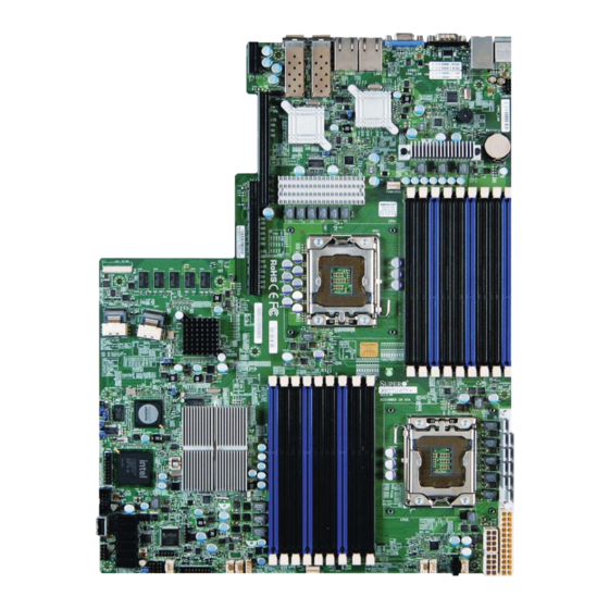
Checklist Congratulations on purchasing your computer motherboard from an acknowledged leader in the industry. Supermicro boards are designed with the utmost attention to detail to provide you with the highest standards in quality and performance. Please check that the following items have all been included with your motherboard. - Page 14 X8DTU-6F+/X8DTU-6TF+/X8DTU-6(T)F+-LR User’s Manual Motherboard Image Note: All graphics shown in this manual were based upon the latest PCB Revision available at the time of publishing of the manual. The motherboard you've received may or may not look exactly the same as the graphics shown in this manual.
- Page 15 I-SATA5 Notes • TLAN (10 Gb LAN) Ports 1 &2 are available on the X8DTU-6TF+ only. • IPMI 2.0 support is available on the motherboard. For more information, refer to the user guide posted on our website @ http://www.supermicro.com/support/ manuals/...
- Page 16 X8DTU-6F+/X8DTU-6TF+/X8DTU-6(T)F+-LR User’s Manual LED7 LAN2 LAN1 USB0/1 COM1 IPMI_LAN Intel 82576 LAN 1/2 Intel 82599 CTRL 10 Gb LAN 1/2 CTRL Battery JPTLAN FAN8/CPU1 SAS BBU J120 CPU1 SAS0~3 CTRL LED6 LSI 2108 LED5 LED4 JPS1 X8DTU-6F+ LED3 CTRL Intel JBT1 IOH 36D Intel...
- Page 17 Chapter 2: Overview X8DTU-6F+/X8DTU-6TF+/X8DTU-6(T)F+-LR Jumpers Jumper Description Default Setting JBT1 Clear CMOS See Chapter 3 C1/JI C2 SMB to PCI-E Slots Off (Disabled) JPG1 VGA Enable Pins 1~2 (Enabled) JPL1 (G-bit) LAN1/LAN2 Enable Pins 1-2 (Enabled) JPS1 SAS Enable Pins 1-2 (Enabled) JPTLAN (10G-bit) TLAN1/2 Enable (for X8DTU -6TF+) Pins 1-2 (Enabled)
- Page 18 X8DTU-6F+/X8DTU-6TF+/X8DTU-6(T)F+-LR User’s Manual USB 4/5 Front-panel accessible USB Connections USB 6 Type A USB Embedded Drive Connector USB 7 USB Embedded Drive Connector UID (Unit Identifi er) Switch UIOP Universal I/O Add-on Card Power Header (See the Warning below.) VGA Port X8DTU-6F+/X8DTU-6TF+/X8DTU-6(T)F+-LR LED Indicators Description State...
-
Page 19: Motherboard Features
For the X8DTU+-6F+, use the X8DTU+-6F+BIOS. For the X8DTU+-6F+- LR, use the X8DTU+-6F+-LR BIOS. For the X8DTU+-6TF+, use the X8DTU+-6TF+ BIOS. For the X8DTU+- 6TF+-LR, use the X8DTU+-6TF+-LR BIOS. To fl ash the BIOS, refer to http://www.supermicro.com/products/mother- board/QPI/5500/X8DTU_.cfm?IPMI=Y. • UDIMM •... - Page 20 X8DTU-6F+/X8DTU-6TF+/X8DTU-6(T)F+-LR User’s Manual • RDIMM 1 GB, 2GB, 4GB, 8GB, 16GB Chipset • Intel® 5520 Chipset (IOH-36D & ICH10R) Expansion • One (1) PCI Express 2.0 x16 slot (J2) Slots • One (1) PCI Express2.0 x4 in x16 slot (J1) Graphics •...
- Page 21 SuperoDoctor III, Watch Dog, NMI • Chassis Intrusion Header and Detection Dimensions • 16.50" (L) x 12.80" (W) (419.10 mm x 325.12 mm) Note: For IPMI Confi guration, refer to the Embedded IPMI Confi guration User's Guide available @ http://www.supermicro.com/support/manuals/.
-
Page 22: System Block Diagram
X8DTU-6F+/X8DTU-6TF+/X8DTU-6(T)F+-LR User’s Manual PORT0 PORT0 Processor#1 Processor#0 PORT1 PORT1 PORT1 PORT0 Gen2 x4 PORT Intel SFP+ PORT Gen2 x8 82599EB 10Gb SFP+ IOH 36D Gen2 x16 PORT 7, 8, 9,10 I-PASS Gen2 x8 PORT SAS 2108 (Lane Reversal) CLINK Optional BBU I-PASS 512 MB BIOS... -
Page 23: Chipset Overview
Chapter 2: Overview Chipset Overview Built upon the functionality and the capability of the Intel 5520 platform, the X8DTU- 6F+/X8DTU-6TF+/X8DTU-6(T)F+-LR motherboard provides the performance and feature sets required for dual-processor-based high-end systems HPC/Cluster platforms. The 5520 platform consists of the 5500/5600 Series (LGA 1366) pro- cessor, the IOH-36D (IOH Hub), and the ICH10R (South Bridge). -
Page 24: Special Features
X8DTU-6F+/X8DTU-6TF+/X8DTU-6(T)F+-LR User’s Manual Special Features Recovery from AC Power Loss The Basic I/O System (BIOS) provides a setting for you to determine how the system will respond when AC power is lost and then restored to the system. You can choose for the system to remain powered off (in which case you must press the power switch to turn it back on), or for it to automatically return to a power-on state. -
Page 25: Acpi Features
Chapter 2: Overview environment or used with Supero Doctor II in Linux. Supero Doctor is used to notify the user of certain system events. For example, you can also confi gure Supero Doctor to provide you with warnings when the system temperature, CPU temperatures, voltages and fan speeds go beyond a predefi... -
Page 26: Overview Of The Nuvoton Wpcm450 Controller
X8DTU-6F+/X8DTU-6TF+/X8DTU-6(T)F+-LR User’s Manual 2. To provide adequate power to the add-on cards installed on the mother- board, please connect the UIOP PWR connector to the power supply. It is strongly recommended that you use a high quality power supply that meets ATX power supply Specifi... -
Page 27: Chapter 3 Installation
Chapter 3: Installation Chapter 3 Installation Static-Sensitive Devices Electrostatic Discharge (ESD) can damage electronic com ponents. To avoid dam- aging your system board, it is important to handle it very carefully. The following measures are generally suffi cient to protect your equipment from ESD. Precautions •... -
Page 28: Processor And Heatsink Installation
X8DTU-6F+/X8DTU-6TF+/X8DTU-6(T)F+-LR User's Manual Processor and Heatsink Installation When handling the processor package, avoid placing direct pressure on the label area of the fan. Notes: Always connect the power cord last, and always remove it before adding, removing, or changing any hardware components. Make sure that you install the processor into the CPU socket before installing the CPU heatsink. - Page 29 Chapter 3: Installation After removing the plastic cap, using your thumb and the index fi nger, hold the CPU at the north and south center edges. Align the CPU key, the semi-circle cutout, against the socket key which is the notch below the gold color dot on the side of the socket.
-
Page 30: Installing A Passive Cpu Heatsink
X8DTU-6F+/X8DTU-6TF+/X8DTU-6(T)F+-LR User's Manual Installing a Passive CPU Heatsink Do not apply any thermal grease to the heatsink or the CPU die because the required amount has already been applied. Place the heatsink on top of the CPU, making sure that the four mounting holes are aligned with those on the retention mechanism. -
Page 31: Removing The Passive Heatsink
Chapter 3: Installation Removing the Passive Heatsink Warning: We do not recommend that the CPU or the heatsink be re- moved. However, if you do need to remove the heatsink, please follow the instructions below to uninstall the heatsink to avoid damaging the CPU or other components. -
Page 32: Installing An Active Heatsink
X8DTU-6F+/X8DTU-6TF+/X8DTU-6(T)F+-LR User's Manual Installing an Active Heatsink Locate the CPU Fan power connector on the motherboard. (Refer to the motherboard layout in Chapter 2 for the CPU Fan location.) Position the heatsink in the way that the heatsink fan wires are closest to the CPU fan power connector and do not interfere with other components. -
Page 33: Removing The Active Heatsink
Chapter 3: Installation Once all four fasteners are securely inserted into the mounting holes, and the heatsink is properly installed on the motherboard, connect the heatsink fan wires to the CPU fan connector. Removing the Active Heatsink Warning: We do not recommend that the CPU or the heatsink be re- moved. -
Page 34: Installing And Removing The Memory Modules
X8DTU-6F+/X8DTU-6TF+/X8DTU-6(T)F+-LR User's Manual Installing and Removing the Memory Modules Note: Check Supermicro's website for recommended memory modules. CAUTION Exercise extreme care when installing or removing DIMM modules to prevent any possible damage. Installing & Removing DIMMs Insert the desired number of DIMMs into the memory slots, starting with P1- DIMM #1A. - Page 35 BIOS ROM for your system. For the X8DTU+-6F+, use the X8DTU+-6F+ BIOS. For the X8DTU+-6F+-LR, use the X8DTU+-6F+- LR BIOS. For the X8DTU+-6TF+, use the X8DTU+-6TF+ BIOS. For the X8DTU+-6TF+-LR, use the X8DTU+-6TF+-LR BIOS. To fl ash the BIOS, refer to http://www.supermicro.com/products/motherboard/QPI/5500/ X8DTN_.cfm?IPMI=Y. • UDIMM Unbuffered ECC/Non-ECC DDR3 1333/1066/800 MHz memory of up to 48 GB memory.
- Page 36 X8DTU-6F+/X8DTU-6TF+/X8DTU-6(T)F+-LR User's Manual Memory Population for Optimal Performance -For a Motherboard with One CPU (CPU2) Installed P2-DIMMs To Populate P2-DIMMs Branch 0 Branch 1 Branch 2 3 DIMMs P2-1A P2-2A P2-3A 6 DIMMs P2-1A P2-1B P2-2A P2-2B P2-3A P2-3B 9 DIMMs P2-1A P2-1B P2-1C...
- Page 37 Chapter 3: Installation Memory Support for the Motherboard with the 5600 Processor(s) Installed • 1.5V DIMMs 1.5V RDIMM Population for the Motherboard w/5600 Processors Installed DIMM DIMMs DIMM Type Speeds (in MHz) Ranks per DIMM Slots per Populated (Reg.=Registered) (any combination; Channel per Channel SR=Single Rank,...
- Page 38 X8DTU-6F+/X8DTU-6TF+/X8DTU-6(T)F+-LR User's Manual 1.35V RDIMM Population for the Motherboard w/5600 Processors Reg. DDR3 ECC 800,1066 (Note 2) Mixing SR, DR Reg. DDR3 ECC 800 (Note 3) Mixing SR, DR, QR Not Available Not Available Not Available Note 1: 1333/1066 MHz QR RDIMMs will run at 800 MHz (-BIOS automatic downgrading). Note 2: 1333 MHz SR/DR RDIMMs will run at 800 MHz (-BIOS automatic downgrading).
-
Page 39: Motherboard Installation
Chapter 3: Installation Motherboard Installation All motherboards have standard mounting holes to fi t different types of chassis. Make sure that the locations of all the mounting holes for both motherboard and chassis match. Although a chassis may have both plastic and metal mounting fas- teners, metal ones are highly recommended because they ground the motherboard to the chassis. -
Page 40: Installing The Motherboard
X8DTU-6F+/X8DTU-6TF+/X8DTU-6(T)F+-LR User's Manual Installing the Motherboard Install the I/O shield into the chassis. Locate the mounting holes on the motherboard. Locate the matching mounting holes on the chassis. Align the mounting holes on the motherboard against those on the chassis. Install standoffs in the chassis as needed. -
Page 41: Control Panel Connectors/I/O Ports
Chapter 3: Installation Control Panel Connectors/I/O Ports The I/O ports are color coded in conformance with the PC 99 specifi cation. See the picture below for the colors and locations of the various I/O ports. Back Panel Connectors/I/O Ports X8DTU-6F+ Back Panel I/O Port Locations and Defi... -
Page 42: Atx Ps/2 Keyboard And Ps/2 Mouse Ports
X8DTU-6F+/X8DTU-6TF+/X8DTU-6(T)F+-LR User's Manual ATX PS/2 Keyboard and PS/2 PS/2 Keyboard/Mouse Pin Mouse Ports Defi nitions PS2 Keyboard PS2 Mouse The ATX PS/2 keyboard and PS/2 Pin# Defi nition Pin# Defi nition mouse are located next to the Back KB Data Mouse Data Panel USB Ports 0~1 on the moth- No Connection... -
Page 43: Universal Serial Bus (Usb)
Chapter 3: Installation Universal Serial Bus (USB) Internal and Front Panel USB Backplane USB Pin Defi nitions (USB 4/5) (USB 0/1) Two Universal Serial Bus ports (USB Pin # Defi nition Pin # Defi nition Pin# Defi nition 0/1) are located on the I/O back panel. -
Page 44: Serial Ports
X8DTU-6F+/X8DTU-6TF+/X8DTU-6(T)F+-LR User's Manual Serial Ports Serial COM) Ports Pin Defi nitions Two COM connections (COM1 & Pin # Defi nition Pin # Defi nition COM2) are located on the motherboard. COM1 is located on the Backplane I/O panel. COM2 is located next to the BMC controller to provide additional serial connection support. -
Page 45: Gigabit Ethernet Ports
Chapter 3: Installation Gigabit Ethernet Ports LAN Ports Pin Defi nition Two Ethernet ports (LAN1/LAN2) Pin# Defi nition are located on the I/O backplane on P2V5SB SGND the X8DTU-6F+/6TF+. An additional TD0+ Act LED IPMI_Dedicated LAN is located on the TD0- P3V3SB motherboard to provide KVM support... -
Page 46: Unit Identifi Er Switches
X8DTU-6F+/X8DTU-6TF+/X8DTU-6(T)F+-LR User's Manual Unit Identifi er Switches UID Switch (UID) Pin Defi nitions Two Unit Identifi er (UID) Switches and LED Pin# Defi nition Indicators are located on the motherboard. Ground The Front Panel UID Switch is located at Pin Ground 13 on the Front Control Panel (JF1). -
Page 47: Front Control Panel
These connectors are designed specifi cally for use with Supermicro server chassis. See the fi gure below for the descriptions of the various control panel buttons and LED indicators. Refer to the following section for descriptions and pin defi... -
Page 48: Front Control Panel Pin Defi Nitions
X8DTU-6F+/X8DTU-6TF+/X8DTU-6(T)F+-LR User's Manual Front Control Panel Pin Defi nitions NMI Button NMI Button Pin Defi nitions (JF1) The non-maskable interrupt button Pin# Defi nition header is located on pins 19 and 20 Control of JF1. Refer to the table on the right Ground for pin defi... -
Page 49: Hdd/Fp Uid Switch
Chapter 3: Installation HDD/FP UID Switch HDD/UID Switch Pin Defi nitions (JF1) The HDD/UID Switch connections are located Pin# Defi nition on pins 13/14 of JF1. Attach a hard-drive LED UID Signal/3.3V SB cable to display HDD or SATA activities. This HDD Active connection can also be used as a front panel UID (Unit Identifi... -
Page 50: Nic2 Led Indicator
X8DTU-6F+/X8DTU-6TF+/X8DTU-6(T)F+-LR User's Manual NIC2 LED Indicator GLAN2 LED Pin Defi nitions (JF1) The Network LED connections for Pin# Defi nition GLAN port 2 are located on pins 9 and NIC2 Activity 10 of JF1. Attach a NIC LED cable to NIC2 Link display LAN Port2 connections and activities. -
Page 51: Power Fail Led
Chapter 3: Installation Power Fail LED PWR Fail LED Pin Defi nitions (JF1) The Power Fail LED connection is Pin# Defi nition located on pins 5 and 6 of JF1. Re- 3.3 V fer to the table on the right for pin Ground defi... -
Page 52: Power Button
X8DTU-6F+/X8DTU-6TF+/X8DTU-6(T)F+-LR User's Manual Power Button Power Button Pin Defi nitions (JF1) The Power Button connection is located Pin# Defi nition on pins 1 and 2 of JF1. Momentarily contacting both pins will power on/off Signal the system. This button can also be con- +3V Standby fi... -
Page 53: Connecting Cables
Chapter 3: Installation Connecting Cables ATX Power 24-pin Connector Pin Defi nitions Pin# Defi nition Pin # Defi nition Power Connectors +3.3V +3.3V -12V +3.3V A 24-pin main power supply connector (JPW1) and two 8-pin CPU PWR connectors (JPW2/ PS_ON JPW3) are located on the motherboard. -
Page 54: Fan Headers
X8DTU-6F+/X8DTU-6TF+/X8DTU-6(T)F+-LR User's Manual Fan Headers Fan Header Pin Defi nitions This motherboard has six chassis/system Pin# Defi nition fan headers (Fan 1 to Fan 6) and two Ground CPU fans (Fan7/Fan8) on the mother- +12V board. All these 4-pin fans headers are Tachometer backward compatible with the traditional PWR Modulation... -
Page 55: Internal Speaker
Chapter 3: Installation Internal Speaker Internal Buzzer (SP1) Pin Defi nition The Internal Speaker, located at SP1, Pin# Defi nitions can be used to provide audible indica- Pin 1 Pos. (+) Beep In tions for various beep codes. See the Pin 2 Neg. -
Page 56: Dom Power Connector
X8DTU-6F+/X8DTU-6TF+/X8DTU-6(T)F+-LR User's Manual DOM Power Connector DOM PWR Pin Defi nitions A power connector for SATA DOM Pin# Defi nition (Disk_On_Module) Devices is located at JWF1. Connect the appropriate Ground cable here to provide power support Ground for your DOM devices. Overheat LED/Fan Fail Overheat LED Pin Defi... -
Page 57: T-Sgpio 1/2 Headers
Chapter 3: Installation T-SGPIO 1/2 Headers T-SGPIO Pin Defi nitions Two SGPIO (Serial General Purpose Pin# Defi nition Defi nition Input/Output) headers are located on the motherboard. These headers sup- Ground Data port Serial_Link interfaces for onboard Load Ground SATA connections. See the table on Clock the right for pin defi... -
Page 58: Uio Power Connector
X8DTU-6F+/X8DTU-6TF+/X8DTU-6(T)F+-LR User's Manual UIO Power Connector Universal I/O Power Header Pin Defi nitions A Universal I/O Power (UIOP) connector is Pins# Defi nition Pin # Defi nition located next to the UID switch. Connect this +3.3V header to the power supply to provide ad- +3.3V equate power to the UIO device installed on +3.3V... - Page 59 Chapter 3: Installation Trusted Platform Module Header Trusted Platform Module (TPM) Header Pin Defi nitions A Trusted Platform Module (TPM) Pin# Defi nition Pin # Defi nition header is located next to the COM2 LPC Clock connection. This header provides LPC FRAME# TPM support to ensure data integrity LPC Reset#...
-
Page 60: Jumper Settings
X8DTU-6F+/X8DTU-6TF+/X8DTU-6(T)F+-LR User's Manual Jumper Settings Explanation of Jumpers Connector Pins To modify the operation of the motherboard, jumpers can be used to choose between optional settings. Jumpers create shorts Jumper between two pins to change the function of the connector. Pin 1 is identifi ed with a square solder pad on the printed circuit Setting board. -
Page 61: Cmos Clear
Chapter 3: Installation CMOS Clear JBT1 is used to clear CMOS. Instead of pins, this "jumper" consists of contact pads to prevent the accidental clearing of CMOS. To clear CMOS, use a metal object such as a small screwdriver to touch both pads at the same time to short the connection. -
Page 62: C Bus To Pci-Exp. Slots
X8DTU-6F+/X8DTU-6TF+/X8DTU-6(T)F+-LR User's Manual C Bus to PCI-Exp. Slots C for PCI/PCI-E slots Jumper Settings Jumpers JI C1 and JI C2 allow you to Jumper Setting Defi nition connect the System Management Bus Closed Enabled C) to PCI and PCI-Express slots. Open Disabled (Default) These two jumpers are to be set at the... -
Page 63: Sas Enable
SAS Enabled (Default) tings. Pins 2-3 SAS Disabled Note: For more information on IPMI confi guration, please refer to the WPCM 450 IPMI BMC User's Guide posted on our website @ http://www. supermicro.com/support/manuals/. SAS Enable LED7 LAN2 LAN1 USB0/1 COM1... -
Page 64: Onboard Led Indicators
X8DTU-6F+/X8DTU-6TF+/X8DTU-6(T)F+-LR User's Manual Onboard LED Indicators Activity LED Link LED GLAN 1/2 LEDs Rear View (when facing the Two LAN ports (LAN 1/LAN 2) are located rear side of the chassis) on the I/O Backplane of the motherboard. GLAN Activity LEDs (Left) Each Ethernet LAN port has two LEDs. -
Page 65: 10Gb_Lan Led (X8Dtu-6Tf+)
Chapter 3: Installation 10Gb_LAN LED (X8DTU-6TF+) LAN LED (LED 7) In Yellow LED States A 10Gb_LAN LED is located at LED 7 on the Color/State Defi nition motherboard. When this LED color is in yel- Yellow: Blinking Gigabit LAN Active low, GLAN is connected and/or active. -
Page 66: Rear Uid Led
X8DTU-6F+/X8DTU-6TF+/X8DTU-6(T)F+-LR User's Manual Rear UID LED UID LED LED Status The rear UID LED is located at LED2 Color/State OS Status on the backplane. This LED is used in Blue: On Windows OS Unit Identifi ed conjunction with the rear UID switch to Blue: Linux OS Unit Identifi... -
Page 67: Sas Activity & Sas Heartbeat Leds
Chapter 3: Installation SAS Activity & SAS Heartbeat LEDs SAS Activity & SAS Heartbeat LEDs LED Status A SAS Activity LED (LED 4) and a SAS State Defi nition Heartbeat LED (LED 5) are located on LED 4 Blinking SAS: Active the motherboard. -
Page 68: Serial Ata (Sata) And Serial Attached Scsi (Sas) Connections
LSI 2108 controller. See the layout below for SAS port locations. Note: For more information on SATA HostRAID confi guration, please refer to the Intel SATA HostRAID User's Guide posted on our website @ http:// www.supermicro.com/support/manuals/. LED7 LAN2 LAN1... -
Page 69: Chapter 4 Troubleshooting
Chapter 4: Troubleshooting Chapter 4 Troubleshooting Troubleshooting Procedures Use the following procedures to troubleshoot your system. If you have followed all of the procedures below and still need assistance, refer to the ‘Technical Support Procedures’ and/or ‘Returning Merchandise for Service’ section(s) in this chapter. Note: Always disconnect the power cord before adding, changing or installing any hardware components. -
Page 70: System Boot Failure
X8DTU-6F+/X8DTU-6TF+/X8DTU-6(T)F+-LR User's Manual No Video If the power is on but you have no video, remove all the add-on cards and cables. Use the speaker to determine if any beep codes exist. Refer to the Appendix for details on beep codes. System Boot Failure If the system does not display POST or does not respond after the power is turned on, check the following:... -
Page 71: Memory Errors
Memory support: Make sure that the memory modules are supported by test- ing the modules using memtest86 or a similar utility. Note: Refer to the product page on our website http:\\www.supermicro. com for memory compatibility list. HDD support: Check if all hard disk drives (HDDs) work properly. Replace the bad HDDs with good ones. -
Page 72: Technical Support Procedures
Before contacting Technical Support, please take the following steps. Also, please note that as a motherboard manufacturer, Supermicro does not sell directly to end- users, so it is best to fi rst check with your distributor or reseller for troubleshooting... -
Page 73: Frequently Asked Questions
Distributors: For immediate assistance, please have your account number ready when placing a call to our technical support department. We can be reached by e-mail at support@supermicro.com or by fax at: (408) 503-8000, option 2. Frequently Asked Questions Question: What are the various types of memory that my motherboard can... -
Page 74: Returning Merchandise For Service
Note : The SPI BIOS chip used on this motherboard cannot be removed. Send your motherboard back to our RMA Department at Supermicro for repair. For BIOS Recovery instructions, please refer to the AMI BIOS Recovery Instructions posted at http://www.supermicro.com/support/ manuals/. -
Page 75: Chapter 5 Bios
When an option is selected in the left frame, it is highlighted in white. Often a text message will accompany it. (Note: the AMI BIOS has default text messages built in. Supermicro retains the option to include, omit, or change any of these text messages.) The AMI BIOS Setup Utility uses a key-based navigation system called "hot keys". -
Page 76: Main Setup
Warning! Do not upgrade the BIOS unless your system has a BIOS-related issue. Flashing the wrong BIOS can cause irreparable damage to the system. In no event shall Supermicro be liable for direct, indirect, special, incidental, or consequential damages arising from a BIOS update. If you have to update the BIOS, do not shut down or reset the system while the BIOS is updating. - Page 77 <Enter>. Press the <Tab> key to move between fi elds. The date must be entered in Day MM/DD/YY format. The time is entered in HH:MM:SS format. (Note: The time is in the 24-hour format. For example, 5:30 P.M. appears as 17:30:00.) SuperMicro X8DTU-6TF+ • Version : This item displays the BIOS revision used in your system.
-
Page 78: Advanced Setup Confi Gurations
Motherboard X8DTU-6F+/X8DTU-6TF+/X8DTU-6(T)F+-LR User’s Manual Advanced Setup Confi gurations Use the arrow keys to select Advanced and press <Enter> to access the submenu items. Boot Features Quick Boot If enabled, this feature will skip certain tests during POST to reduce the time needed for system boot. -
Page 79: Processor And Clock Options
Chapter 5: AMI BIOS Hit 'Del' Message Display Select Enabled to display "Press DEL to run Setup" during POST. The options are Enabled and Disabled. Interrupt 19 Capture Interrupt 19 is the software interrupt that handles boot disk functions. When this item is set to Enabled, the ROM BIOS of the host adaptors will "capture"... - Page 80 Motherboard X8DTU-6F+/X8DTU-6TF+/X8DTU-6(T)F+-LR User’s Manual • Cache L2 : This item displays the size of Cache L2 of the CPU for the moth- erboard. • Cache L3 : This item displays the size of Cache L3 of the CPU for the moth- erboard.
- Page 81 Chapter 5: AMI BIOS MPS and ACPI MADT Ordering This feature allows the user to confi gure the MPS (Multi-Processor Specifi ca- tions) and ACPI (Advanced Confi guration and Power Interface) settings for your motherboard. Select Modern Ordering if XP or a newer version of Windows OS is used in the motherboard.
-
Page 82: Advanced Chipset Control
Motherboard X8DTU-6F+/X8DTU-6TF+/X8DTU-6(T)F+-LR User’s Manual Intel® Turbo Boost (Available when Intel EIST Technology is enabled) Select Enabled to use the TurboMode Technique to boost system performance. The options are Enabled and Disabled. C1E Support Select Enabled to use the feature of Enhanced Halt State. C1E signifi cantly reduces the CPU's power consumption by reducing the CPU's clock cycle and voltage during a "Halt State". - Page 83 Chapter 5: AMI BIOS • Current Memory Frequency: This item displays the current CPU memory frequency. • Memory Reference Code: This item displays the memory reference code for the motherboard. • QPI Reference Code: This item displays the QPI reference code for the moth- erboard.
- Page 84 Motherboard X8DTU-6F+/X8DTU-6TF+/X8DTU-6(T)F+-LR User’s Manual Memory Mode If this item is set to Independent, all DIMMs are available to the operating system. If this item is set to Channel Mirroring, the motherboard maintains two identical copies of all data in memory for redundancy. If this item is set to Lockstep, the motherboard uses two areas of memory to run the same set of operations in par- allel.
- Page 85 Chapter 5: AMI BIOS DCA Technology (Available when Intel I/OAT is enabled) Select Enabled to use Intel's DCA (Direct Cache Access) Technology to enhance data transfer effi ciency. The options are Enabled and Disabled. DCA Prefetch Delay A DCA Prefetch is used with TOE components to prefetch data in order to shorten execution cycles and maximize data processing effi...
- Page 86 Motherboard X8DTU-6F+/X8DTU-6TF+/X8DTU-6(T)F+-LR User’s Manual Legacy USB Support Select Enabled to use Legacy USB devices. If this item is set to Auto, Legacy USB support will be automatically enabled if a legacy USB device is installed on the motherboard, and vise versa. The settings are Disabled, Enabled and Auto. Port 64h/60h Emulation Select Enabled to enable 60h/64h emulation for complete USB keyboard support for operating systems that are not compatible with USB devices.
- Page 87 Chapter 5: AMI BIOS AHCI Codebase (Available when RAID or AHCI is selected) Use this feature to select the AHCI Codebase for the ICH South Bridge. The options are BIOS Native Module and Intel AHCI ROM. ICH RAID Code Base (Available when the option RAID is selected) Select Intel to enable Intel's SATA RAID fi...
- Page 88 Motherboard X8DTU-6F+/X8DTU-6TF+/X8DTU-6(T)F+-LR User’s Manual a time. Select Auto to allow data transfer from and to the device occur multiple sectors at a time if the device supports it. The options are Auto and Disabled. PIO Mode The IDE PIO (Programmable I/O) Mode programs timing cycles between the IDE drive and the programmable IDE controller.
- Page 89 Chapter 5: AMI BIOS S.M.A.R.T. For Hard disk drives Self-Monitoring Analysis and Reporting Technology (SMART) can help predict impending drive failures. Select Auto to allow the AMI BIOS to automatically de- tect hard disk drive support. Select Disabled to prevent the AMI BIOS from using the S.M.A.R.T.
- Page 90 Motherboard X8DTU-6F+/X8DTU-6TF+/X8DTU-6(T)F+-LR User’s Manual Onboard LAN Option ROM Select Select iSCSI to use iSCSI Option ROMs to boot the computing using a network device. Select iSCSI to use PXE Option ROMs to boot the computing using a network device. The options are iSCSI and PXE. Load Onboard LAN1~LAN4 Option ROM Select Enabled to enable the onboard LAN1, LAN2, LAN3 or LAN4 Option ROM.
- Page 91 Chapter 5: AMI BIOS Serial Port Number This feature allows the user decide which serial port to be used for Console Redi- rection. The options are COM 1 and COM 2. Base Address, IRQ This item displays the based address and IRQ of the serial port specifi ed above.
- Page 92 ‘Temperature Tolerance’ is, and not the other way around. This results in better CPU thermal management. Supermicro has leveraged this feature by assigning a temperature status to certain thermal conditions in the processor (Low, Medium and High). This makes it easier for the user to understand the CPU’s temperature status, rather than by just simply...
- Page 93 Chapter 5: AMI BIOS seeing a temperature reading (i.e., 25 C). The CPU Temperature feature will display the CPU temperature status as detected by the BIOS: Low – This level is considered as the ‘normal’ operating state. The CPU temperature is well below the CPU ‘Temperature Tolerance’.
- Page 94 Motherboard X8DTU-6F+/X8DTU-6TF+/X8DTU-6(T)F+-LR User’s Manual Select "Balanced/BL" for the onboard fans to run at a speed that will balance the needs between system cooling and power saving. The BL setting is recommended for regular systems with normal hardware confi gurations. Select "Energy Saving/ES" for best power effi...
- Page 95 Chapter 5: AMI BIOS ACPI Version Features (Available ACPI Aware O/S='Yes') The options are ACPI v1.0, ACPI v2.0 and ACPI v3.0. Please refer to ACPI's website for further explanation: http://www.acpi.info/ NUMA Support Select Enabled to use the feature of Non-Uniform Memory Access to improve CPU performance.
- Page 96 Motherboard X8DTU-6F+/X8DTU-6TF+/X8DTU-6(T)F+-LR User’s Manual Reset TPM Establishment Flag (Available when Intel TXT(LT) Initialization is enabled) Select Enabled to reset Trusted Platform Module Establishment Flag for safe com- puting. The options are Disabled and Enabled. Trusted Computing (Optional) TCG/TPM Support Select Yes on this item and enable the TPM jumper on the motherboard to enable TCG (TPM 1.1/1.2)/TPM support to improve data integrity and network security.
- Page 97 Chapter 5: AMI BIOS IPMI Confi guration Intelligent Platform Management Interface (IPMI) is a set of common interfaces that IT administrators can use to monitor system health and to manage the system as a whole. For more information on the IPMI specifi cations, please visit Intel's website at www.intel.com.
- Page 98 Motherboard X8DTU-6F+/X8DTU-6TF+/X8DTU-6(T)F+-LR User’s Manual Clear BMC System Event Log Clear BMC System Log now Select OK and press the <Enter> key to clear the BMC system log immediately. Select Cancel to keep the BMC System log. The options are OK and Cancel. Caution: Any cleared information is unrecoverable.
- Page 99 Chapter 5: AMI BIOS Gateway Address (When IP Address Source is set to 'Static') The BIOS will automatically enter the Gateway address for the system when the IP Address Source is set to 'Static'. It can also allow the user to set a Gateway address for the system If the IP Address Source is set to "DHCP".
-
Page 100: Security Settings
Motherboard X8DTU-6F+/X8DTU-6TF+/X8DTU-6(T)F+-LR User’s Manual Memory ECC Error Log Select Yes to activate and display ECC Memory Error event log. The options are Yes and No. Security Settings The AMI BIOS provides a Supervisor and a User password. If you use both pass- words, the Supervisor password must be set fi... -
Page 101: Boot Confi Guration
Chapter 5: AMI BIOS Change User Password Select this feature and press <Enter> to access the submenu , and then type in a new User Password. Clear User Password (Available only when User Password has been set) This item allows you to clear a user password after it has been entered. Password Check Select Setup for the system to check for a password at Setup. -
Page 102: Exit Options
Motherboard X8DTU-6F+/X8DTU-6TF+/X8DTU-6(T)F+-LR User’s Manual Hard Disk Drive, CD/DVD-ROM Drive, Removable Drive This feature allows the user to specify the boot sequence from all available hard disk drives. The settings are Disabled and a list of all hard disk drives that have been detected (i.e., 1st Drive, 2nd Drive, 3rd Drive, etc.). - Page 103 Chapter 5: AMI BIOS Save Changes and Exit When you have completed the system confi guration changes, select this option to leave the BIOS Setup Utility and reboot the computer, so the new system con- fi guration parameters can take effect. Select Save Changes and Exit from the Exit menu and press <Enter>.
- Page 104 Motherboard X8DTU-6F+/X8DTU-6TF+/X8DTU-6(T)F+-LR User’s Manual Notes 5-30...
-
Page 105: Appendix A Bios Error Beep Codes
Appendix A: BIOS POST Error Codes Appendix A BIOS Error Beep Codes During the POST (Power-On Self-Test) routines, which are performed each time the system is powered on, errors may occur. Non-fatal errors are those which, in most cases, allow the system to continue the boot-up process. - Page 106 X8DTU-6F+/X8DTU-6TF+/X8DTU-6(T)F+-LR User's Manual Notes...
-
Page 107: Appendix B Software Installation Instructions
To install these programs, click the icons to the right of these items. Note: To install the Windows OS, please refer to the instructions posted on our website at http://www.supermicro.com/support/manuals/. Driver/Tool Installation Display Screen Note 1. Click the icons showing a hand writing on the paper to view the readme fi... -
Page 108: B-2 Confi Guring Supero Doctor Iii
X8DTU-6F+/X8DTU-6TF+/X8DTU-6(T)F+-LR User's Manual B-2 Confi guring Supero Doctor III The Supero Doctor III program is a web-based management tool that supports remote management. It includes Remote and Local Management tools. The local management is called the SD III Client. The Supero Doctor III program included on the CDROM that came with your motherboard allows you to monitor the environment and operation of your system. - Page 109 Supero Doctor III Interface Display Screen-II (Remote Control) Note: SD III Software Revision 1.0 can be downloaded from our Web site at: ftp://ftp.supermicro.com/utility/Supero_Doctor_III/. You can also download SDIII User's Guide at: http://www.supermicro.com/PRODUCT/ Manuals/SDIII/UserGuide.pdf. For Linux, we will still recommend that you...
- Page 110 X8DTU-6F+/X8DTU-6TF+/X8DTU-6(T)F+-LR User's Manual Notes...
- Page 111 (Disclaimer Continued) The products sold by Supermicro are not intended for and will not be used in life support systems, medical equipment, nuclear facilities or systems, aircraft, aircraft devices, aircraft/emergency communication devices or other critical systems whose failure to perform be reasonably expected to result in signifi cant injury or loss of life or catastrophic property damage.
Need help?
Do you have a question about the Supero X8DTU-6F+ and is the answer not in the manual?
Questions and answers