Advertisement
Quick Links
Advertisement

Related Manuals for NZXT BETA Evo


Summary of Contents for NZXT BETA Evo
- Page 1 Инструкция для NZXT BETA EVO Перейти в карточку товара 8 800 775 98 98...
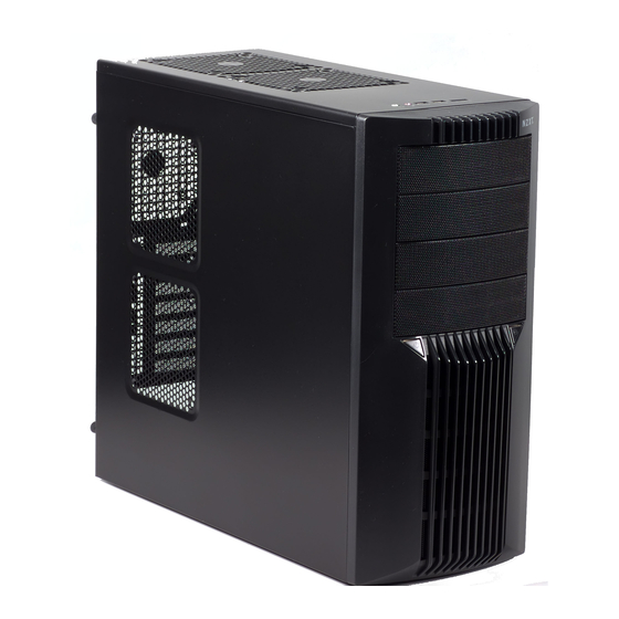
- Page 2 BE TA E vo User’s manual...
- Page 4 With every product, we are still breaking more boundaries and limits. Once again, thank you and all NZXT fans for the support and we hope to bring more amazing products in the coming years.
- Page 5 Before Beginning................3 Getting starting................3 Motherboard Installation ..............4 LED, Power and Reset Installation ..........4 External 5.25” / 3.5” Drive Bay Installation ........7 Internal 3.5” Drive Bay Installation ..........10 Support and Service ..............13 NZXT. 2...
- Page 6 For users building a new system, it is recommended that the side panels are removed before beginning the installation. The following steps will outline the steps to remove the top, side panels and the motherboard tray. 1. Remove the thumb screws securing the side panels. NZXT. 3...
- Page 7 ATX ) with the holes on the motherboard tray 2. Secure the standoffs onto the holes which match your motherboard 3. Lay the motherboard onto the standoffs and then continue to secure the motherboard with the screws provided. NZXT. 4...
- Page 8 Blue when there is activity in the hard drive. (Green/White, +/-) 4. Connect the POWER LED(labeled +P LED/-P LED) to the appropriate headers on your motherboard.(Blue/White,+/-) HDD LED locat ion All White and Black Pin Connectors correspond to ground. NZXT. 5...
- Page 9 Front Audio Ground AGND L-OUT Front Left Channel Audio Signal Line out_L R-OUT Front Right Channel Audio Signal Line out_R BLINE Line L-RET Rear Left Channel Audio Signal out_L BLINE Line R-RET Rear Right Channel Audio Signal out_R NZXT. 6...
- Page 10 3.5” external bay: 1. Remove the front panel of the chassis by pulling from the opening at the bottom of the front panel. 2. Remove the 5.25” black mesh for the 5.25” bay, by pushing the clips aside NZXT. 7...
- Page 11 3. Slide the 5.25” drive in from the front of the chassis. I nser t t he 5.25” Dev ice t hrough t he opening 4. Match the holes with the bay and the screw less bracket NZXT. 8...
- Page 12 At t ach t he screw less brack et m at ching t he 5.25” holes 5. Turn the screw less bracket to lock the drive. NZXT. 9...
- Page 13 In order to allow for optimal airflow and better wire management, Beta EVO allows the user to mount towards the motherboard panel. Please follow the directions below to install the internal 3.5” devices: 1. Open the side panel to gain access inside the chassis.
- Page 14 The Beta EVO is designed to allow for optimal airflow and wire management inside the chassis, please follow the guidelines below on how to use the features. 1. Route PSU cables through the bottom opening and use the punched holes to tie any loose cables 2.
- Page 15 3. Remove heat sinks easily through the CPU punch-out on the motherboard tray NZXT. 12...
- Page 16 You may inquire about replacement parts at rma@nzxt.com. Thank you again for purchasing an NZXT case. If you have any more comments or questions. Please visit our website or send us an email.
- Page 17 NZXT BETA EVO Описание Характеристики...
Need help?
Do you have a question about the BETA Evo and is the answer not in the manual?
Questions and answers