Table of Contents
Advertisement
* INSTALLATION * OPERATION * SERVICE * PARTS *
CAUTION
Read all instruction carefully before starting
the installation or operating the heater.
Save this manual for future reference.
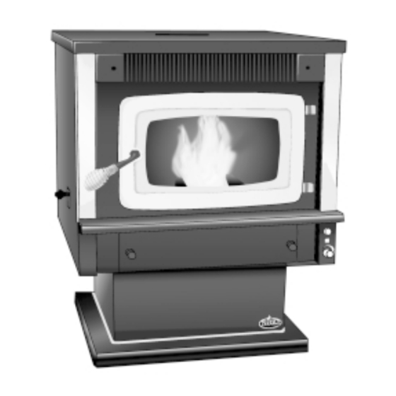
MODEL 100
OWNER'S MANUAL
WOOD PELLET BURNING HEATER
WWW.KOZISTOVES.COM
Manufactured By:
APR Industries Ltd.
1354 Waverley Street
Winnipeg, Manitoba R3T 0P5
Canada
Lithoid in Canada
Rev. April 2003
Page 1
Advertisement
Table of Contents
Troubleshooting

Related Manuals for Kozi 100


Summary of Contents for Kozi 100
- Page 1 MODEL 100 OWNER’S MANUAL WOOD PELLET BURNING HEATER * INSTALLATION * OPERATION * SERVICE * PARTS * Manufactured By: CAUTION APR Industries Ltd. Read all instruction carefully before starting 1354 Waverley Street the installation or operating the heater. Winnipeg, Manitoba R3T 0P5 Save this manual for future reference.
- Page 2 Page 2...
-
Page 3: Table Of Contents
V. Diagrams and Parts List ..............19 1. KOZI KOZI KOZI KOZI KOZI 100 Circuit Diagram ................19 2. Stove Cross Section ....................20 3. Equipment Compartment ................... 21 4. Parts List ....................... 22 5. Accessories List ....................23 VI. WARRANTY .................. 23... -
Page 4: Installation And Operation Manual
I. Installation And Operation Manual This heater is suitable for both mobile home and conventional home installations. Read all instructions carefully before starting installation. Save this manual for future refer- ence. 1. Preamble : Instructions for Safe Installation and Operation. 1. -
Page 5: Clearance To Combustible Walls
9. The heater must be turned off and allowed to cool before cleaning. Make sure there are no hot ashes or embers in the burn pot, ash tray or combustion chamber. Use a brush and scoop to clean. DO NOT USE A VACUUM CLEANER. -
Page 6: Other Clearances And Recommendations
2.4 Other Clearances and Recommendations 1. This heater can be mounted on a combustible floor provided that a non- combustible material, extending minimum of 6 inches (150 mm) in front of the heater, protects the combustible floor. 2. When installed in a mobile home, the heater must be anchored to the floor. -
Page 7: Electrical Requirements
This KOZI pellet burner is certified for 3 inch exhaust venting. 3 inch venting is quite sufficient for most direct vent installations. However, installations with several elbows, long horizontal and/or vertical runs may add excessive resistance against the flow of air, which reduces the volume of air movement and creates burn problems. -
Page 8: Combustion Air Intake Requirements
To calculate EVL use following formula: for each 90 Elbow or T fitting = add 5 EVL for each 45 Elbow = add 3 EVL for each Horizontal run of vent = add 1 EVL per foot of horizontal venting for each Vertical run of vent = add 1/2 EVL per foot of vertical venting YOU MUST USE 4”... -
Page 9: Exhaust Vent Termination Requirements
4.3 Exhaust Vent Termination Requirements A. The exhaust vent must terminate into an open space. Under no circumstances is the vent allowed to terminate into closed or semi- closed spaces. Venting into a garage, under a sundeck, porch or any other space where the concentration of fumes may occur is prohibited. -
Page 10: Typical Installation Configurations
C. When installed in a conventional or a mobile home, check for: a. Clearance to combustibles. d. Power within 6 feet (1.8m) b. Sufficient room to service the unit. e. Access for exhaust venting. c. Access for outside combustion air. f. EVL not exceeding 25ft (7.6m) See Exhaust Venting Require- ments. - Page 11 Free standing through the wall installation. Free standing through the roof installation. Free standing through the wall and the roof installation. Page 11...
-
Page 12: Understanding Your Pellet Burning Heater
1. Component Description 1.1 General Overview The first step in understanding your new KOZI heater is to familiarize yourself with it’s operation. Your heater has 3 main systems: Combustion, Circulation and Feed. The combustion system includes the air intake, burn pot, exhaust fan and exhaust venting. -
Page 13: Exhaust Fan
1.2 Exhaust Fan The purpose of the exhaust fan is to remove the smoke from the combustion chamber. The exhaust fan sucks air from the air intake, through the burn pot and heat exchanger and pushes it through the venting. This fan is a fixed feed fan which is ON whenever the heater starts and remains on until the stove is cool. -
Page 14: Pressure Switch
Once this switch has been tripped, the control system will not allow any more fuel to feed into the burn pot until it has been manually reset. DO NOT RESET THIS UNIT UNTIL THE CAUSE HAS BEEN FOUND AND REPAIRED. Failure of this compo- nent will result in a status light change. -
Page 15: Start Button
2.4 Start Button The start button is located in the middle of the control panel (see diagram). Pushing the start button is the first step in starting the heater. The heater will now run in manual operation mode for 15 minutes. The heater will switch to the automatic mode only if the heater reaches a preset temperature. -
Page 16: Stopping Your Heater
c. The feed system begins to feed. The auger and troubleshooting lights should begin to blink. d. If electric start is installed, it will come on. e. On electric start models, the flame should appear within 5 to 10 minutes. 10. -
Page 17: Maintenance
III. Maintenance During operation, your heater produces a lot of “FLY” ash. The ash will deposit inside the heaters’ air passages and must be removed on a regular basis. A medium size brush is ideal for this purpose. Make sure the heater is cool and there are no embers present in the burn pot, ashtray or combustion chamber. -
Page 18: Trouble Shooting Guide
IV. Trouble Shooting Guide The KOZI model 100 is equipped with a troubleshooting light module, located at the back, bottom right hand corner of the stove. This module consists of a set of three red lights. Under normal working conditions, while the stove is operating, all three lights are BLINKING (on and off). -
Page 19: Diagrams And Parts List
V. Diagrams and Parts List KOZI KOZI 1. KOZI KOZI KOZI 100 Circuit Diagram Page 19... -
Page 20: Stove Cross Section
2. Stove Cross Section * Electric start models only. Page 20... -
Page 21: Equipment Compartment
3. Equipment Compartment Page 21... -
Page 22: Parts List
10016XL Burner Pot Stand 10014XL Auger Rebuild Kit (Includes bushings, auger, auger holder, auger holder 10006-7, 10008, gasket, nut and bolt…) 10008-4, 10035-1 Complete Hopper/Auger Assembly 10006 Not Shown Pedestal Gold Molding 10009-3 KOZI Logo Not Shown 10009-4 Page 22... -
Page 23: Accessories List
5. Accessories List Item No. Description Part No. Optional Equipment Igniter Replacement Kit Igniter Replacement Kit Not Shown Air Intake Kit AK100 Not Shown Air Intake Check Valve CV100 Not Shown Hopper Extension Not Shown Insert Loading Chute LC100 VI. WARRANTY APR Industries Ltd. - Page 24 WWW.KOZISTOVES.COM Page 24...
Need help?
Do you have a question about the 100 and is the answer not in the manual?
Questions and answers