
Related Manuals for eMachines EL1700


Summary of Contents for eMachines EL1700
- Page 1 EL1700 Service Guide Service guide files and updates are available on the ACER/CSD web; for more information, please refer to http://csd.acer.com.tw PRINTED IN TAIWAN...
-
Page 2: Revision History
Revision History Please refer to the table below for the updates made on this service guide. Date Chapter Updates... - Page 3 Copyright Copyright © 2008 by Acer Incorporated. All rights reserved. No part of this publication may be reproduced, transmitted, transcribed, stored in a retrieval system, or translated into any language or computer language, in any form or by any means, electronic, mechanical, magnetic, optical, chemical, manual or otherwise, without the prior written permission of Acer Incorporated.
- Page 4 Disclaimer The information in this guide is subject to change without notice. Acer Incorporated makes no representations or warranties, either expressed or implied, with respect to the contents hereof and specifically disclaims any warranties of merchantability or fitness for any particular purpose.
- Page 5 Conventions The following conventions are used in this manual: SCREEN Denotes actual messages that appear on screen. MESSAGES NOTE Gives additional information related to the current topic. WARNING Alerts you to any physical risk or system damage that might result from doing or not doing specific actions.
- Page 6 Service Guide Coverage This Service Guide provides you with all technical information relating to the BASIC CONFIGURATION decided for Acer's "global" product offering. To better fit local market requirements and enhance product competitiveness, your regional office MAY have decided to extend the functionality of a machine (e.g. add-on card, modem, or extra memory capability).
-
Page 7: Table Of Contents
L1700 Exploded Diagram ........60... - Page 8 viii...
-
Page 9: System Tour
Chapter 1 System Tour Features Below is a brief summary of the computer’s many feature: NOTE: The features listed in this section is for your reference only. The exact configuration of the system depends on the model purchased. Processor Intel Pentium Core 2 Quad Q6600/Q6700/Q8200/Q9300/Q9400/Q9450/Q9550/Q9650 processor •... -
Page 10: System Bios
I/O ports Front • Three USB 2.0 ports • Memory Stick • Memory Stick PRO • Secure Digital (SD) Card • miniSD Card • Headphone/speaker-out/line-out jack • Microphone-in jack • CFI/II (CompactFlash Type I/II) slot • Rear • PS/2 keyboard port •... -
Page 11: System Components
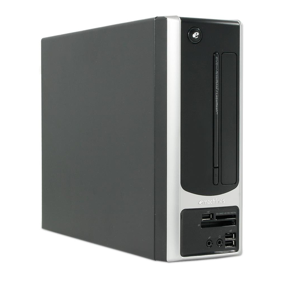
System Components This section is a virtual tour of the system’s interior and exterior components. Front Panel Icon Component Power button/power indicator Optical drive bay door Drive bay door eject button Press to open drive bay door and access the optical drive. USB 2.0 ports Headphone/Speaker-out/line-out jack Microphone-in jack... -
Page 12: Rear Panel
Rear Panel Icon Component Audio in or side speaker jack Line-out jack Microphone/speaker-out/line-in jack Center speaker/subwoofer jack Rear speaker/surround out jack Gigabit LAN port (10/100/1000 Mbps) USB 2.0 ports VGA monitor port PS2 keyboard port PS2 mouse port Power connector Voltage selector switch Kensington lock slot Chapter 1... -
Page 13: Internal Components
Internal Components Component HDD drive Optical drive Expansion cards (expansion cards are not available in this model) Mainboard Heat sink fan assembly Power supply Chapter 1... -
Page 14: System Led Indicators
System LED Indicators This section describes the different system LED indicators. LED indicator Color LED status Description Power Green The system has AC power and is powered on. Green Blinking The system is in standby mode. — System is not powered on. HDD activity Green HDD is installed and functioning correctly. -
Page 15: System Utilities
Chapter 2 System Utilities CMOS Setup Utility CMOS setup is a hardware configuration program built into the system ROM, called the complementary metal- oxide semiconductor (CMOS) Setup Utility. Since most systems are already properly configured and optimized, there is no need to run this utility. You will need to run this utility under the following conditions. When changing the system configuration settings •... -
Page 16: Entering Cmos Setup
Entering CMOS setup Turn on the server and the monitor. If the server is already turned on, close all open applications, then restart the server. During POST, press Delete. If you fail to press Delete before POST is completed, you will need to restart the server. The Setup Main menu will be displayed showing the Setup’s menu bar. -
Page 17: Setup Utility Menus
Setup Utility Menus The Setup Main menu includes the following main setup categories. Product Information • Standard CMOS Features • Advanced BIOS Features • Advanced Chipset Features • Integrated Peripherals • Power Management Setup • PC Health Status • Frequency/Voltage Control •... -
Page 18: Product Information
Product Information The Product Information menu displays basic information about the system. These entries are for your reference only and are not user-configurable. Parameter Description Processor Type Type of CPU installed on the system. Processor Speed Speed of the CPU installed on the system. System Memory Total size of system memory installed on the system. -
Page 19: Standard Cmos Features
Standard CMOS Features Parameter Description Option System Date Set the date following the weekday-month-day-year format. System Time Set the system time following the hour-minute-second format. SATA Port 1/2/3 Press Enter to view detailed device information connected to the SATA connectors. Halt On Determines whether the system will stop for an error during the POST. -
Page 20: Advanced Bios Features
Advanced BIOS Features Parameter Description Option Reset Configuration Data Allows you to manually force BIOS to clear the previously saved Extended System Configuration Data (ESCD) data and reconfigure the settings. When set to no, it lets the BIOS configure all the devices in the system. When set to yes, it lets the OS configure Plug and Play (PnP) devices not required for boot if the system has a PnP OS. -
Page 21: Advanced Chipset Features
Advanced Chipset Features Parameter Description Option Intel EIST When enabled, this feature allows the OS to reduce power consumption. Enabled When disabled, the system operates at maximum CPU speed. Disabled Intel XD Bit When enabled, the processor disables code execution when a worm Enabled attempts to insert a code in the buffer preventing damage and worm Disabled... -
Page 22: Integrated Peripherals
Integrated Peripherals Parameter Description Option Onboard SATA Controller Enables or disables the onboard SATA controller. Enabled Disabled Onboard SATA Mode Select an operating mode for the onboard SATA. AHCI Native IDE Legacy USB Support Enables or disables support for legacy USB devices. Enabled Disabled Onboard Graphics... -
Page 23: Power Management Setup
Power Management Setup Parameter Description Option ACPI Aware O/S Enables or disables the Advanced Configuration and Power Enabled Management (ACPI) function. Disabled ACPI Suspend Mode Select an ACPI state. S3 (STR) S1 (POS) Power On by PCIE Devices Enables or disables to wake up the system from a power saving mode Enabled through an event on PCI Express device. -
Page 24: Pc Health Status
PC Health Status Parameter Description Option Smart FAN Enables or disables the smart system fan control function. Enabled Disabled Chapter 2... - Page 25 Frequency/Voltage Control Parameter Description Option Spread Spectrum Enables or disables the reduction of the mainboard’s EMI. Enabled Note: Remember to disable the Spread Spectrum feature if you are Disabled overclocking. A slight jitter can introduce a temporary boost in clock speed causing the overclocked processor to lock up.
-
Page 26: Bios Security Features
BIOS Security Features Parameter Description Supervisor Password Indicates the status of the supervisor password. User Password Indicates the status of the user password. Change Supervisor Supervisor password prevents unauthorized access to the BIOS Setup Utility. Password Press Enter to change the Supervisor password. Setting a supervisor password Use the up/down arrow keys to select Change Supervisor Password menu then press Enter. -
Page 27: Load Default Settings
Load Default Settings The Load Default Settings menu allows you to load the default settings for all BIOS setup parameters. Setup defaults are quite demanding in terms of resources consumption. If you are using low-speed memory chips or other kinds of low-performance components and you choose to load these settings, the system might not function properly. - Page 28 Save & Exit Setup The Save & Exit Setup menu allows you to save changes made and close the Setup Utility. Chapter 2...
-
Page 29: Exit Without Saving
Exit Without Saving The Exit Without Saving menu allows you to discard changes made and close the Setup Utility. Chapter 2... - Page 30 Chapter 2...
-
Page 31: System Disassembly
Chapter 3 System Disassembly This chapter contains step-by-step procedures on how to disassemble the desktop computer for maintenance and troubleshooting. Disassembly Requirements To disassemble the computer, you need the following tools: Wrist grounding strap and conductive mat for preventing electrostatic discharge •... -
Page 32: Pre-Disassembly Procedure
Pre-disassembly Procedure Before proceeding with the disassembly procedure, perform the steps listed below: Turn off the system and all the peripherals connected to it. Unplug the power cord from the power outlets. Unplug the power cord from the system. Unplug all peripheral cables from the system. Place the system unit on a flat, stable surface. -
Page 33: Main Unit Disassembly
Main Unit Disassembly MAIN UNIT DISASSEMBLY MAIN UNIT SIDE PANEL FRONT BEZEL HEAT SINK FAN ASSEMBLY OPTICAL DISK DRIVE HDD MODULE HDD-ODD BRACKET Ax3, Cx1 POWER SUPPLY MEMORY MODULES VGA CARD TV TUNER CARD FRONT I/O BOARD FRONT I/O AND CARD READER BOARD BRACKET CARD READER... - Page 34 Screw Part No. #6-32*3/16 NI 86.5A5B6.012 #6-32 5MM NI 86.9A5G6.162 Chapter 3...
-
Page 35: Removing The Side Panel
Removing the Side Panel Perform the pre-disassembly procedure described on page 24. Remove the two screws (A) located on the rear edge of the side panel. Screw (Quantity) Color Torque Part No. #6-32 L5 BZN (2) Black 5.5 to 6.5 kgf-cm 86.00J07.B60 Slide the side panel toward the back of the chassis until the tabs on the cover disengage with the slots on the chassis. -
Page 36: Removing The Front Bezel
Removing the Front Bezel Remove the side panel. Refer to the previous section for instructions. Release the front bezel retention tabs from the chassis interior. Pull the bezel away from the chassis. Chapter 3... -
Page 37: Removing The Heat Sink Fan Assembly
Removing the Heat Sink Fan Assembly WARNING:The heat sink becomes very hot when the system is on. NEVER touch the heat sink with any metal or with your hands. See “Removing the Side Panel” on page 27. See “Removing the Front Bezel” on page 28. Use a long-nosed screwdriver to loosen the four screws on the heat sink, in the order as shown below. - Page 38 Lay down the heat sink fan assembly, in an upright position, on top of the optical drive, as shown below, then disconnect the fan cable from the mainboard. Remove the heat sink fan assembly from the chassis then lay it down in an upright position—with the thermal patch facing upward.
-
Page 39: Removing The Processor
Removing the Processor IMPORTANT:Before removing a processor from the mainboard, make sure to create a backup file of all important data. WARNING:The processor becomes very hot when the system is on. Allow it to cool off first before handling. See “Removing the Side Panel” on page 27. See “Removing the Front Bezel”... - Page 40 Pull out the processor from the socket. IMPORTANT:If you are going to install a new processor, note the arrow on the corner to make sure the processor is properly oriented over the socket. Chapter 3...
-
Page 41: Removing The Optical Drive
Removing the Optical Drive See “Removing the Side Panel” on page 27. See “Removing the Front Bezel” on page 28. See “Removing the Heat Sink Fan Assembly” on page 29. See “Removing the Processor” on page 31. Disconnect the data and power cables from the rear of the optical drive and the mainboard. Remove the screw (B) from the optical drive. - Page 42 Pull the drive out of the drive bay. Chapter 3...
-
Page 43: Removing The Hard Disk Drive
Removing the Hard Disk Drive See “Removing the Side Panel” on page 27. See “Removing the Front Bezel” on page 28. See “Removing the Heat Sink Fan Assembly” on page 29. See “Removing the Processor” on page 31. See “Removing the Optical Drive” on page 33. Remove the HDD-ODD bracket. - Page 44 Disconnect the data and power cables from the rear of the hard drive. Disconnect the other end of the data cable from the mainboard. Place the bracket on a clean, static-free work surface. Chapter 3...
- Page 45 10. Remove the HDD module. Remove the four screws (D) that secure the HDD module to the HDD bracket. Screw (Quantity) Color Torque Part No. #6-32*3/16 NI (4) Silver 5.5 to 6.5 kgf-cm 86.5A5B6.012 Slide the HDD out of the bracket. Chapter 3...
-
Page 46: Removing The Power Supply
Removing the Power Supply See “Removing the Side Panel” on page 27. See “Removing the Front Bezel” on page 28. See “Removing the Heat Sink Fan Assembly” on page 29. See “Removing the Processor” on page 31. See “Removing the Optical Drive” on page 33. See “Removing the Hard Disk Drive”... - Page 47 Remove the three screws (A) that secure the power supply to the rear panel. Screw (Quantity) Color Torque Part No. #6-32 L5 BZN (3) Black 5.5 to 6.5 kgf-cm 86.00J07.B60 10. Lift the power supply module out of the chassis. Chapter 3...
-
Page 48: Removing The Memory Modules
Removing the Memory Modules IMPORTANT:Before removing any DIMM from the memory board, make sure to create a backup file of all important data. See “Removing the Side Panel” on page 27. See “Removing the Front Bezel” on page 28. See “Removing the Heat Sink Fan Assembly” on page 29. See “Removing the Processor”... -
Page 49: Removing The Front I/O And Card Reader Boards
Removing the Front I/O and Card Reader Boards See “Removing the Side Panel” on page 27. See “Removing the Front Bezel” on page 28. See “Removing the Heat Sink Fan Assembly” on page 29. See “Removing the Processor” on page 31. See “Removing the Optical Drive”... - Page 50 10. Disconnect the other end of the USB, 1394, and audio cables from the mainboard. 11. Remove the front I/O and card reader board bracket. Remove the two screws (D) that secure the bracket to the chassis. Screw (Quantity) Color Torque Part No.
- Page 51 Push the bracket into the chassis then remove the bracket. 12. Remove the card reader board. Remove the two screws (C) that secure the card reader board to the bracket. Screw (Quantity) Color Torque Part No. #6-32 L6 BZN (2) Silver 3.5 to 4.5 kgf-cm 86.00J44.C60...
- Page 52 13. Remove the front I/O board. Remove the two screws (C) that secure the I/O board to the bracket. Screw (Quantity) Color Torque Part No. #6-32 L6 BZN (2) Silver 3.5 to 4.5 kgf-cm 86.00J44.C60 Pull the I/O board out of the bracket. Chapter 3...
-
Page 53: Removing The Mainboard
Removing the Mainboard See “Removing the Side Panel” on page 27. See “Removing the Front Bezel” on page 28. See “Removing the Heat Sink Fan Assembly” on page 29. See “Removing the Processor” on page 31. See “Removing the Optical Drive” on page 33. See “Removing the Hard Disk Drive”... - Page 54 13. Remove the six screws (C) that secure the mainboard to the chassis. Screw (Quantity) Color Torque Part No. #6-32 L5 BZN (6) Silver 5.7 to 6.3 kgf-cm 86.00J44.C60 14. Lift the board from the chassis. Chapter 3...
-
Page 55: Removing The Power Switch And Led Cable Assembly
Removing the Power Switch and LED Cable Assembly See “Removing the Side Panel” on page 27. See “Removing the Front Bezel” on page 28. See “Removing the Heat Sink Fan Assembly” on page 29. See “Removing the Processor” on page 31. See “Removing the Optical Drive”... - Page 56 13. Pull the LED bracket up and lift up from the chassis. 14. Release the two locking tabs (1) and gently pull the HDD LED cable out (2). Chapter 3...
- Page 57 15. Remove the power switch cable. Release the two locking tabs (1), pull power switch cable bracket out of the LED bracket (2). Grasp the power switch cable bracket and pull the power switch cable out of the bracket. 16. Release the two locking tabs (1) and gently pull the power LED cable out (2). Chapter 3...
- Page 58 Chapter 3...
-
Page 59: System Troubleshooting
Chapter 4 System Troubleshooting This chapter provides instructions on how to troubleshoot system hardware problems. Hardware Diagnostic Procedure IMPORTANT:The diagnostic tests described in this chapter are only intended to test Acer products. Non-Acer products, prototype cards, or modified options can give false errors and invalid system responses. -
Page 60: System Check Procedures
System Check Procedures Power System Check If the system will power on, skip this section. Refer to System External Inspection. If the system will not power on, do the following: Check if the power cable is properly connected to the system and AC source. •... -
Page 61: Beep Codes
Beep Codes Beep codes are used by the BIOS to indicate a serious or fatal error to the end user. Beep codes are used when an error occurs before the system video has been initialized. Beep codes will be generated by the system board speaker, commonly referred to as the PC speaker. -
Page 62: Online Support Information
Online Support Information This section describes online technical support services available to help you repair the desktop computer. If you are a distributor, dealer, ASP or TPM, please refer your technical queries to your local Acer branch office. Acer Branch Offices and Regional Business Units may access our website at http://global.acer.com/ support/index. -
Page 63: System Block Diagram
Chapter 5 System Block Diagram and Board Layout System Block Diagram Chapter 5... -
Page 64: Board Layout
Board Layout Mainboard Chapter 5... - Page 65 Code Description Code Description PWR2 24-pin ATX power connector AUDIO1 Center speaker/subwoofer jack, Audio in or side speaker jack, Surround L/R speaker jack, and Headphone/analog speakers jack or front speakers jack, Microphone port, and S/PDIF port CLR_CMOS1 Clear CMOS jumper USBLAN1 Top: Gigabit LAN port Bottom: USB Port (2)
-
Page 66: System Jumpers
System Jumpers Name Location Default Settings General Purpose Input/Output GPIO32 Short GPIO33 Open Clear CMOS CLR_CMOS1 Normal (default) Clear CMOS Chapter 5... -
Page 67: Fru (Field Replaceable Unit) List
Chapter 6 FRU (Field Replaceable Unit) List This chapter offers the FRU (Field Replaceable Unit) list in global configuration of the eMachines L1700 desktop computer. Refer to this chapter whenever ordering the parts to repair or for RMA (Return Merchandise Authorization). -
Page 68: Emachines L1700 Exploded Diagram
L1700 Exploded Diagram NOTE: This section will be updated when more information becomes available. Chapter 6... -
Page 69: Emachines L1700 Fru List
L1700 FRU List Acer Component Part Name Description Part Number Accessory RECEIVER PHILIPS VISTA MCE PHILIPS VISTA MCE RV.11000.003 TRANSCEIVER WITH 1 BLASTER TRANSCEIVER OVU412000 RECEIVER SMK RECEIVER VISTA RC RECEIVER+IR BLASTER RV.11000.004 MCE RECEIVER WITH ONE IR RXX6000... - Page 70 Acer Component Part Name Description Part Number TV tuner card TV TUNNER CARD YUAN TV TUNER CARD PE585QA PCI-E TU.10500.010 PE585QA PCI-E HYBRID S/W MPEG (ATSC+NTSC) W/LP BRKT TV TUNNER CARD HAUPPAUGE HAUPPAGUE WIN-TV HVR-1200 TU.10500.011 HVR-1200 PCIE HYBRID DVB-T S/ PCIE W ENCORDER W/LP BRKT Wireless LAN...
- Page 71 Acer Component Part Name Description Part Number CPU INTEL CELERON 450 2.XG IC CPU CONROE LITE 450 2.2G KC.D0001.450 512K 800FSB 35W HH80557RG049512 891507 SLAFZ CPU INTEL CELERON DUA CORE IC CPU CONROE LITE E1200 1.6G KC.12001.CDE E1200 1.60G 512K 800FSB 65W M0 HH80557PG025D 893843 SLAQW CPU INTEL PENTIUM DUAL CORE IC CPU CONROE E2200 2.2G...
- Page 72 Acer Component Part Name Description Part Number DVD-RW drive ODD HLDS SUPER-MULTI DRIVE S-MULTI HH HLDS GH-15F LF KU.0160D.043 HH LABELFLASH 16X GH-15F LF BLACK BEZEL SATA ODD SONY SUPER-MULTI DRIVE S-MULTI HH SONY AD-7203S LF KU.0160E.015 HH 16X AD-7203S LF SATA DVD-RW PHILIPS SUPER-MULTI S-MUL HH SATA PLDS DH-16A6S KU.0160F.005...
- Page 73 Acer Component Part Name Description Part Number KEYBOARD PS2 105KEY KB PS2 KB-0759 FRENCH KB.PS203.109 CHICONY KB-07596F12552V BLACK105 FRENCH BLACK KEYBOARD PS2 104KEY KB PS2 KB-0759 RUSSIAN BLACK KB.PS203.121 CHICONY KB-07593S32552V RUSSIAN BLACK KEYBOARD PS2 104KEY KB PS2 KB-07593US2552V US KB.PS203.096 CHICONY KB-07593US2552V BLAC...
- Page 74 Acer Component Part Name Description Part Number KEYBOARD PS2 105KEY KB PS2 KB-0759 DUTCH BLACK KB.PS203.112 CHICONY KB-07596NL2552V DUTCH BLACK KEYBOARD PS2 105KEY KB PS2 KB-0759 SWISS/G BLACK KB.PS203.113 CHICONY KB-07596CH2552V SWISS/G BLACK KEYBOARD PS2 105KEY KB PS2 KB-0759 BELGIUM BLACK KB.PS203.114 CHICONY KB-07596B02552V BELGIUM BLACK...
- Page 75 Acer Component Part Name Description Part Number KEYBOARD USB 104KEY KB USB KU-0760 T-CN BLACK KB.USB03.063 CHICONY KU-07603RD2552V T-CN 104K BLACK KEYBOARD USB 104KEY KB USB KU-0760 S-CN BLACK KB.USB03.064 CHICONY KU-07603RE2552V S-CN 104K BLACK KEYBOARD USB 104KEY KB USB KU-0760 US-I BLACK 104K KB.USB03.065 CHICONY KU-07603U42552V US INTERNATIONAL BLACK...
- Page 76 Acer Component Part Name Description Part Number KEYBOARD USB 105KEY KB USB KU-0760 ICELANDIC KB.USB03.081 CHICONY KU-07606IC2552V BLACK ICELANDIC KEYBOARD USB 105KEY KB USB KU-0760 NORWEGIAN KB.USB03.082 CHICONY KU-07606N02552V BLACK NORWEGIAN BLACK KEYBOARD USB 104KEY KB USB KU-0760 HEBREW BLACK KB.USB03.083 CHIOCNY KU-07603HB2552V HEBREW BLACK...
- Page 77 Acer Component Part Name Description Part Number Mainboard MAINBOARD PUG ENMCP73VE ENMCP73PV NVIDIA MCP73PV W/ MB.SB801.002 NVIDIA MCP73PVE W/1394 LF W/ Memory MEMORY UNIFOSA UNB-DIMM DIMM 1G KN.1GB0H.009 DDRII 800MHZ 1GB GU341G0ALEPR6B2C6CE GU341G0ALEPR6B2C6CE LF MEMORY NANYA UNB-DIMM DIMM 1G NT1GT64U88D0BY-AD KN.1GB03.024 DDRII 800MHZ 1GB NT1GT64U88D0BY-AD...
- Page 78 Acer Component Part Name Description Part Number Screws SCRW I NO6-32 L5 BZN SCRW I NO6-32 L5 BZN 86.00J07.B60 SCRW PAN #6-32 L6 NI BOXER SCRW PAN #6-32 L6 NI BOXER 86.00J44.C60 SCRW PAN M3 L5 BZN SCRW PAN M3 L5 BZN 86.1A324.5R0 SCREW FLAT #6-32*3/16 NI SCREW FLAT #6-32*3/16 NI...
-
Page 79: Technical Specifications
Appendix A Technical Specifications This section provides technical specifications for the system. Processor Intel Core 2 Quad Item Specification Model Number Q6600 Q6700 Q8200 Q9300 Q9400 Q9450 Q9550 Q9650 Core (nm) L2 Cache Size (MB) Clock Speed (GHz) 2.66 2.33 2.66 2.66 2.83... - Page 80 Intel Pentium Dual-Core Item Specification Model Number E2180 E2200 E2220 E5200 Architecture (nm) L2 Cache Size (MB) Clock Speed (GHz) Front Side Bus (MHz) 800 Frequency (MHz) 2000 2200 2400 2500 Socket LGA 775 LGA 775 LGA 775 LGA 775 Clock Multiplier 12.5x Voltage (V)
- Page 81 System Board Major Chips Item Specification System core logic NVIDIA NForce MCP73PV 1048 BGA Memory controller NVIDIA NForce MCP73PV 1048 BGA Storage controller NVIDIA NForce MCP73PV 1048 BGA Video controller NVIDIA NForce MCP73PV 1048 BGA PCI controller NVIDIA NForce MCP73PV 1048 BGA LAN controller NVIDIA NForce MCP73PV 1048 BGA + Realtek RTL8211C Audio controller...
- Page 82 Hard Disk Drive Item Specification Storage controller NVIDIA NForce MCP73PV 1048 BGA Vendor Seagate HGST Model no. WD1600AAJS-22WAA0 ST3160815AS HDS721616PLA380 WD3200AAJS-22B4A0 ST3320813AS HDP725032GLA380 WD5000AAJS-22A8B0 ST3500820AS HDP725050GLA380 WD6400AAKS-22A7B0 Interface SATA SATA SATA Size 3.5-inch 3.5-inch 3.5-inch Transfer rate (Gb/s) 100 MBps Spindle speed (RPM) 7200 7200...
- Page 83 Optical Drive Super Multi Item Specification Vendor HLDS PLDS Sony Model name GH-15F DH-16A3S AD-7203S Drive type Super Multi DVD-ROM Super Multi — DVD-R: 20x max. DVD Write Speed — +R: 20x max. DVD-RW: 6x max. DVD +RW: 8x max. DVD-R DL: 12x max.
- Page 84 Appendix A...
Need help?
Do you have a question about the EL1700 and is the answer not in the manual?
Questions and answers