Advertisement
Available languages
Available languages
Operator: Save these instructions for future use!
FAILURE TO READ AND FOLLOW ALL INSTRUCTIONS CAREFULLY BEFORE
INSTALLING OR OPERATING THIS CONTROL COULD CAUSE PERSONAL
INJURY AND/OR PROPERTY DAMAGE.
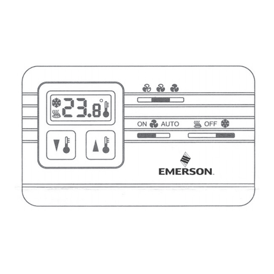
DESCRIPTION
The 1H11G thermostat controls line voltage valves and/or blower
motors on fan coil units in heating/cooling systems. It features
a system switch for manual selection of heat-off-cool, a three
speed manual fan switch, an adjustable temperature range of
5° to 35°C.
Terminal block is provided for connection to field wiring. The
thermostat can be wired to perform the following functions:
- Thermostat cycles both fan and valve.
- Thermostat cycles fan only.
- Thermostat cycles valve only.
PRECAUTIONS
If in doubt about whether your wiring is millivolt, line, or low
voltage, have it inspected by a qualified heating and air condi-
tioning contractor, electrician, or someone familiar with basic
electricity and wiring.
Do not exceed the specification ratings.
All wiring must conform to local and national electrical codes
and ordinances.
This control is a precision instrument, and should be handled
carefully. Rough handling or distorting components could cause
the control to malfunction.
SPECIFICATIONS
Switch Action: SPST
(Heating - open on rise)
(Cooling - close on rise)
Temperature Range: 5°C to 35°C
CAUTION
!
When the thermostat is set below 5°C, damage to the
building and/or contents may result due to freezing.
This is possible due to factory calibration tolerances,
thermostat location and operating characteristics of
the heating equipment.
White-Rodgers is a division
of Emerson Electric Co.
www.white-rodgers.com
1H11G-101
Fan Coil Heating-Cooling Thermostat
Electronic Non-Programmable
Installation INSTRUCTIONS
CAUTION
!
To prevent electrical shock and/or equipment damage,
disconnect electric power to system at main fuse or
circuit breaker box until installation is complete.
WARNING
!
Do not use on circuits exceeding specified voltage.
Higher voltage will damage control and could cause
shock or fire hazard.
System Switch: Heat - Off - Cool
Fan Switch: Low - Medium - High
Contact Structure: Snap action
Electrical Rating: 6A, 120 VAC, 50/60 Hz Inductive
3A, 240 VAC, 50/60 Hz Inductive
12A, 120 VAC, 50/60 Hz Resistive
6A, 240 VAC, 50/60 Hz Resistive
Agency Approvals:
The Emerson logo is a
trademark and a service mark
of Emerson Electric Co.
PART NO. 37-6872B
Replaces 37-6872A
1011
Advertisement
Table of Contents

Subscribe to Our Youtube Channel
Related Manuals for Emerson White Rodgers 1H11G-101


Summary of Contents for Emerson White Rodgers 1H11G-101
- Page 1 This is possible due to factory calibration tolerances, Agency Approvals: thermostat location and operating characteristics of the heating equipment. White-Rodgers is a division PART NO. 37-6872B The Emerson logo is a of Emerson Electric Co. trademark and a service mark Replaces 37-6872A of Emerson Electric Co. www.white-rodgers.com...
- Page 2 INSTALLATION SELECT THERMOSTAT LOCATION NOTE Proper location insures that the thermostat will provide a com- This typical wiring diagram (Figure 1) shows only the terminal fortable home temperature. Observe the following general rules identification and wiring hookup. Always refer to wiring instruc- when selecting a location: tions, provided by equipment manufacturer, for system hookup operation.
- Page 3 Aprobaciones de organismos reglamentarios: y las características de funcionamiento del equipo de calefacción. White-Rodgers es una división N° DE PIEZA 37-6872B El logotipo de Emerson es una de Emerson Electric Co. Reemplaza 37-6872A marca y una marca de servicio www.white-rodgers.com de Emerson Electric Co.
- Page 4 INSTALACIÓN SELECCIONE LA UBICACIÓN DEL NOTA TERMOSTATO Este diagrama de conexiones típico (figura 1) muestra únicamente La ubicación adecuada asegura que el termostato proporcione una la identificación de los terminales y la conexión de los cables. temperatura ambiente agradable. Tenga en cuenta las siguientes reglas Refiérase siempre a las instrucciones de conexión suministra- generales al elegir una ubicación: das por el fabricante del equipo para el funcionamiento de las...
Need help?
Do you have a question about the White Rodgers 1H11G-101 and is the answer not in the manual?
Questions and answers