Table of Contents
Advertisement
Quick Links
Congratulations on owning a Scag mower! This manual contains the operating
instructions and safety information for your Scag mower. Reading this manual
can provide you with assistance in maintenance and adjustment procedures to
keep your mower performing to maximum efficiency. The specific models that
this book covers are listed on the inside cover. Before operating your machine,
please read all the information enclosed.
© 2014
Scag Power Equipment
Division of Metalcraft of Mayville, Inc.
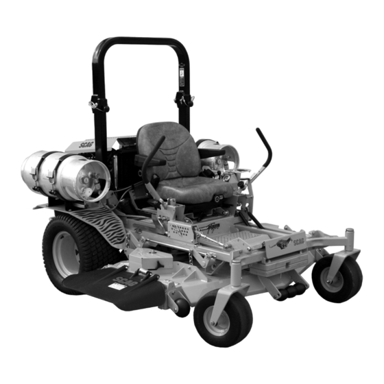
OPERATOR'S
MANUAL
Turf Tiger
Dual Fuel
Model:
STT61V-31KB-DF
STT72V-31KB-DF
PART NO. 03331
PRINTED 6/2014
PRINTED IN USA
Advertisement
Table of Contents

Related Manuals for Scag Power Equipment Turf Tiger STT61V-31KB-DF


Summary of Contents for Scag Power Equipment Turf Tiger STT61V-31KB-DF
- Page 1 Model: STT61V-31KB-DF STT72V-31KB-DF Congratulations on owning a Scag mower! This manual contains the operating instructions and safety information for your Scag mower. Reading this manual can provide you with assistance in maintenance and adjustment procedures to keep your mower performing to maximum efficiency. The specific models that this book covers are listed on the inside cover.
- Page 2 CONCERN, PRUDENCE, AND PROPER TRAINING OF THE PERSONNEL INvOLvED IN THE OPERATION, TRANSPORT, MAINTENANCE, AND STORAGE OF THE EqUIPMENT. This manual covers the operating instructions and illustrated parts list for: STT61v-31KB-DF with a serial number of K2100001 to K2199999 STT72v-31KB-DF...
-
Page 3: Table Of Contents
Table of Contents Table of Contents SECTION 1 - GENERAL INFORMATION ...................1 1.1 INTRODUCTION ............................1 1.2 DIRECTION REFERENCE ...........................1 1.3 SERvICING THE ENGINE AND DRIvE TRAIN COMPONENTS ..............1 1.4 SYMBOLS ..............................2 SECTION 2 - SAFETY INFORMATION ..................3 2.1 INTRODUCTION ............................3 2.2 SIGNAL WORDS ............................3 2.3 BEFORE OPERATION CONSIDERATIONS ....................3 2.4 OPERATION CONSIDERATIONS ........................4... - Page 4 7.12 COOLING SYSTEM ..........................40 7.13 BODY, DECK, AND UPHOLSTERY ......................41 SECTION 8 - ILLUSTRATED PARTS LIST ................42 8.1 SCAG APPROvED ATTACHMENTS AND ACCESSORIES..............42 61v & 72v CUTTER DECKS ...........................44 CUTTER DECK CONTROLS ...........................46 SHEET METAL COMPONENTS ........................48 STT ROLL-OvER PROTECTION SYSTEM .....................50 STT SUSPENSION SEAT ..........................52...
-
Page 5: General Information
We encourage you to contact your dealer for repairs. All Scag dealers are informed of the latest methods to open or removed. Under no circumstances should service this equipment and provide prompt and efficient your mower be operated without these devices service in the field or at their service shop. -
Page 6: Symbols
Section 1 SYMBOLS SYMBOL DESCRIPTION SYMBOL DESCRIPTION Choke Transmission Parking Brake Spinning Blade 48071S On/Start Spring Tension on Idler Off/Stop Falling Hazard Thrown Object Hazard Fast Slow Continuously Variable - Linear Cutting Element - Basic Symbol Pinch Point Cutting Element - Engage 481039S Hour meter/Elapsed Operating Hours Cutting Element - Disengage... -
Page 7: Safety Information
Scag Service Dealer or by contacting Scag Power Equipment, Service Department at P.O. Box 152, Mayville, WI 53050 or contact us via the Internet at www.scag.com. The manual for this machine can be downloaded by using The signal word “CAUTION” is a reminder of safety practices... -
Page 8: Operation Considerations
Section 2 DO NOT allow children to ride or play on the Be sure the interlock switches are functioning machine, it is not a toy. correctly. Clear the area to be mowed of objects that could be Fuel is flammable; handle it with care. Fill the fuel picked up and thrown by the cutter blades. - Page 9 Section 2 Reduce speed and exercise extreme caution on Take all possible precautions when leaving the slopes and in sharp turns to prevent tipping or loss machine unattended, such as disengaging the of control. Be especially cautious when changing mower, lowering the attachments, setting the parking directions on slopes.
-
Page 10: Roll-Over Protection System
Section 2 Use care when approaching blind corners, shrubs, Lower the roll bar only when absolutely necessary. trees, or other objects that may obscure vision. To lower the roll bar, remove the hairpin cotter pins NEVER leave the machine running unattended. and remove the two (2) lock pins. - Page 11 Section 2 WARNING Failure to properly inspect and maintain the seat belt can cause serious injury or loss of life. Check the full length of the seat belt webbing for cuts, wear, fraying, dirt and stiffness. See Figure 2-3. Figure 2-4. Slope Angle Graph Check the seat belt webbing in areas exposed to ultra violet rays from the sun or extreme dust or...
-
Page 12: Maintenance Considerations & Storage
Check blade If you need service on your hydraulic system, mounting bolts frequently to be sure they are tight. please see your authorized Scag dealer. Do not change the engine governor settings or overspeed the engine. See the engine operator's Let the engine cool before storing. -
Page 13: Safety And Instructional Decals
Section 2 SAFETY AND INSTRUCTIONAL DECALS WARNING INSTALL BELT COvER BEFORE OPERATING MACHINE READ OPERATOR'S MANUAL 483402 483407 483402 483407 FORWARD REvERSE 481568 WARNING 483406 Operation of this equipment may create sparks that can start res around dry vegetation. A spark arrestor may be required. -
Page 14: Specifications
Section 3 SPECIFICATIONS ENGINE General Type ....................Heavy Duty Industrial/Commercial Gas/LP Brand ........................Kubota Dual Fuel [Spec. #DF972-E2] Model ................................Kubota DF972 Horsepower ..................LP = 29 HP at 3600 RPM, Gas = 31 HP at 3600 RPM Type ................. 4 Cycle Dual Fuel, 3 Cylinder, Horizontal Shaft, Water Cooled Displacement ............................. -
Page 15: Cutter Deck
Acres Per Day ........................23.7 ........28 The preceding chart will aid you in determining how many acres your Scag mower will cut per day. The chart is an estimate based on 8 hours per day cutting time at 6 MPH with an allowance for overlap and turns. -
Page 16: Operating Instructions
Section 4 OPERATING INSTRUCTIONS Mower Deck Switch (Figure 4-1). Used to engage CAUTION and disengage the mower drive system. Pulling up on the switch will engage the deck drive. Pushing down on the switch will disengage the deck drive. Do not attempt to operate this mower unless you Engine Choke Control (Figure 4-1). -
Page 17: Safety Interlock System
Section 4 Hourmeter (Figure 4-1). Cutting Height Adjustment (Figure 4-1). Indicates the number of Used to hours the engine has been operated. It operates set the cutter deck at the desired cutting height. whenever the key is on. Has preset maintenance Deck Release Lever (Figure 4-1). -
Page 18: Initial Run-In Procedures
Section 4 INITIAL RUN-IN PROCEDURES Turn the ignition key to the START position and release the key as soon as the engine starts. Do not hold the key in the START position for more FIRST DAY OF USE OR APPROxIMATELY 20 HOURS than 15 seconds at a time. -
Page 19: Engaging The Deck Drive (Cutter Blades)
Section 4 To steer the mower right while traveling forward, pull the To steer left while traveling in reverse, allow the left right steering control lever back. The further the lever is steering control lever to move forward. The further the pulled back, the quicker the mower will turn right. -
Page 20: Hillside Operation
Section 4 Always operate the engine at full throttle to properly Slow the engine to idle speed. maintain cutting speed. If the engine starts to lug Engage the parking brake. down, reduce the forward speed and allow the engine to operate at maximum RPM. Turn the ignition key to the OFF position and remove the key. -
Page 21: Moving Mower With Engine Stopped
Section 4 If the discharge chute becomes clogged, shut off The discharge chute must not be removed and the engine and remove the ignition key. Using a stick must be kept in the lowest position to deflect grass or similar item, dislodge the clogged material. Then clippings and thrown objects downward. -
Page 22: Adjusting The Steering Levers
Section 4 If adjustment of the steering levers is needed, use LANYARD the following instructions to adjust. A. Loosen the tension knob on the lever assembly. B. Rotate the steering lever forward or backward to achieve the optimum operating position. C. -
Page 23: Adjusting The Height Adjust Pedal
Section 4 4.15 ADJUSTING THE HEIGHT ADJUST PEDAL Position the seat to the desired location. While in the operator's position with out the engine running, push down on the height adjust pedal to check for full function control. The height adjust pedal can be located in three (3) different positions for operator comfort and control. -
Page 24: Troubleshooting Cutting Conditions
Section 5 TROUBLESHOOTING CUTTING CONDITIONS CONDITION CAUSE CURE STRINGERS - OCCASIONAL Low engine RPM Run engine at full RPM BLADES OF UNCUT GRASS Ground speed too fast Slow speed to adjust for conditions Wet grass Cut grass after it has dried out Dull blades, incorrect sharpening Sharpen blades Deck plugged, grass accumulation... - Page 25 Deck plugged, grass accumulation Clean underside of deck Too much blade angle (deck pitch) Adjust pitch and level Deck mounted improperly See your authorized SCAG dealer Bent spindle area See your authorized SCAG dealer Width of Deck Dull blade Sharpen blade...
- Page 26 Blades not mounted evenly Adjust pitch and level OF CUTTING PATH Bent blade Replace blade Internal spindle failure See your authorized SCAG dealer Mounting of spindle incorrect See your authorized SCAG dealer Width of Deck SGB024 SLOPE CUT - SLOPING RIDGES...
-
Page 27: Adjustments
“ENGAGE” position and the parking brake will allow the mower to move. If the following procedures do not allow you to engage the parking brake properly, contact your Scag dealer for further brake adjustments. 390S0152-1 Position a floor jack under the rear of the machine. -
Page 28: Travel Adjustments
Section 6 TRAvEL ADJUSTMENTS LOOSEN HERE Neutral or tracking adjustments will need to be made if: A. The steering control levers are in the neutral position and the machine creeps forward or backward. (Neutral Adjustment, See Below). B. The steering control levers are in the full forward position and the mower pulls to one side or the other when traveling in a forward direction. -
Page 29: Throttle Control And Choke Adjustments
The engine and drive unit can get hot during operation causing burn injuries. Allow engine These adjustments must be performed by your Scag dealer and drive components to cool before making any to ensure proper and efficient running of the engine. Should adjustments. -
Page 30: Belt Alignment
400 hours / 2 years, whichever occurs first. LOOSEN HERE BELT ALIGNMENT Belt alignment is important for proper performance of your Scag mower. If you experience frequent belt wear or breakage, see your authorized Scag service center for Figure 6-5. Cutter Deck Level Adjustment belt adjustment. - Page 31 Section 6 JAM NUT LANYARD LOOSEN HERE ADJUST HERE 390S0174-1 390S014A-2 Figure 6-6. Cutter Deck Level Adjustment HEIGHT ADJUSTMENT PEDAL Using a wrench on the jam nut (See Figure 6.6) turn Figure 6-7. Cutter Deck Height Adjustment the adjusting rods until the proper pitch is obtained on both the RH and the LH side of the cutter deck.
- Page 32 Section 6 CUSTOM-CUT BAFFLE ADJUSTMENT To adjust the Custom-Cut Baffle height: Place the cutter deck in the transport position. The Custom-Cut Baffle is designed to deliver optimum airflow and superior cutting performance in any type of Remove the hardware securing the Custom-Cut grass.
-
Page 33: Electric Clutch Adjustment
Section 6 ELECTRIC CLUTCH ADJUSTMENT ADJUSTMENT NUTS The electric clutch serves two functions in the operation of the mower. In addition to starting and stopping the power flow to the cutter blades, the clutch also acts as a brake to assist in stopping blade rotation when the PTO is switched off or the operator presence circuit is interrupted. -
Page 34: Maintenance
Section 7 MAINTENANCE MAINTENANCE CHART - RECOMMENDED SERvICE INTERvALS HOURS PROCEDURE COMMENTS BREAK-IN (FIRST 10) Check all hardware for tightness Check hydraulic oil level See paragraph 7.3 C h e c k a l l b e l t s f o r p r o p e r See paragraph 7.8 alignment Change engine oil and filter... -
Page 35: Lubrication
Section 7 MAINTENANCE CHART - RECOMMENDED SERvICE INTERvALS (CONT'D) HOURS PROCEDURE COMMENTS BREAK-IN (FIRST 10) Check lubricant in cutter deck See paragraph 7.11 gearbox Apply grease to fittings See paragraph 7.2 Check hardware for tightness Change engine oil filter See paragraph 7.4 Check hydraulic oil level See paragraph 7.3 Replace engine fuel filter... -
Page 36: Lubrication Fitting Points
Section 7 GREASE FITTING LUBRICATION LUBRICANT / INTERVAL LITHIUM MP WHITE GREASE 2125 ( 40 HOURS / WEEKLY ) CHASSIS GREASE ( 100 HOURS / BI-MONTHLY ) CHASSIS GREASE ( 200 HOURS / MONTHLY ) CHASSIS GREASE ( 500 HOURS / YEARLY ) STT-DF Grease Points Figure 7-1. -
Page 37: Hydraulic System
Section 7 HYDRAULIC SYSTEM - IMPORTANT - The hydraulic oil should be changed if you notice the presence of water or a rancid odor to the A. CHECKING HYDRAULIC OIL LEvEL hydraulic oil. The hydraulic oil level should be checked after the first 10 Park the mower on a level surface and stop the hours of operation. -
Page 38: Engine Oil
Section 7 C. CHANGING HYDRAULIC OIL FILTER ELEMENT The hydraulic oil filter should be changed after every 500 hours of operation or annually, whichever occurs first. Remove the oil filter element and properly discard it. See Figure 7-3. Fill the new filter with clean oil and install the filter. - Page 39 Always place after 1000 hours of operation or annually, whichever containers on the ground away from your vehicle occurs first. Contact your authorized Scag service center before filling. for details and maintenance. See Engine Owner's manual...
-
Page 40: Engine Air Cleaner
Section 7 ENGINE AIR CLEANER WARNING A. CLEANING AND/OR REPLACING AIR CLEANER ELEMENT DO NOT overfill. Follow approved procedures for filling. For any air cleaner, the operating environment dictates the air cleaner service periods. Inspect and clean the air This cylinder is designed to contain LP Gas; a cleaner element after every 100 hours of operation or flammable liquid and gas under pressure. -
Page 41: Drive Belts
If you experience frequent belt wear or breakage, see your authorized Scag service center for belt DO NOT charge a frozen battery. It may explode and adjustment. - Page 42 The cutter blades should be balanced to 1-1/2 oz-in. Do not attempt to straighten a bent blade, and See your authorized Scag dealer for blade balancing never weld a broken or cracked blade. Always or special tools, if you choose to balance your own replace it with a new blade to assure safety.
-
Page 43: Tires
Section 7 7.10 TIRES CAUTION Check the tire pressures after every 8 hours of operation or daily. Inspect the cutter blade spacer(s) and washer for wear and/or cupping. Replace the worn parts. Caster Wheels Flat Free Worn spacer(s) and/or washer will not allow Drive Wheels 12 PSI proper tightening of the cutter blade and can lead... -
Page 44: Cooling System
The cooling system should be flushed and the coolant replaced every 500 hours of operation or WARNING annually. See your Scag dealer for proper coolant replacement. To avoid burns, always allow the engine to cool B. CLEANING THE RADIATOR DEBRIS SCREEN before removing the radiator cap. -
Page 45: Body, Deck, And Upholstery
C. CHECKING THE FAN BELT TENSION (LIqUID- COOLED ENGINES ONLY) Periodically check the fan belt tension. The belt should deflect 1/2" with 10 pounds of pressure. See your Scag dealer if the belt is in need of adjustment or replacement. 7.13... -
Page 46: Illustrated Parts List
Section 8 ILLUSTRATED PARTS LIST SCAG APPROvED ATTACHMENTS AND ACCESSORIES Attachments and accessories manufactured by companies other than Scag Power Equipment are not approved for use on this machine. Scag approved attachments and accessories: • GC-3B (p/n 900S) - Requires a 900X (61 STT/SCZ Install Kit) •... - Page 47 Section 8...
-
Page 48: 61V & 72V Cutter Decks
Section 8 61v & 72v CUTTER DECKS 14 15 16 72V Only 54 55 2012 STT61V CD... - Page 49 Section 8 61v & 72v CUTTER DECKS Ref. Ref. Part No. Description Part No. Description 481625-01 Wing Nut, 3/8-16 424841 Baffle, Custom Cut 61V 424917 Baffle, Custom Cut 72V 462360 Belt Cover Assembly 04003-23 Bolt, Carriage 3/8-16 x 1” 462398 Belt Cover Assy., RH 424209 Discharge Baffle 61V...
-
Page 50: Cutter Deck Controls
Section 8 CUTTER DECK CONTROLS CUTTER DECK STT-28CAT 2008CDC... - Page 51 Section 8 CUTTER DECK CONTROLS Ref. Part No. Description 481764 Link, Deck Lift 04020-28 Nut, Jam 1/2-20 LH 481766 Rod End, Female - 1/2-20 LH 04050-10 Ring, Retaining 1/2” External “E” 45905 Bellcrank Weldment, RH Rear 43487 Pin, Decklift 482429 Slide Weldment, Height Adjustment 04009-02 Bolt, Shoulder 1/2 x 3/4”...
-
Page 52: Sheet Metal Components
Section 8 SHEET METAL COMPONENTS STT-31DF SMC rev1... - Page 53 Nut, Elastic Stop 3/8-16 43606 Spacer Bushing 491729 Seat Plate Weldment w/Decal 452026 Fender Weldment, RH 04003-01 Bolt, Carriage 1/4-20 x 6” Battery (not avail. through Scag) 422682 Cover, Battery 04003-12 Bolt, Carriage 5/16-18 x 3/4” 462007 Plate, Battery Box 48661 Rubber Pad 04029-01 Wing Nut, 1/4-20 x 3/4”...
-
Page 54: Stt Roll-Over Protection System
Section 8 STT ROLL-OvER PROTECTION SYSTEM... - Page 55 Section 8 STT ROLL-OvER PROTECTION SYSTEM Ref. Part No. Description 462210 STT, ROPS 04001-82 Bolt, Hex Head 1/2-13 x 4-1/2” (upper) 04001-87 Bolt, Hex Head 1/2-13 x 4” (lower) 04021-19 Nut, Center Lock 1/2-13 04040-13 Flatwasher, 1/2-.562 x 1.375 x .109 484168 Pin Assembly (incl.
-
Page 56: Stt Suspension Seat
Section 8 STT SUSPENSION SEAT... - Page 57 Section 8 STT SUSPENSION SEAT Ref. Part No. Description 922A Suspension Seat Assembly w/seat belt 484709 Armrest Kit, LH 484717 Seat Belt Kit 484711 Recliner Knob Kit 484710 Armrest Kit, RH 484712 Back Cover 481638 Seat Switch 484713 Track Kit 484714 Suspension Knob Kit 484708...
-
Page 58: Deck Drive Components
Section 8 DECK DRIvE COMPONENTS 19 11 Frame STT CAT 2008 DDC... - Page 59 Section 8 DECK DRIvE COMPONENTS Ref. Ref. Part No. Description Part No. Description 482433 Rod Assembly, Clutch Anti-Rotation 04019-02 Nut, Serrated Flange 1/4-20 425133 Belt Guard, Rear 04001-11 Bolt, Hex Head 5/16-18 x 1-1/2” 04040-04 Flatwasher, 5/16” 04003-07 Bolt, Carriage 1/4-20 x 1/2” 04003-02 Bolt, Carriage 1/4-20 x 3/4”...
-
Page 60: Engine & Attaching Parts - Kubota Dual Fuel
Section 8 ENGINE & ATTACHING PARTS - KUBOTA DUAL FUEL RADIATOR NEGATIVE BATTERY CABLE STT KBDF 2014 EAP... - Page 61 04017-16 Bolt, Hex Hd. Serr. Flng. 5/16-18 x 3/4” 483387 Gasket, Muffler 04003-12 Bolt, Carriage 5/16-18 x 3/4” 483335 ** Engine, Kubota (not avail. through Scag) 04019-03 Nut, Serr. Flng. 5/16-18 481811 Oil Pressure Sender 483513 Foam, Radiator Screen Upper 483433 Elbow, 45 Deg.
-
Page 62: Brake And Steering Components
Section 8 BRAKE AND STEERING COMPONENTS TO RH PUMP TO LH PUMP STT DB&SC... - Page 63 Section 8 BRAKE AND STEERING COMPONENTS Ref. Ref. Part No. Description Part No. Description 48343-04 Clevis, Traction Control 482340 Grip, Handle Bar 04064-02 Pin, Clevis 461914 Handle Bar, LH (Includes item 1) 04062-01 Hair Pin Cotter 461923 Handle Bar, RH (Includes item 1) 04004-49 Rod, Parking Brake 04001-09...
-
Page 64: Hydraulic System - Kubota Dual Fuel
Section 8 HYDRAULIC SYSTEM - KUBOTA DUAL FUEL 43 (2) 43 (2) 44 37 17 2011 STT-KBDF HS... - Page 65 Section 8 HYDRAULIC SYSTEM - KUBOTA DUAL FUEL Ref. Part No. Description 04110-01 U-Nut 1/4-20 48136-13 Hose Clamp, 0.69” Dia. 04001-20 Bolt, Hex Hd. 3/8-16 x 1-1/2"” 48811 *** Hose, 3/8” ID Pushlock 482505 Oil Cooler 482266-01 Elbow, 90 Deg. - 9/16” O-ring x 3/8” Hose 482266-02 Elbow, 90 Deg.
-
Page 66: Stt Fuel System
Section 8 STT FUEL SYSTEM CARBURETOR RIGHT ENGINE MOUNT To Engine Purge Port Tank Purge 2014 STT FS - EPA Phase 3.eps... - Page 67 Section 8 STT FUEL SYSTEM Ref. Part No. Description 484251 Fuel Gauge Assembly 484242 Seal, Fuel Gauge 484286 Fuel Cap, Tethered 484297 Fuel Cap w/Tethered - California Models Only (not shown) 04003-02 Bolt, Carriage 1/4-20 x 3/4” 462384 Fuel Tank Assembly, Low Perm. - STT (incl. # 1, 2, 8, 9, 30, 31) 425522 Support Bracket, Fuel Tank 04019-02...
-
Page 68: Stt-Df Lp System
Section 8 STT-DF LP SYSTEM (engine block) E (water pump) F G (carb) (vacuum) D... - Page 69 Section 8 STT-DF LP SYSTEM Ref. Part No. Description Regulator, Kubota 48136-05 Clamp, 0.87 Max. Dia. 483892 Hose, 3/8" ID 300 PSI (order by inch) 483891 Hose, LP 481179 Hose, Vacuum Line (order by inch) 48059-03 Clamp, 3/16" Hose ID Fitting, 90 Degree - Kubota Fitting, 90 Degree - Kubota 483915...
-
Page 70: Bdp-16A Hydraulic Pump Assembly With Cooling Fan
Section 8 BDP-16A HYDRAULIC PUMP ASSEMBLY with Cooling Fan PORT "A" SIDE PORT "B" SIDE... - Page 71 Section 8 BDP-16A HYDRAULIC PUMP ASSEMBLY with Cooling Fan Ref. Part No. Description HG70740 Overhaul Seal Kit HG51455 Valve Plate HG70735 Cylinder Block Kit - 16cc HG51462 Thrust Ball Bearing Assembly HG51436 Variable Swashplate HG2000015 Slot Guide HG2000014 Trunnion Arm HG2000025 Block Spring HG2000024...
-
Page 72: Electrical System - Kubota Dual Fuel
Section 8 ELECTRICAL SYSTEM - KUBOTA DUAL FUEL ENGINE COILS FLYWHEEL SENSOR LP REGULATOR FUEL SHUTOFF SOLENOIDS ENGINE ADAPTER HARNESS FUEL GROUND PUMP STT2009 ES DUAL FUEL... - Page 73 Cable, Battery - Red 481176-11 Cable, Battery - Black 04020-02 Nut, Hex 1/4-20 04001-44 Bolt, Hex Head 1/4-20 x .5” Battery, (Not Available Through Scag) 481638 Switch, Interlock, Normally Open 483810 Main Wire Harness, STT Dual Fuel 482784 Circuit Breaker, 50 AMP...
-
Page 74: Replacement Decals And Information Plates
Section 8 REPLACEMENT DECALS AND INFORMATION PLATES __________ __________ __________ __________ __________ __________ __________ __________ __________ __________ __________ __________ __________ __________ __________ __________ Avoid injury from burns - Shut o engine - Allow to cool several minutes - Remove cap slowly - Do not over ll 484281 Hea vy- Duty... - Page 75 Part No. Description 483405 Decal, Warning 483407 Decal, Danger-Spinning Blades 483229 Decal, Turf Tiger 483406 Decal, Warning-Rotating Blades 483727 Decal, Scag Logo 483044 Decal, Patents 483859 Decal, Scag Dual-Fuel 484281 Decal, Fuel Tank 483158 Decal, ROPS 48404 Decal, Metalcraft-Made In USA...
-
Page 76: Electrical Schematic - Kubota Dual Fuel
Section 8 ELECTRICAL SCHEMATIC - KUBOTA DUAL FUEL BLACK ORANGE BLUE ORANGE ORANGE BLUE W/BLK STRIPE WHITE W/BLK STRIPE BLK W/RED STRIPE YELLOW GRN W/WHT STRIPE BLK W/WHITE STRIPE BLUE PURPLE... -
Page 77: Limited Warranty - Commercial Equipment
Cutter decks are warranted against cracking for a period of three (3) years. (parts and labor 1st and 2nd year; parts only 3rd year.) The repair or replacement of the cutter deck will be at the option of Scag Power Equipment. We reserve the right to request components for evaluation. - Page 78 © 2014 Scag Power Equipment Division of Metalcraft of Mayville, Inc.
Need help?
Do you have a question about the Turf Tiger STT61V-31KB-DF and is the answer not in the manual?
Questions and answers