HP Compaq Presario M2000 Maintenance And Service Manual
Notebook pc
Hide thumbs
Also See for Compaq Presario M2000:
- Product end-of-life disassembly instructions (3 pages) ,
- Maintenance and service manual (225 pages) ,
- Network manual (8 pages)
Table of Contents
Advertisement
Maintenance and Service
Guide
HP Pavilion ze2000 Notebook PC
Compaq Presario M2000 Notebook PC
Document Part Number: 377608-001
February 2005
This guide is a troubleshooting reference used for maintaining
and servicing the notebook. It provides comprehensive
information on identifying notebook features, components, and
spare parts; troubleshooting notebook problems; and performing
notebook disassembly procedures.
Advertisement
Table of Contents
Troubleshooting

Related Manuals for HP Compaq Presario M2000


Summary of Contents for HP Compaq Presario M2000
- Page 1 Maintenance and Service Guide HP Pavilion ze2000 Notebook PC Compaq Presario M2000 Notebook PC Document Part Number: 377608-001 February 2005 This guide is a troubleshooting reference used for maintaining and servicing the notebook. It provides comprehensive information on identifying notebook features, components, and spare parts;...
-
Page 2: Maintenance And Service Guide
The information contained herein is subject to change without notice. The only warranties for HP products and services are set forth in the express warranty statements accompanying such products and services. Nothing herein should be construed as constituting an additional warranty. HP shall not be liable for technical or editorial errors or omissions contained herein. -
Page 3: Table Of Contents
1 Product Description 1.1 Features ........1–2 1.2 Resetting the Notebook . - Page 4 Contents 5 Removal and Replacement Procedures 5.1 Serial Number ......5–2 5.2 Disassembly Sequence Chart .
-
Page 5: Product Description
Product Description The HP Pavilion ze2000 Notebook PC 1 and the Compaq Presario M2000 Notebook PC 2 offer advanced modularity, Intel® Mobile Pentium® M and Celeron® processors, and extensive multimedia support. HP Pavilion ze2000 and Compaq Presario M2000 Maintenance and Service Guide... -
Page 6: Features
Product Description 1.1 Features ✎ Numerous references are made throughout this Maintenance and Service Guide to “full-featured” and “defeatured” notebook models. A model is considered to be full-featured if it has 3 Universal Serial Bus ports and the following components: ■... - Page 7 ❏ 8X DVD-ROM Drive ❏ 24X DVD/CD-RW Combo Drive ❏ 8X DVD±RW/R and CD-RW Combo Drive ❏ 24X CD-ROM Drive (Compaq Presario M2000 notebooks only) ■ Connectors: ❏ External monitor port ❏ Universal Serial Bus (USB) v. 2.0 (up to 3 ports) ❏...
-
Page 8: Resetting The Notebook
Product Description ❏ Audio-in (microphone) jack ❏ Power ❏ IEEE 1394 digital port ❏ S-Video-out jack (select models only) ❏ Expansion port 2 ❏ 6-in-1 Digital Media Reader slot (select models only) ❏ 6-in-1 Memory Reader slot (select models only) 1.2 Resetting the Notebook If the notebook you are servicing has an unknown password, follow these steps to clear the password. -
Page 9: Power Management
■ Advanced Configuration and Power Management (ACPM) compliance 1.4 External Components The external components on the front of the HP Pavilion ze2000 notebook are shown below and described in Table 1-1. Front Components, HP Pavilion ze2000 Maintenance and Service Guide Product Description 1–5... -
Page 10: Front Components
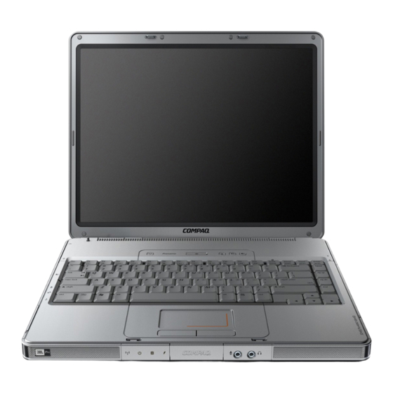
Audio-in (microphone) jack Audio-out (headphone) jack 1–6 Table 1-1 Front Components HP Pavilion ze2000 Function Produce stereo sound. On: One or more optional internal wireless devices, such as a WLAN and/or a Bluetooth® device (select models only), are turned on. - Page 11 Product Description The external components on the front of the Compaq Presario M2000 notebook are shown below and described in Table 1-2. Front Components, Compaq Presario M2000 Maintenance and Service Guide 1–7...
- Page 12 Audio-in (microphone) jack Audio-out (headphone) jack 1–8 Table 1-2 Front Components Compaq Presario M2000 Function Produce stereo sound. On: One or more optional internal wireless devices, such as a WLAN and/or a Bluetooth device (select models only), are turned on.
- Page 13 Product Description The external components on the right side of the HP Pavilion ze2000 notebook are shown below and described in Table 1-3. Right-Side Components, HP Pavilion ze2000 Maintenance and Service Guide 1–9...
- Page 14 S-Video-out jack (select models only) Security cable slot 1–10 Table 1-3 Right-Side Components HP Pavilion ze2000 Function Connect an optional USB device. Supports an optional digital memory card. Connects an optional 1394a device such as a scanner, digital camera, or digital camcorder.
- Page 15 Product Description The external components on the right side of the Compaq Presario M2000 notebook are shown below and described in Table 1-4. Right-Side Components, Compaq Presario M2000 Maintenance and Service Guide 1–11...
- Page 16 S-Video-out jack (select models only) Security cable slot 1–12 Table 1-4 Right-Side Components Compaq Presario M2000 Function Connect optional USB devices. Supports an optional digital memory card. Connects an optional 1394a device such as a scanner, digital camera, or digital camcorder.
- Page 17 Product Description The external components on the left side of the HP Pavilion ze2000 notebook are shown below and described in Table 1-5. Left-Side Components, HP Pavilion ze2000 Maintenance and Service Guide 1–13...
- Page 18 *The notebook has only one expansion port. The term expansion port 2 describes the type of expansion port. 1–14 Table 1-5 Left-Side Components HP Pavilion ze2000 Function Connects an AC adapter cable. Connects an optional VGA monitor or projector. Connects the notebook to an optional docking device.
- Page 19 Product Description The external components on the left side of the Compaq Presario M2000 notebook are shown below and described in Table 1-6. Left-Side Components, Compaq Presario M2000 Maintenance and Service Guide 1–15...
- Page 20 *The notebook has only one expansion port. The term expansion port 2 describes the type of expansion port. 1–16 Table 1-6 Left-Side Components Compaq Presario M2000 Function Connects an AC adapter cable. Connects an optional VGA monitor or projector. Connects the notebook to an optional docking device.
-
Page 21: Rear Panel Components
The external components on the rear panel of the HP Pavilion ze2000 notebook are shown below and described in Table 1-7. Rear Panel Components, HP Pavilion ze2000 Item Component Battery bay Exhaust vent Maintenance and Service Guide Table 1-7 Rear Panel Components... - Page 22 Product Description The external components on the rear panel of the Compaq Presario M2000 notebook are shown below and described in Table 1-8. Rear Panel Components, Compaq Presario M2000 Item Component Battery bay Exhaust vent 1–18 Table 1-8 Rear Panel Components...
- Page 23 Product Description The notebook keyboard components on the HP Pavilion ze2000 notebook are shown below and described in Table 1-9. Keyboard Components, HP Pavilion ze2000 Maintenance and Service Guide 1–19...
-
Page 24: Keyboard Components
Keypad keys (15) num lock key 1–20 Table 1-9 Keyboard Components HP Pavilion ze2000 Function Perform system and application tasks. When combined with the fn key, several keys perform additional tasks as hotkeys. Enables caps lock and turns on the caps lock light. - Page 25 Product Description The notebook keyboard components on the Compaq Presario M2000 notebook are shown below and described in Table 1-10. Keyboard Components, Compaq Presario M2000 Maintenance and Service Guide 1–21...
- Page 26 Arrow keys Keypad keys (15) num lock key 1–22 Table 1-10 Keyboard Components Compaq Presario M2000 Function Perform system and application tasks. When combined with the Fn key, the function keys perform additional tasks as hotkeys. Enables caps lock and turns on the caps lock light.
-
Page 27: Top Components
The notebook top components on the HP Pavilion ze2000 notebook are shown below and described in Table 1-11. Top Components, HP Pavilion ze2000 Item Component Left and right TouchPad buttons TouchPad Caps lock light Display switch Maintenance and Service Guide... - Page 28 Product Description HP Pavilion ze2000 (Continued) Item Component Power/standby button Volume down button Volume mute button Mute light Volume up button Wireless button (select models only) Num lock light 6-in-1 Digital Media Reader light (select models only) TouchPad vertical scrolling region 1–24...
- Page 29 The top components on the Compaq Presario M2000 notebook are shown below and described in Table 1-12. Top Components, Compaq Presario M2000 Item Component Left and right TouchPad buttons TouchPad Caps lock light Display switch Maintenance and Service Guide Table 1-12...
- Page 30 Product Description Compaq Presario M2000 (Continued) Item Component Wireless light (available on select models) Power/standby button Volume down button Volume up button Volume mute button Mute light Num lock light 6-in-1 Memory Reader light (select models only) TouchPad vertical and...
-
Page 31: Bottom Components
The external components on the bottom of the HP Pavilion ze2000 notebook are shown below and described in Table 1-13. Bottom Components, HP Pavilion ze2000 Item Component Battery bay Battery pack release latch Memory module compartment Maintenance and Service Guide... - Page 32 Product Description HP Pavilion ze2000 (Continued) Item Component Exhaust vents (4) Optical drive Label area Mini PCI compartment Hard drive bay 1–28 Table 1-13 Bottom Components Function Provide airflow to cool internal components. Ä To prevent overheating, do not obstruct vents. Do not allow a...
- Page 33 The external components on the bottom of the Compaq Presario M2000 notebook are shown below and described in Table 1-14. Bottom Components, Compaq Presario M2000 Item Component Battery bay Battery pack release latch Memory module compartment Maintenance and Service Guide...
- Page 34 Product Description Compaq Presario M2000 (Continued) Item Component Exhaust vents (4) Optical drive Label area Mini PCI compartment Hard drive bay 1–30 Table 1-14 Bottom Components Function Provide airflow to cool internal components. Ä To prevent overheating, do not obstruct vents. Do not allow a...
-
Page 35: Design Overview
1.5 Design Overview This section presents a design overview of key parts and features of the notebook. Refer to to identify replacement parts, and Replacement Procedures,” The system board provides the following device connections: ■ Memory module ■ Mini PCI communications devices ■... -
Page 36: Computer Setup
Å WARNING: Only authorized technicians trained by HP should repair this equipment. All troubleshooting and repair procedures are detailed to allow only subassembly-/module-level repair. Because of the complexity of the individual boards and subassemblies, do not attempt to make repairs at the component level or modifications to any printed wiring board. -
Page 37: Selecting From The Main Menu
Troubleshooting 2. Select the Main, Security, Advanced, or Tools menu. 3. To close Computer Setup and restart the notebook: ❏ Select Exit > Exit Saving Changes, and then press – or – ❏ Select Exit > Exit Discarding Changes, and then press –... -
Page 38: Selecting From The Security Menu
Selecting from the Security Menu Select Administrator Password Power-on Password DriveLock Passwords Password Options (Password options can be selected only when a power-on password has been set.) Device Security *Not applicable to SuperDisk LS-120 drives. Maintenance and Service Guide Table 2-2 Security Menu To Do This Enter, change, or delete an Administrator... -
Page 39: Selecting From The Advanced Menu
Troubleshooting Selecting from the Advanced Menu Select Language Boot Order Accessibility Options Video Memory Selecting from the Tools Menu Select Hard Drive Self Test 2–4 Table 2-3 Advanced Menu To Do This Change the Computer Setup language. Enable/disable MultiBoot, which sets a startup sequence that can include most bootable devices and media in the system. -
Page 40: Troubleshooting Flowcharts
2.2 Troubleshooting Flowcharts Troubleshooting Flowcharts Overview Flowchart Description “Flowchart 2.1—Initial Troubleshooting” “Flowchart 2.2—No Power, Part 1” “Flowchart 2.3—No Power, Part 2” “Flowchart 2.4—No Power, Part 3” “Flowchart 2.5—No Power, Part 4” “Flowchart 2.6—No Video, Part 1” “Flowchart 2.7—No Video, Part 2” “Flowchart 2.8—Nonfunctioning Docking Device (if applicable)”... - Page 41 Troubleshooting Troubleshooting Flowcharts Overview (Continued) Flowchart Description 2.14 “Flowchart 2.14—No OS Loading, Optical Drive” 2.15 “Flowchart 2.15—No Audio, Part 1” 2.16 “Flowchart 2.16—No Audio, Part 2” 2.17 “Flowchart 2.17—Nonfunctioning Device” 2.18 “Flowchart 2.18—Nonfunctioning Keyboard” 2.19 “Flowchart 2.19—Nonfunctioning Pointing Device” 2.20 “Flowchart 2.20—No Network/Modem Connection”...
-
Page 42: Flowchart 2.1—Initial Troubleshooting
Flowchart 2.1—Initial Troubleshooting Begin troubleshooting. Is there power? Beeps, LEDs, or error messages? Is there video? (no boot) Is the OS loading? Is there sound? Maintenance and Service Guide Go to “Flowchart 2.2—No Power, Part 1.” Check LED board, speaker connections. -
Page 43: Flowchart 2.2—No Power, Part
Troubleshooting Flowchart 2.2—No Power, Part 1 No power (power LED is off). Remove from docking device (if applicable). Power up on battery power? Power up on AC power? Power up in docking device? 1. Reseat the power cables in the docking device and at the AC outlet. -
Page 44: Flowchart 2.3—No Power, Part
Flowchart 2.3—No Power, Part 2 Continued from “Flowchart 2.2—No Power, Part 1.” Visually check for debris in battery socket and clean if necessary. Power on? Check battery by recharging it, moving it to another notebook, or replacing it. Power on? Done Maintenance and Service Guide Done... -
Page 45: Flowchart 2.4—No Power, Part
Troubleshooting Flowchart 2.4—No Power, Part 3 Continued from “Flowchart 2.3—No Power, Part 2.” Plug directly into AC outlet. Power LED Reseat AC adapter in notebook and at power source. Power on? Power outlet active? Replace power cord. Power on? 2–10 Done Done Internal or... -
Page 46: Flowchart 2.5—No Power, Part
Flowchart 2.5—No Power, Part 4 Continued from “Flowchart 2.4—No Power, Part 3.” Open notebook. Loose or damaged parts? Close notebook and retest. Power on? Done Maintenance and Service Guide Reseat loose components and boards and replace damaged items. Replace the following items (if applicable). Check notebook operation after each replacement: 1. -
Page 47: Flowchart 2.6—No Video, Part
Troubleshooting Flowchart 2.6—No Video, Part 1 No video. Docking Device Stand-alone or docking device? Stand-alone Internal or external display*? Internal External Adjust brightness. Video OK? Replace the following one at a time. Test after each replacement. Check for bent pins on cable. Video OK? Done 2–12... -
Page 48: Flowchart 2.7—No Video, Part
Flowchart 2.7—No Video, Part 2 Continued from “Flowchart 2.6—No Video, Part 1.” Remove notebook from docking device, if connected. Adjust display brightness. Video OK? Check that notebook is properly seated in docking device, for bent pins on cable, and for monitor connection. -
Page 49: Flowchart 2.8-Nonfunctioning Docking Device (If Applicable)
Troubleshooting Flowchart 2.8—Nonfunctioning Docking Device (if applicable) Nonfunctioning docking device. Reseat power cord in docking device and power outlet. Check voltage setting on docking device. Reset monitor cable connector at docking device. Docking device operating? Remove notebook, reseat all internal parts, and replace any damaged items in docking device. -
Page 50: Flowchart 2.9—No Operating System (Os) Loading
Flowchart 2.9—No Operating System (OS) Loading No OS loading.* Reseat power cord in docking device and power outlet. *NOTE: Before beginning troubleshooting, always check cable connections, cable ends, and drives for bent or damaged pins. Maintenance and Service Guide No OS loading from hard drive, go to “Flowchart 2.10—No OS Loading, Hard Drive, Part 1.”... -
Page 51: Flowchart 2.10-No Os Loading, Hard Drive
Troubleshooting Flowchart 2.10—No OS Loading, Hard Drive, Part 1 OS not loading from hard drive. Nonsystem disk message? Reseat external hard drive. OS loading? Boot from Check the Setup utility for correct booting order. Boot from hard drive? Done 2–16 Go to “Flowchart 2.11—No OS Loading,... -
Page 52: Flowchart 2.11-No Os Loading, Hard Drive
Flowchart 2.11—No OS Loading, Hard Drive, Part 2 Continued from “Flowchart 2.10—No OS Loading, Hard Drive, Part 1.” 1. Replace CD or diskette in 2. Replace drive? Remove diskette and reboot. Boot from hard drive? Boot from diskette drive? Loading, Diskette Hard drive accessible? Go to... -
Page 53: Flowchart 2.12-No Os Loading, Hard Drive
Troubleshooting Flowchart 2.12—No OS Loading, Hard Drive, Part 3 Continued from “Flowchart 2.11—No OS Loading, Hard Drive, Part 2.” System files on hard drive? Virus hard drive? Run SCANDISK and check for bad sectors. Can bad sectors be fixed? Fix bad sectors. -
Page 54: Flowchart 2.13—No Os Loading, Diskette Drive
Flowchart 2.13—No OS Loading, Diskette Drive OS not loading from diskette drive. Nonsystem disk message? Boot from another device? Diskette drive enabled in the Setup utility? Is diskette drive boot order correct? Change boot priority using the Setup utility. Maintenance and Service Guide Reseat diskette drive. -
Page 55: Flowchart 2.14-No Os Loading, Optical Drive
Troubleshooting Flowchart 2.14—No OS Loading, Optical Drive No OS loading from CD-ROM or DVD-ROM drive. Boots from CD or DVD? Reseat drive. 2–20 Disc in drive? Install bootable disc. bootable disc. Done Boots from CD or DVD? Booting from another 2.17—Nonfunctioning device? Reset the notebook. -
Page 56: Flowchart 2.15-No Audio, Part
Flowchart 2.15—No Audio, Part 1 No audio. Notebook in docking device (if applicable)? Go to “Flowchart 2.16—No Audio, Part 2.” 2.17—Nonfunctioning Maintenance and Service Guide Turn up audio internally or externally. Undock Replace the following docking device components one at a time, as applicable. Check audio status after each change. -
Page 57: Flowchart 2.16-No Audio, Part
Troubleshooting Flowchart 2.16—No Audio, Part 2 Continued from “Flowchart 2.15—No Audio, Part 1.” Audio driver in OS configured? Correct drivers for application? Connect to external speaker. Audio? 2–22 Reload audio drivers. Load drivers and set configuration in OS. Replace audio board and speaker connections... -
Page 58: Flowchart 2.17-Nonfunctioning Device
Flowchart 2.17—Nonfunctioning Device Unplug the nonfunctioning device from the notebook and inspect cables and plugs for bent or broken pins Clear CMOS. Reattach device. Close notebook, plug in power, and reboot. Device boots properly? Done Maintenance and Service Guide Nonfunctioning device. -
Page 59: Flowchart 2.18-Nonfunctioning Keyboard
Troubleshooting Flowchart 2.18—Nonfunctioning Keyboard Keyboard not operating properly. Connect notebook to good external keyboard. External device works? Reseat internal keyboard connector (if applicable). Done 2–24 Replace system board. Replace internal keyboard or cable. Replace system board. Done Maintenance and Service Guide... -
Page 60: Flowchart 2.19-Nonfunctioning Pointing Device
Flowchart 2.19—Nonfunctioning Pointing Device Pointing device not operating properly. Connect notebook to good external pointing device. External device works? Reseat internal pointing device connector (if applicable). Done Maintenance and Service Guide Replace system board. Replace internal pointing device or cable. Replace system board. -
Page 61: Flowchart 2.20-No Network/Modem Connection
Troubleshooting Flowchart 2.20—No Network/Modem Connection No network or modem connection. Network or modem jack active? Digital line? NIC/modem configured in OS? Disconnect all power from the notebook and open. Reseat NIC/modem (if applicable). 2–26 Replace jack or have jack activated. Connect to nondigital line. -
Page 62: Illustrated Parts Catalog
Illustrated Parts Catalog This chapter provides an illustrated parts breakdown and a reference for spare part numbers and option part numbers. 3.1 Serial Number Location When ordering parts or requesting information, provide the notebook serial number and model number located on the bottom of the notebook. -
Page 63: Notebook Major Components
Illustrated Parts Catalog 3.2 Notebook Major Components Notebook Major Components, HP Pavilion ze2000 3–2 Maintenance and Service Guide... - Page 64 Spare Parts: Notebook Major Components Item Description Display assemblies (include wireless antenna boards and cables) 15.0-inch, XGA TFT, for use on HP Pavilion ze2000 models 15.0-inch, XGA TFT, for use on Compaq Presario M2000 models Display hinge brackets (not illustrated)
- Page 65 Illustrated Parts Catalog Notebook Major Components, Compaq Presario M2000 3–4 Maintenance and Service Guide...
- Page 66 French Canada Germany Greece Israel Italy Korea Latin America Europe and the Netherlands Norway Portugal For use on Compaq Presario M2000 models in: Denmark France French Canada International Italy Korea Latin America Maintenance and Service Guide Table 3-1 367778-A41 Saudi Arabia...
- Page 67 Illustrated Parts Catalog Notebook Major Components, HP Pavilion ze2000 3–6 Maintenance and Service Guide...
- Page 68 Spare Parts: Notebook Major Components (Continued) Item Description Top covers (include TouchPad) For use on HP Pavilion ze2000 models with full-featured models For use on HP Pavilion ze2000 models with defeatured models For use on Compaq M2000 models with full-featured models...
- Page 69 Illustrated Parts Catalog Notebook Major Components, Compaq Presario M2000 3–8 Maintenance and Service Guide...
- Page 70 For use on models with full-featured models For use on models with defeatured models Base enclosures For use on HP Pavilion ze2000 models For use on Compaq Presario M2000 models Hard drives (all 4200-rpm, include frame and connector) 80 GB 60 GB...
- Page 71 Illustrated Parts Catalog Notebook Major Components, HP Pavilion ze2000 3–10 Maintenance and Service Guide...
- Page 72 For use on HP Pavilion ze2000 models 8X DVD-ROM drive 24X DVD/CD-RW Combo Drive 8X DVD±RW/R and CD-RW Combo Drive For use on Compaq Presario M2000 models 8X DVD-ROM drive 24X DVD/CD-RW Combo Drive 8X DVD±RW/R and CD-RW Combo Drive...
-
Page 73: Miscellaneous Plastics Kit
Illustrated Parts Catalog 3.3 Miscellaneous Plastics Kit Miscellaneous Plastics Kit 3–12 Maintenance and Service Guide... - Page 74 Spare Part Number Information Item Description Miscellaneous Plastics Kit For use on HP Pavilion ze2000 models For use on Compaq Presario M2000 models Includes: Memory module compartment cover Mini PCI compartment cover Hard drive cover PC Card slot space saver...
-
Page 75: Mass Storage Devices
Illustrated Parts Catalog 3.4 Mass Storage Devices Mass Storage Devices 3–14 Maintenance and Service Guide... - Page 76 For use on HP Pavilion ze2000 models 8X DVD-ROM Drive 24X DVD/CD-RW Combo Drive 8X DVD±RW/R and CD-RW Combo Drive For use on Compaq Presario M2000 models 8X DVD-ROM Drive 24X DVD/CD-RW Combo Drive 8X DVD±RW/R and CD-RW Combo Drive...
-
Page 77: Miscellaneous
Spare Parts: Miscellaneous (not illustrated) Description Logo Kits For use on HP Pavilion ze2000 models For use on Compaq Presario M2000 models Remote control (for use only on HP ze2000 notebook models) USB travel mouse Notebook entertainment cable and Y-cable 65-watt AC adapter Screw Kit (includes the following screws;... - Page 78 Spare Parts: Miscellaneous (not illustrated) (Continued) Description Power cords For use in: Australia and New Zealand Belgium, Europe, Finland, France, Germany, Greece, the Netherlands, Norway, Portugal, Spain, and Sweden Brazil Canada, French Canada, Latin America, Taiwan, Thailand, and the United States Denmark Hong Kong and the United Kingdom Israel...
-
Page 79: Sequential Part Number Listing
Battery pack, 12-cell, 8.8-AHr 367771-001 Processor, Intel Pentium M 725 (1.6-GHz) with 400-MHz FSB (includes thermal pad) 367777-001 Keyboard for use on Compaq Presario M2000 models in the United States 367777-021 Keyboard for use on Compaq Presario M2000 international models... - Page 80 367777-281 Keyboard for use on Compaq Presario M2000 models in Thailand 367777-AB1 Keyboard for use on Compaq Presario M2000 models in Taiwan 367777-AD1 Keyboard for use on Compaq Presario M2000 models in Korea 367777-B71 Keyboard for use on Compaq Presario M2000 models in...
- Page 81 Keyboard for use on HP Pavilion ze2000 models in Brazil 367778-281 Keyboard for use on HP Pavilion ze2000 models in Thailand 367778-331 Keyboard for use on HP Pavilion ze2000 models in Europe and the Netherlands 367778-A41 Keyboard for use on HP Pavilion ze2000 models in Belgium...
- Page 82 Spare Parts: Sequential Part Number Listing (Continued) Spare Part Number Description 373979-011 Power cord for use in Australia and New Zealand 373979-021 Power cord for use in Belgium, Europe, Finland, France, Germany, Greece, the Netherlands, Norway, Portugal, Spain, and Sweden 373979-031 Power cord for use in Hong Kong and the United Kingdom 373979-061...
- Page 83 Hard drive, 4200-rpm, 60-GB (includes frame and connector) 381398-001 Hard drive, 4200-rpm, 80-GB (includes frame and connector) 381399-001 8X DVD-ROM Drive for use on HP Pavilion ze2000 models (includes bezel) 381400-001 8X DVD-ROM Drive for use on Compaq Presario M2000...
- Page 84 Spare Parts: Sequential Part Number Listing (Continued) Spare Part Number Description 382397-001 Top cover for use on Compaq M2000 models with full-featured models (includes TouchPad) 382398-001 Base enclosure for use on HP Pavilion ze2000 models 382399-001 Base enclosure for use on Compaq Presario M2000 models...
- Page 85 USB/S-Video controller board 382417-001 Display hinge brackets for use on HP Pavilion ze2000 models 382418-001 Hinge covers (for use only on Compaq Presario M2000 models) 382905-001 Top cover for use on HP Pavilion ze2000 models with defeatured models (includes TouchPad)
-
Page 86: Removal And Replacement Preliminaries
Removal and Replacement This chapter provides essential information for proper and safe removal and replacement service. 4.1 Tools Required You will need the following tools to complete the removal and replacement procedures: ■ Magnetic driver ■ Phillips P0 driver ■ 5.0-mm socket for system board locks ■... -
Page 87: Service Considerations
Removal and Replacement Preliminaries 4.2 Service Considerations The following sections include some of the considerations that you should keep in mind during disassembly and assembly procedures. ✎ As you remove each subassembly from the notebook, place the subassembly (and all accompanying s) away from the work area to prevent damage. -
Page 88: Preventing Damage To Removable Drives
4.3 Preventing Damage to Removable Drives Removable drives are fragile components that must be handled with care. To prevent damage to the notebook, damage to a removable drive, or loss of information, observe the following precautions: ■ Before removing or inserting a hard drive, shut down the notebook. -
Page 89: Preventing Electrostatic Damage
Removal and Replacement Preliminaries 4.4 Preventing Electrostatic Damage Many electronic components are sensitive to electrostatic discharge (ESD). Circuitry design and structure determine the degree of sensitivity. Networks built into many integrated circuits provide some protection, but in many cases, the discharge contains enough power to alter device parameters or melt silicon junctions. -
Page 90: Packaging And Transporting Precautions
4.5 Packaging and Transporting Precautions Use the following grounding precautions when packaging and transporting equipment: ■ To avoid hand contact, transport products in static-safe containers, such as tubes, bags, or boxes. ■ Protect all electrostatic-sensitive parts and assemblies with conductive or approved containers or packaging. ■... -
Page 91: Workstation Precautions
Removal and Replacement Preliminaries 4.6 Workstation Precautions Use the following grounding precautions at workstations: ■ Cover the workstation with approved static-shielding material (refer to ■ Use a wrist strap connected to a properly grounded work surface and use properly grounded tools and equipment. ■... - Page 92 Other grounding equipment recommended for use in preventing electrostatic damage includes: ■ Antistatic tape ■ Antistatic smocks, aprons, and sleeve protectors ■ Conductive bins and other assembly or soldering aids ■ Nonconductive foam ■ Conductive tabletop workstations with ground cords of one megohm resistance ■...
-
Page 93: Typical Electrostatic Voltage Levels
Removal and Replacement Preliminaries Table 4-1 shows how humidity affects the electrostatic voltage levels generated by different activities. Typical Electrostatic Voltage Levels Event Walking across carpet Walking across vinyl floor Motions of bench worker Removing DIPS from plastic tube Removing DIPS from vinyl tray Removing DIPS from Styrofoam Removing bubble pack from PCB Packing PCBs in foam-lined box... -
Page 94: Removal And Replacement Procedures
Removal and Replacement This chapter provides removal and replacement procedures. There are 61 screws, in 10 different sizes, that must be removed, replaced, or loosened when servicing the notebook. Make special note of each screw size and location during removal and replacement. -
Page 95: Serial Number
Removal and Replacement Procedures 5.1 Serial Number Report the notebook serial number to HP when requesting information or ordering spare parts. The serial number is located on the bottom of the notebook. Serial Number Location 5–2 Maintenance and Service Guide... -
Page 96: Disassembly Sequence Chart
5.2 Disassembly Sequence Chart Use the chart below to determine the section number to be referenced when removing notebook components. Disassembly Sequence Chart Section Description Preparing the notebook for disassembly Battery pack Hard drive Notebook feet Optical drive Memory module Mini PCI communications card Ä... - Page 97 5.21 System board 5–4 # of Screws Removed HP Pavilion ze2000 = 4 Compaq Presario M2000 = 6 HP Pavilion ze2000 = 23 Compaq Presario M2000 = 21 HP Pavilion ze2000 = 2 Compaq Presario M2000 = 3 Maintenance and Service Guide...
-
Page 98: Preparing The Notebook For Disassembly
5.3 Preparing the Notebook for Disassembly Before you begin any removal or installation procedures: 1. Shut down the notebook. If you are unsure whether the notebook is off or in hibernation, turn the computer on, and then shut it down through the operating system. 2. - Page 99 Removal and Replacement Procedures Battery Pack Spare Part Number Information 12-cell, 8.8-AHr 6-cell, 4.4-AHr 4. Remove the battery pack by following these steps: a. Turn the notebook upside down with the front panel toward you. b. Slide and hold the battery release latch 1 to the left. (The front edge of the battery pack disengages from the notebook.) c.
- Page 100 ✎ The hard drive cover is included in the Miscellaneous Plastics Kits, spare part numbers 382400-001 (for use on HP Pavilion ze2000 models) and 382401-001 (for use on Compaq Presario M2000 models). Removing the Hard Drive Cover Maintenance and Service Guide...
- Page 101 Removal and Replacement Procedures e. Use the mylar tab 1 on the right side of the hard drive to lift the right side of the hard drive until it disconnects from the notebook. f. Lift the hard drive straight up 2 and remove it from the hard drive bay.
- Page 102 g. Remove the 4 silver PM2.5×4.0 screws 1 that secure the hard drive frame to the hard drive. h. Lift the frame up 2 to remove if from the hard drive. i. Slide the hard drive connector 3 toward you and remove it.
-
Page 103: Notebook Feet
Miscellaneous Plastics Kits, spare part numbers 382400-001 (for use on HP Pavilion ze2000 models) and 382401-001 (for use on Compaq Presario M2000 models). The feet attach to the base enclosure as illustrated below. Replacing the Notebook Feet 5–10... -
Page 104: Optical Drive
For use on HP Pavilion ze2000 models 8X DVD-ROM Drive 24X DVD/CD-RW Combo Drive 8X DVD±RW/R and CD-RW Combo Drive For use on Compaq Presario M2000 models 8X DVD-ROM Drive 24X DVD/CD-RW Combo Drive 8X DVD±RW/R and CD-RW Combo Drive 24X CD-ROM Drive 1. - Page 105 3. Remove the black PM2.0×6.0 screw 1 that secures the optical drive to the notebook. ✎ The Compaq Presario M2000 optical drive is secured by one black PM2.0×7.0 screw. 4. Insert a thin tool, such as a paper clip, into the media tray release hole 2.
-
Page 106: Memory Module
5.6 Memory Module Memory Module Spare Part Number Information 512-MB 256-MB 1. Prepare the notebook for disassembly (refer to Maintenance and Service Guide Removal and Replacement Procedures Section 381395-001 381394-001 5.3). 5–13... - Page 107 ✎ The memory module compartment cover is included in the Miscellaneous Plastics Kits, spare part numbers 382400-001 (for use on HP Pavilion ze2000 models) and 382401-001 (for use on Compaq Presario M2000 models). Removing the Memory Module Compartment Cover 5–14...
- Page 108 5. Spread the retaining tabs 1 on each side of the memory module socket to release the memory module. (The right side of the module rises away from the notebook.) 6. Slide the module away from the socket at an angle 2. ✎...
-
Page 109: Mini Pci Communications Card
Removal and Replacement Procedures 5.7 Mini PCI Communications Card Mini PCI Communications Card Spare Part Number Information 802.11b/g Broadcomm (MOW) 802.11b/g Broadcomm (ROW) 802.11b Intel (MOW) 802.11b Intel (ROW) 802.11b/g Intel (MOW) 802.11b/g Intel (ROW) 1. Prepare the notebook for disassembly 5–16 373047-001 373048-001... - Page 110 ✎ The Mini PCI compartment cover is included in the Miscellaneous Plastics Kits, spare part numbers 382400-001 (for use on HP Pavilion ze2000 models) and 382401-001 (for use on Compaq Presario M2000 models). Removing the Mini PCI Compartment Cover Maintenance and Service Guide Removal and Replacement Procedures 5–17...
- Page 111 Removal and Replacement Procedures ✎ Before disconnecting the cables, make note of which wireless antenna cable is attached to which antenna clip on the Mini PCI communications card. 5. Disconnect the wireless antenna cables 1 from the Mini PCI communications card. 6.
-
Page 112: Keyboard Cover
5.8 Keyboard Cover Keyboard Cover Spare Part Number Information For use on HP Pavilion ze2000 models with wireless capability (includes wireless button and light) For use on HP Pavilion ze2000 models without wireless capability (includes wireless button and light) For use on Compaq Presario M2000 models with wireless... - Page 113 Removal and Replacement Procedures 3. Remove the 2 silver PM2.0×5.0 screws that secure the keyboard cover to the notebook. Removing the Keyboard Cover Screws 5–20 Maintenance and Service Guide...
- Page 114 4. Turn the notebook display-side up with the front panel toward you. 5. Open the notebook as far as possible. 6. Insert a flat blade tool into the keyboard cover notches behind keyboard cover disengages from the notebook. 7. Remove the keyboard cover. Removing the Keyboard Cover Reverse the above procedure to install the keyboard cover.
-
Page 115: Led Board
Removal and Replacement Procedures 5.9 LED Board LED Board Spare Part Number Information For use on HP Pavilion ze2000 models For use on Compaq Presario M2000 models 1. Prepare the notebook for disassembly 2. Remove the keyboard cover 5–22 382415-001... - Page 116 3. Release the zero insertion force (ZIF) connector to which the keyboard cable is connected and disconnect the keyboard cable 1 from the system board. 4. Remove the 2 silver PM2.0×3.0 screws 2 that secure the LED board to the notebook. 5.
-
Page 117: Keyboard
Germany Greece Israel Italy Korea Latin America Europe and the Netherlands Norway For use on Compaq Presario M2000 models in: Denmark France French Canada International Italy Korea Latin America 1. Prepare the notebook for disassembly 2. Remove the keyboard cover 5–24... - Page 118 Removal and Replacement Procedures 3. Remove the 3 black PM2.0×4.0 screws 1 and the black PM2.0×6.0 screw 2 that secure the keyboard to the notebook. Removing the Keyboard Screws Maintenance and Service Guide 5–25...
- Page 119 Removal and Replacement Procedures 4. Lift the rear edge of the keyboard and swing it toward you until it rests on the palm rest. Releasing the Keyboard 5–26 Maintenance and Service Guide...
- Page 120 5. Release the zero insertion force (ZIF) connector 1 to which the keyboard cable is connected and disconnect the keyboard cable 2 from the system board. 6. Remove the keyboard. Disconnecting the Keyboard Cable Reverse the above procedure to install the keyboard. Maintenance and Service Guide Removal and Replacement Procedures 5–27...
-
Page 121: Display Assembly
Removal and Replacement Procedures 5.11 Display Assembly Display Assembly Spare Part Number Information 15.0-inch, XGA TFT, for use on HP Pavilion ze2000 models (includes wireless antenna boards and cables) 15.0-inch, XGA TFT, for use on Compaq Presario M2000 models (includes wireless antenna boards and cables) - Page 122 2. Turn the notebook upside down, with the front panel toward you. 3. Disconnect the wireless antenna cables from the Mini PCI communications card 1. 4. Remove the cables from the clip 2 in the base enclosure. Disconnecting and Removing the Wireless Antenna Cables Maintenance and Service Guide Removal and Replacement Procedures 5–29...
- Page 123 Removal and Replacement Procedures 5. Turn the notebook display-side up with the front toward you. 6. Open the display. 7. Disconnect the display cable from the system board 1. 8. Remove the wireless antenna cables from the clips 2 in the top cover.
- Page 124 Failure to follow this caution can result in damage to the display assembly. ✎ Steps 9 and 10 apply only to HP Pavilion ze2000 models. See steps 11 and 12 in this section for information on removing the display assembly on Compaq Presario M2000 models.
- Page 125 Failure to follow this caution can result in damage to the display assembly. ✎ Steps 11 and 12 apply only to Compaq Presario M2000 models. 11. Remove the 6 black PM2.0×6.0 screws 1 that secure the display assembly to the notebook.
-
Page 126: Base Enclosure
5.12 Base Enclosure Base Enclosure Spare Part Number Information For use on HP Pavilion ze2000 models For use on Compaq Presario M2000 models 1. Prepare the notebook for disassembly and remove the following components: a. Optical drive b. Memory module compartment cover c. - Page 127 Removal and Replacement Procedures ✎ Steps 3 through 5 apply only to HP Pavilion ze2000 models. See steps 6 through 8 in this section for information on removing the base enclosure screws on Compaq Presario M2000 models. 3. Remove the 3 black PM2.0×6.0 screws 1 and the 2 black PM2.0×4.0 screws 2 that secure the base enclosure to the...
- Page 128 2 Seven black PM2.0×6.0 screws that secure the base enclosure the notebook 3 Six silver PM2.0×5.0 screws that secure the base enclosure the notebook Removing the Base Enclosure Screws, Part 2, HP Pavilion ze2000 Models Only Maintenance and Service Guide Removal and Replacement Procedures 5–35...
- Page 129 Removal and Replacement Procedures ✎ Steps 6 through 8 apply only to Compaq Presario M2000 models. 6. Remove the 2 black PM2.0×7.0 screws 1 and the silver PM2.0×5.0 screw 2 that secure the base enclosure to the notebook. Removing the Base Enclosure Screws, Part 1, Compaq Presario M2000 Models Only 5–36...
- Page 130 8. Remove the 3 black PM2.0×4.0 screws 1 and the 15 black PM2.0×7.0 screws 2 that secure the base enclosure to the notebook. Removing the Base Enclosure Screws, Part 2, Compaq Presario M2000 Models Only Maintenance and Service Guide Removal and Replacement Procedures 5–37...
- Page 131 Removal and Replacement Procedures ✎ Steps 9 and 10 apply to both HP Pavilion ze2000 and Compaq Presario M2000 models. 9. Lift the rear edge of the base enclosure 1 until it disengages from the notebook. 10. Slide the base enclosure back 2 and remove it.
-
Page 132: Speaker Assembly
5.13 Speaker Assembly Speaker Assembly Spare Part Number Information For use on HP Pavilion ze2000 models For use on Compaq Presario M2000 models 1. Prepare the notebook for disassembly and remove the following components: a. Optical drive b. Memory module compartment cover c. - Page 133 Removal and Replacement Procedures 2. Disconnect the speaker cable 1 from the system board. 3. Lift the speaker straight up to remove it 2 from the top cover. Removing the Speaker Assembly Reverse the above procedure to install the speaker assembly. 5–40 Maintenance and Service Guide...
-
Page 134: Heat Sink
5.14 Heat Sink Heat Sink Spare Part Number Information Heat sink (includes thermal pad) 1. Prepare the notebook for disassembly and remove the following components: a. Optical drive b. Memory module compartment cover c. Mini PCI compartment cover d. Keyboard cover e. - Page 135 Removal and Replacement Procedures 3. Disconnect the fan cable 1 from the system board. 4. Remove the 3 silver PM2.0×4.0 screws 2 that secure the heat sink to the top cover. 5. Remove the heat sink 3. Removing the Heat Sink Reverse the above procedure to install the heat sink.
-
Page 136: Fan
5.15 Fan Fan Spare Part Number Information Fan (includes thermal pad) 1. Prepare the notebook for disassembly and remove the following components: a. Optical drive b. Memory module compartment cover c. Mini PCI compartment cover d. Keyboard cover e. Keyboard f. - Page 137 Removal and Replacement Procedures 3. Remove the 2 silver PM2.0×4.0 screws 1 that secure the fan to the heat sink. 4. Remove the fan 2. Removing the Fan Reverse the above procedure to install the fan. 5–44 Maintenance and Service Guide...
-
Page 138: Processor
5.16 Processor Processor Spare Part Number Information Intel Pentium M 745 (1.8-GHz) with 400-MHz FSB Intel Pentium M 735 (1.7-GHz) with 400-MHz FSB Intel Pentium M 725 (1.6-GHz) with 400-MHz FSB Intel Pentium M 715A (1.5-GHz) with 400-MHz FSB Intel Celeron M 360 (1.4-GHz) with 400-MHz FSB Intel Celeron M 350 (1.3-GHz) with 400-MHz FSB 1. - Page 139 Removal and Replacement Procedures 2. Turn the processor locking screw 1 one-quarter turn counterclockwise until you feel a click. 3. Lift the processor 2 straight up and remove it. ✎ Note that the gold triangle 3 on the processor should be aligned in the front right corner when you install the processor.
-
Page 140: Battery Connector Board
5.17 Battery Connector Board Battery Connector Board Spare Part Number Information Battery connector board 1. Prepare the notebook for disassembly and remove the following components: a. Optical drive b. Memory module compartment cover c. Mini PCI compartment cover d. Keyboard cover e. - Page 141 Removal and Replacement Procedures 3. Remove the silver PM2.0×4.0 screw that secures the battery connector board to the top cover. Removing the Battery Connector Board Screw 5–48 Maintenance and Service Guide...
- Page 142 4. Turn the top cover upside down, with the front panel toward you. 5. Remove the silver PM2.0×4.0 screw 1 that secures the battery connector board to the top cover. 6. Slide the battery connector board toward the rear panel 2 until it disconnects from the system board.
-
Page 143: Power Connector Board
Removal and Replacement Procedures 5.18 Power Connector Board Power Connector Board Spare Part Number Information Power connector board 1. Prepare the notebook for disassembly and remove the following components: a. Optical drive b. Memory module compartment cover c. Mini PCI compartment cover d. - Page 144 2. Remove the 2 silver PM2.0×4.0 screws 1 that secure the power connector board to the top cover. 3. Slide the power connector board toward the rear panel 2 until it disconnects it from the system board. 4. Remove the power connector board 3. Removing the Power Connector Board Reverse the above procedure to install the power connector board.
-
Page 145: Usb/S-Video Controller Board
Removal and Replacement Procedures 5.19 USB/S-Video Controller Board ✎ This section applies only to full-featured models. USB/S-Video Controller Board Spare Part Number Information USB/S-Video controller board 1. Prepare the notebook for disassembly and remove the following components: a. Optical drive b. - Page 146 2. Remove the 2 silver PM2.0×4.0 screws 1 that secure the USB/S-Video controller board to the top cover. 3. Lift up on the right side of the board 2 to disconnect it from the system board. 4. Remove the USB/S-Video controller board. Removing the USB/S-Video Controller Board Reverse the above procedure to install the USB/S-Video controller board.
-
Page 147: Bluetooth Board
Removal and Replacement Procedures 5.20 Bluetooth Board ✎ This section applies only to full-featured models. Bluetooth Board Spare Part Number Information Broadcomm Bluetooth board 1. Prepare the notebook for disassembly and remove the following components: a. Optical drive b. Memory module compartment cover c. - Page 148 3. Remove the 2 PM1.5×3.5 screws 1 that secure the Bluetooth board to the USB/S-Video controller board. 4. Disconnect the Bluetooth board cable 2 from the USB/S-Video controller board. 5. Remove the Bluetooth board 3. Removing the Bluetooth Board Reverse the above procedure to install the Bluetooth board. Maintenance and Service Guide Removal and Replacement Procedures 5–55...
-
Page 149: System Board
Removal and Replacement Procedures 5.21 System Board System Board Spare Part Number Information For use on models with full-featured models (includes a disk cell RTC battery) For use on models with defeatured models (includes a disk cell RTC battery) ✎ All system board spares kits include a disk cell RTC battery. - Page 150 1. Prepare the notebook for disassembly remove the following components: a. Optical drive b. Keyboard cover c. Keyboard d. Display assembly e. Base enclosure f. Speaker assembly g. Battery connector board h. Power connector board i. USB/S-Video controller board 2. Turn the top cover top-side up, with the front panel toward you.
- Page 151 Removal and Replacement Procedures 3. Release the ZIF connector 1 to which the TouchPad cable is connected and disconnect the cable 2 from the system board. Disconnecting the TouchPad Cable 5–58 Maintenance and Service Guide...
- Page 152 4. Turn the top cover upside down with the front toward you. ✎ Step 5 applies only to HP Pavilion ze2000 models. See step 6 in this section for information on removing the system board screws on Compaq Presario M2000 models.
- Page 153 Removal and Replacement Procedures ✎ Step 6 applies only to Compaq Presario M2000 models. 6. Remove the 3 silver PM2.0×4.0 screws that secure the system board to the top cover. Removing the System Board Screws, Compaq Presario M2000 Models Only 5–60...
- Page 154 7. Flex the left edge of the top cover out 1 until the 1394 connector 2 disengages from the top cover. 8. Lift the left side of the system board 3 until the 1394 connector is clear. 9. Flex the front edge of the top cover 4 until the audio connectors 5 and LED section 6 of the system board disengage from the top cover.
- Page 155 Removal and Replacement Procedures 10. Slide the system board to the left at an angle and remove it. Removing the System Board Reverse the above procedure to install the system board. 5–62 Maintenance and Service Guide...
-
Page 156: Specifications
This chapter provides physical and performance specifications. Dimensions HP Pavilion ze2000 Height (varies from front to back) Width Depth Compaq Presario M2000 Height (varies from front to back) Width Depth Weight (varies by configuration) HP Pavilion ze2000 Compaq Presario M2000... - Page 157 Specifications Temperature Operating Nonoperating Relative humidity (noncondensing) Operating Nonoperating Maximum altitude (unpressurized) Operating (14.7 to 10.1 psia) Nonoperating (14.7 to 4.4 psia) Shock Operating Nonoperating Random Vibration Operating Nonoperating ✎ Applicable product safety standards specify thermal limits for plastic surfaces. The notebook operates well within this range of temperatures. 6–2 Table 6-1 Notebook (Continued)
- Page 158 Dimensions Height Width Diagonal Number of colors Contrast ratio Brightness Pixel resolution Pitch Format Configuration Backlight Character display Total power consumption Viewing angle Maintenance and Service Guide Table 6-2 15.0-inch, XGA, Display 22.9 cm 30.0 cm 38.1 cm Up to 16.8 million 250:1 150 nits typical 0.264 ×...
-
Page 159: Hard Drives
Specifications Dimensions Height Width Weight Interface type Transfer rate Synchronous (maximum) Security Seek times (typical read, including setting) Single track Average Maximum † Logical blocks Disk rotational speed Operating temperature ✎ Certain restrictions and exclusions apply. Consult Customer Care for details. *1 GB = 1 billion bytes when referring to hard drive storage capacity. - Page 160 Primary 6-cell, Li-Ion Battery Pack Dimensions Height Width Depth Weight Energy Voltage Amp-hour capacity Watt-hour capacity Temperature Operating Nonoperating Maintenance and Service Guide Table 6-4 2.00 cm 9.40 cm 13.40 cm 0.34 kg 11.1 V 4.4 Ah 48 Wh 5°C to 45°C 0°C to 60°C Specifications 0.79 in...
-
Page 161: Dvd/Cd-Rw Combo Drive
Specifications 24X DVD/CD-RW Combo Drive Applicable disk Center hole diameter Disk diameter Standard disc Mini disc 6–6 Table 6-5 Read: DVD-R, DVD-RW, DVD-ROM (DVD-5, DVD-9, DVD-10, DVD-18), CD-ROM (Mode 1 and 2) CD Digital Audio CD-XA ready (Mode 2, Form 1 and 2) CD-I ready (Mode 2, Form 1 and 2) CD-R, CD-RW... - Page 162 24X DVD/CD-RW Combo Drive (Continued) Disk thickness Track pitch Access time Random Full stroke Audio output level Cache buffer Data transfer rate CD-R (24X) CD-RW (10X) CD-ROM (24X) DVD (8X) Multiword DMA mode 2 Startup time Stop time Maintenance and Service Guide Table 6-5 1.2 mm (0.047 in) 0.74 µm...
- Page 163 Specifications 8X DVD±RW/R and CD-RW Combo Drive Applicable disk Center hole diameter Disk diameter Standard disc Mini disc 6–8 Table 6-6 Read: DVD-R, DVD-RW, DVD-ROM (DVD-5, DVD-9, DVD-10, DVD-18), CD-ROM (Mode 1 and 2) CD Digital Audio CD-XA ready (Mode 2, Form 1 and 2) CD-I ready (Mode 2, Form 1 and 2)
- Page 164 8X DVD±RW/R and CD-RW Combo Drive (Continued) Disk thickness Track pitch Access time Random Full stroke Audio output level Cache buffer Data transfer rate CD-R (16X) CD-RW (8X) CD-ROM (24X) DVD (8X) DVD-R (4X) DVD-RW (2X) Multiword DMA mode 2 Startup time Stop time Maintenance and Service Guide...
-
Page 165: Dvd-Rom Drive
Specifications Applicable disk Center hole diameter Disk diameter Standard disc Mini disc Disk thickness 6–10 Table 6-7 8X DVD-ROM Drive DVD-ROM (DVD-5, DVD-9, DVD-10, DVD-18) CD-ROM (Mode 1 and 2) CD Digital Audio CD-XA ready (Mode 2, Form 1 and 2) CD-I ready (Mode 2, Form 1 and 2) CD-R CD-RW... - Page 166 8X DVD-ROM Drive (Continued) Track pitch Access time Random Full stroke Audio output level Cache buffer Data transfer rate CD-R (24X) CD-RW (10X) CD-ROM (24X) DVD (8X) Multiword DMA mode 2 Startup time Stop time Maintenance and Service Guide Table 6-7 0.74 µm CD media <...
-
Page 167: Cd-Rom Drive
Specifications Applicable disk Center hole diameter Disk diameter Standard disc Mini disc Disk thickness Track pitch Access time Random Full stroke Audio output level Cache buffer Data transfer rate CD-R (24X) Multiword DMA mode 2 Startup time Stop time 6–12 Table 6-8 24X CD-ROM Drive Applicable disc CD-ROM (Mode 1 and 2) -
Page 168: System Interrupts
Hardware DMA DMA0 DMA1* DMA2* DMA3 DMA4 DMA5* DMA6 DMA7 *PC Card controller can use DMA 1, 2, or 5. Hardware IRQ IRQ0 IRQ1 IRQ2 IRQ3 IRQ4 IRQ5* IRQ6 Maintenance and Service Guide Table 6-9 System DMA System Function Direct memory access controller Available for PC Card Not assigned Not assigned... - Page 169 Specifications System Interrupts (Continued) IRQ7* IRQ8 IRQ9* IRQ10* IRQ11 IRQ12 IRQ13 IRQ14 IRQ15 *Default configuration; audio possible configurations are IRQ5, IRQ7, IRQ9, IRQ10, or none. ✎ PC Cards may assert IRQ3, IRQ4, IRQ5, IRQ7, IRQ9, IRQ10, IRQ11, or IRQ15. Either the infrared or the serial port may assert IRQ3 or IRQ4. 6–14 Table 6-10 Parallel port...
-
Page 170: System I/O Addresses
I/O Address (hex) 000 - 00F 010 - 01F 020 - 021 022 - 024 025 - 03F 02E - 02F 040 - 05F 044 - 05F 062 - 063 065 - 06F 070 - 071 072 - 07F 080 - 08F 090 - 091 093 - 09F 0A0 - 0A1... - Page 171 Specifications System I/O Addresses (Continued) I/O Address (hex) 0A2 - 0BF 0C0 - 0DF 0E0 - 0EF 0F0 - 0F1 0F2 - 0FF 100 - 16F 170 - 177 178 - 1EF 1F0 - 1F7 1F8 - 200 202 - 21F 220 - 22F 230 - 26D 26E - 26...
- Page 172 System I/O Addresses (Continued) I/O Address (hex) 2F0 - 2F7 2F8 - 2FF 300 - 31F 320 - 36F 370 - 377 378 - 37F 380 - 387 388 - 38B 38C - 3AF 3B0 - 3BB 3BC - 3BF 3C0 - 3DF 3E0 - 3E1 3E2 - 3E3...
-
Page 173: System Memory Map
Specifications Size Memory Address 640 KB 00000000-0009FFFF 128 KB 000A0000-000BFFFF 48 KB 000C0000-000CBFFF 160 KB 000C8000-000E7FFF 64 KB 000E8000-000FFFFF 15 MB 00100000-00FFFFFF 58 MB 01000000-047FFFFF 58 MB 04800000-07FFFFFF 2 MB 08000000-080FFFFF 4 GB 08200000-FFFEFFFF 64 KB FFFF0000-FFFFFFFF 6–18 Table 6-12 System Memory Map System Function Base memory... -
Page 174: Connector Pin Assignments
Connector Pin Assignments Signal +5 VDC Data – Maintenance and Service Guide Table A-1 Universal Serial Bus Signal Data + Ground A–1... - Page 175 Connector Pin Assignments Signal Transmit + Transmit – Receive + Unused A–2 Table A-2 RJ-45 (Network) Signal Unused Receive – Unused Unused Maintenance and Service Guide...
- Page 176 Signal S-VHS color (C) signal Composite video signal S-VHS intensity (Y) signal S-VHS color ground Maintenance and Service Guide Connector Pin Assignments Table A-3 S-Video-Out 4 56 Signal TV-CD S-VHS intensity ground Composite video ground A–3...
-
Page 177: External Monitor
Connector Pin Assignments Signal Red analog Green analog Blue analog Not connected Ground Ground analog Ground analog Ground analog A–4 Table A-4 External Monitor Signal +5 VDC Ground Monitor detect DDC 2B data Horizontal sync Vertical sync DDC 2B clock Maintenance and Service Guide... - Page 178 Signal Unused Ring Maintenance and Service Guide Table A-5 RJ-11 (Modem) Signal Unused Unused Unused Connector Pin Assignments A–5...
-
Page 179: Audio-In (Microphone)
Connector Pin Assignments Signal Audio signal in Audio signal in Signal Audio out, left channel Audio out, right channel A–6 Table A-6 Audio-In (Microphone) Table A-7 Audio-Out (Headphone) Signal Ground Signal Ground Maintenance and Service Guide... -
Page 180: Conductor Power Cord Set
Power Cord Set Requirements 3-Conductor Power Cord Set The wide range input feature of the notebook permits it to operate from any line voltage from 100 to 120 or 220 to 240 volts AC. The power cord set included with the notebook meets the requirements for use in the country where the equipment is purchased. -
Page 181: General Requirements
Power Cord Set Requirements General Requirements The requirements listed below are applicable to all countries. ■ The length of the power cord set must be at least 1.5 m (5.0 ft) and a maximum of 2.0 m (6.5 ft). ■ All power cord sets must be approved by an acceptable accredited agency responsible for evaluation in the country where the power cord set will be used. -
Page 182: Country-Specific Requirements
Country-Specific Requirements 3-Conductor Power Cord Set Requirements Country Australia Austria Belgium Canada Denmark Finland France Germany Italy Japan ✎ NOTES: 1. The flexible cord must be <HAR> Type HO5VV-F, 3-conductor, 1.0 mm² conductor size. Power cord set fittings (appliance coupler and wall plug) must bear the certification mark of the agency responsible for evaluation in the country where it will be used. - Page 183 Power Cord Set Requirements 3-Conductor Power Cord Set Requirements (Continued) Country The Netherlands Norway Sweden Switzerland United Kingdom United States ✎ NOTES: 1. The flexible cord must be <HAR> Type HO5VV-F, 3-conductor, 1.0 mm² conductor size. Power cord set fittings (appliance coupler and wall plug) must bear the certification mark of the agency responsible for evaluation in the country where it will be used.
-
Page 184: Screw Listing
All screws listed in this appendix are available in the Miscellaneous Screw Kits, spare part numbers 382402-001 (for use on HP Pavilion ze2000 models) and 382403-001 (for use on Compaq Presario M2000 models). Maintenance and Service Guide... - Page 185 Screw Listing Where used: Two screws that secure the hard drive cover to the notebook (screws are captured on the cover by C clips; documented in Two screws that secure the memory module compartment cover to the notebook (screws are captured on the cover by C clips; documented in Section 5.6) One screw that secures the Mini PCI compartment cover to the notebook...
- Page 186 Where used: 4 screws that secure the hard drive frame to the hard drive (documented in Section 5.3) Silver PM2.5×4.0 Screw Locations Maintenance and Service Guide Table C-2 Silver PM2.5×4.0 Screw Color Qty. Silver Screw Listing Length Thread 4.0 mm 2.5 mm Head Width...
- Page 187 Screw Listing Where used: One screw that secures the optical drive to the notebook (documented in Section 5.5) Seven screws that secure the base enclosure on the HP Pavilion ze2000 notebook (documented in Black PM2.0×6.0 Screw Locations C–4 Table C-3 Black PM2.0×6.0 Screw...
- Page 188 Where used: One screw that secures the keyboard to the notebook (documented in Section 5.10) Four screws that secure the display assembly on the HP Pavilion ze2000 notebook (documented in Black PM2.0×6.0 Screw Locations Maintenance and Service Guide Table C-3 Color Qty.
- Page 189 Screw Listing Black PM2.0×6.0 Screw (Continued) Where used: 6 screws that secure the display assembly on the Compaq Presario M2000 notebook (documented in Black PM2.0×6.0 Screw Locations C–6 Table C-3 Color Qty. Length Black 6.0 mm Section 5.11) Maintenance and Service Guide...
- Page 190 Black PM2.0×6.0 Screw (Continued) Where used: 3 screws that secure the base enclosure to the notebook (documented in Section 5.12) Black PM2.0×6.0 Screw Locations Maintenance and Service Guide Table C-3 Color Qty. Length Black 6.0 mm Screw Listing Head Thread Width 2.0 mm 4.0 mm...
- Page 191 Screw Listing Where used: 1 screw that secures the optical drive on the Compaq Presario M2000 notebook (documented in Section Black PM2.0×7.0 Screw Locations C–8 Table C-4 Black PM2.0×7.0 Screw Color Qty. Black 5.5) Length Thread 7.0 mm 2.0 mm...
- Page 192 Black PM2.0×7.0 Screw (Continued) Where used: 2 screws that secure the base enclosure on the Compaq Presario M2000 notebook (documented in Black PM2.0×7.0 Screw Locations Maintenance and Service Guide Table C-4 Color Qty. Length Black 7.0 mm Section 5.12) Screw Listing...
- Page 193 Screw Listing Black PM2.0×7.0 Screw (Continued) Where used: 15 screws that secure the base enclosure on the Compaq Presario M2000 notebook (documented in Black PM2.0×7.0 Screw Locations C–10 Table C-4 Color Qty. Length Black 7.0 mm Section 5.12) Maintenance and Service Guide...
- Page 194 Where used: Two screws that secure the keyboard cover to the notebook (documented in Section 5.10) Six screws that secure the base enclosure on the HP Pavilion ze2000 notebook (documented in Silver PM2.0×5.0 Screw Locations Maintenance and Service Guide Table C-5 Silver PM2.0×5.0 Screw...
- Page 195 Screw Listing Silver PM2.0×5.0 Screw (Continued) Where used: 1 screw that secures the base enclosure to the notebook (documented in Section 5.12) Silver PM2.0×5.0 Screw Locations C–12 Table C-5 Color Qty. Length Silver 5.0 mm Maintenance and Service Guide Head Thread Width 2.0 mm...
- Page 196 Where used: 2 screws that secure the LED board to the notebook (documented in Section 5.9) Silver PM2.0×3.0 Screw Locations Maintenance and Service Guide Table C-6 Silver PM2.0×3.0 Screw Color Qty. Silver Screw Listing Length Thread 3.0 mm 2.0 mm Head Width 4.0 mm...
- Page 197 Screw Listing Where used: 3 screws that secure the keyboard to the notebook (documented in Section 5.10) Black PM2.0×4.0 Screw Locations C–14 Table C-7 Black PM2.0×4.0 Screw Color Qty. Length Black 4.0 mm Thread 2.0 mm Maintenance and Service Guide Head Width 4.0 mm...
- Page 198 Black PM2.0×4.0 Screw (Continued) Where used: 2 screws that secure the base enclosure to the notebook (documented in Section 5.12) Black PM2.0×4.0 Screw Locations Maintenance and Service Guide Table C-7 Color Qty. Length Black 4.0 mm Screw Listing Head Thread Width 2.0 mm 4.0 mm...
- Page 199 Screw Listing Black PM2.0×4.0 Screw (Continued) Where used: 3 screws that secure the base enclosure on the Compaq Presario M2000 notebook (documented in Black PM2.0×4.0 Screw Locations C–16 Table C-7 Color Qty. Length Black 4.0 mm Section 5.12) Maintenance and Service Guide...
- Page 200 Where used: 5 screws that secure the base enclosure on the HP Pavilion ze2000 notebook (documented in Section Black PM2.0×16.0 Screw Locations Maintenance and Service Guide Table C-8 Black PM2.0×16.0 Screw Color Qty. Black 5.12) Screw Listing Length Thread 16.0 mm 2.0 mm...
- Page 201 Screw Listing Where used: Three screws that secure the heat sink on the HP Pavilion ze2000 notebook (documented in Section One screw that secures the battery connector board to the notebook (documented in Section Two screws that secure the power connector board to the notebook...
- Page 202 Silver PM2.0×4.0 Screw (Continued) Where used: 2 screws that secure the fan to the heat sink (documented in Silver PM2.0×4.0 Screw Locations Maintenance and Service Guide Table C-9 Color Qty. Length Silver 4.0 mm Screw Listing Head Thread Width 2.0 mm 4.0 mm Section 5.15)
- Page 203 Screw Listing Silver PM2.0×4.0 Screw (Continued) Where used: 1 screw that secures the battery connector board to notebook (documented in Section 5.17) Silver PM2.0×4.0 Screw Locations C–20 Table C-9 Color Qty. Length Silver 4.0 mm Maintenance and Service Guide Head Thread Width 2.0 mm...
- Page 204 Silver PM2.0×4.0 Screw (Continued) Where used: 2 screws that secure the system board on the HP Pavilion ze2000 notebook (documented in Section Silver PM2.0×4.0 Screw Locations Maintenance and Service Guide Table C-9 Color Qty. Silver 5.21) Screw Listing Length Thread 4.0 mm...
- Page 205 Screw Listing Silver PM2.0×4.0 Screw (Continued) Where used: 3 screws that secure the system board on the Compaq Presario M2000 notebook (documented in Silver PM2.0×4.0 Screw Locations C–22 Table C-9 Color Qty. Length Silver 4.0 mm Section 5.21) Maintenance and Service Guide...
- Page 206 Where used: 2 screws that secure the Bluetooth board to the notebook (documented in Section 5.20) Silver PM1.5×3.5 Screw Locations Maintenance and Service Guide Table C-10 Phillips PM1.5×3.5 Screw Color Qty. Silver Screw Listing Length Thread 3.5 mm 1.5 mm Head Width 3.0 mm...
- Page 207 1394 port 1–10 6-in-1 Digital Media Reader light 1–10 6-in-1 Digital Media Reader slot 1–10 6-in-1 Memory Reader light 1–12 1–26 6-in-1 Memory Reader slot 1–12 AC adapter, spare part number 3–16 3–20 arrow keys 1–20 audio troubleshooting 2–21 audio-in jack location 1–6 pin assignments A–6 audio-out jack...
- Page 208 Index CD-ROM drive OS loading problems 2–20 precautions 4–3 removal 5–11 spare part number 3–11 3–15 3–22 specifications 6–12 components bottom 1–27 front 1–5 keyboard 1–19 left-side 1–13 rear 1–15 right-side 1–9 top 1–23 Computer Setup Advanced Menu 2–4 Main Menu 2–2 overview 2–1 Security Menu 2–3 Tools Menu 2–4...
- Page 209 spare part number 3–11 3–15 3–22 specifications 6–8 DVD-ROM drive OS loading problems 2–20 precautions 4–3 removal 5–11 spare part number 3–11 3–15 3–22 specifications 6–10 electrostatic discharge 4–4 4–8 entertainment cable, spare part number 3–16 exhaust vents 1–17 1–28 1–30 expansion port 2 1–14 external monitor port...
- Page 210 Index headphone jack location 1–6 pin assignments A–6 heat sink removal 5–41 spare part number 3–7 3–23 5–41 hinge cover, spare part numbers 3–3 I/O address specifications 6–15 IDE drive light 1–6 interrupt specifications 6–13 keyboard removal 5–24 spare part numbers 3–5 3–18 3–19 troubleshooting 2–24...
- Page 211 Miscellaneous Plastics Kit components 3–12 contents 3–13 spare part numbers 3–9 3–13 3–23 modem jack location 1–14 pin assignments A–5 modem, troubleshooting 2–26 monitor port 1–14 pin assignments A–4 mouse, spare part number 3–16 3–18 mute button 1–24 mute light 1–24 network jack location 1–14 pin assignments A–2...
- Page 212 Index removal/replacement preliminaries 4–1 procedures 5–1 right-side components 1–9 1–11 RJ-11 jack location 1–14 pin assignments A–5 RJ-45 jack location 1–14 pin assignments A–2 Screw Kit, spare part number 3–16 3–23 screw listing C–1 security cable slot 1–10 serial number 3–1 service considerations 4–2 speaker assembly removal 5–39...
- Page 213 OS loading 2–15 overview 2–1 pointing device 2–25 power 2–8 video 2–12 Universal Serial Bus (USB) port location 1–10 1–16 pin assignments A–1 USB digital drive, spare part number 3–15 USB travel mouse, spare part number 3–16 USB/S-Video controller board removal 5–52 spare part numbers 3–7 3–24...
Need help?
Do you have a question about the Compaq Presario M2000 and is the answer not in the manual?
Questions and answers