Table of Contents
Advertisement
O W N E R ' S M A N U A L
M A N U A L
C & H A IR C O N D I T I O N E R S
Thanks for your selection of our Air-Conditioning Unit. Before use, please read this instruction
manual carefully and keep it properly to ensure correct use of this machine.
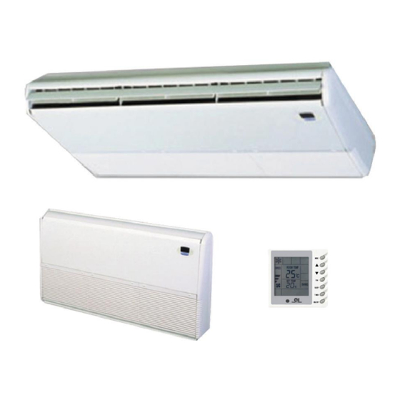
Air Conditioner
FLOOR-TO-CEILING SERIES
MODELS:
indoor unit / outdoor unit
GTH18K3BI / GUHN24NK3AO
GTH24K3BI / GUHN24NK3AO
GTH36K3BI / GUHN36NM3AO
GTH48K3BI / GUHN48NM3AO
Advertisement
Table of Contents

Related Manuals for C&H GTH18K3BI


Summary of Contents for C&H GTH18K3BI
-
Page 1: Air Conditioner
C & H A IR C O N D I T I O N E R S Air Conditioner FLOOR-TO-CEILING SERIES MODELS: indoor unit / outdoor unit GTH18K3BI / GUHN24NK3AO GTH24K3BI / GUHN24NK3AO GTH36K3BI / GUHN36NM3AO GTH48K3BI / GUHN48NM3AO Thanks for your selection of our Air-Conditioning Unit. Before use, please read this instruction... -
Page 2: Safety Considerations
Safety Considerations Please read this manual carefully before use and operate correctly as instructed in the manual. You are specially warned to note the two symbols below.: WARNING! A symbol indicating that improper operation might cause human death or severe injuries. -
Page 3: Wire Controller (Standard Fitting)
Wire controller (standard fitting) SWING SWING TIMER Composition of wire controller Failure st atus display 1 Timing display Sleep st atus display Fan speed display (Auto, High speed, Medium speed, Low speed) Mode key 3 Defros ting st atus display Se t temperatur e incr ease key 4 Ener gy saving st atus display Se t temperatur e decr ease key... - Page 4 Operating instructions of wire controller Turning ON/OFF unit Press the ON/OFF key, then the unit shall start up. Press the ON/OFF key again, then the unit shall shut off. SWING TIMER Fan control (the figures show the relevant display areas) If the fan control key is pressed consecutively, the fan speed shall changes as per...
-
Page 5: Sleep Function Setting
Swing function setting Press Swing button then the swing mode will be operated by the air conditioner. Repress Swing button once to stop swing mode. Note: There is no swing mode for duct type indoor unit SWING SWING TIMER Sleep function setting When under the cooling or dehumidifying mode, after receiving the SLEEP order for 1 hour, the previous set temp. -
Page 6: Operating Mode Setting
Operating Mode Setting This key is pressed consecutively, the operating mode shall change as per the following sequence: Cooling Dehumidifying Heating Auto SWING TIMER When the unit operates under “Cooling” mode, “COOL” shall be displayed. Now the set temperature must be lower than the ambient temperature. Now if the set temperature is higher than the ambient temperature, the unit shall not produce cooling effect but shall only operate under. -
Page 7: Timer Setting
Timer Setting When the unit is shut off, timing start can be set; After the unit is started up, timing shutoff can be set. After the "TIMER" key is pressed, the unit enters the timing set status and the word "TIMER" flashes on the display. Now user can press ( ) or( ) key to increase or decrease the set time. - Page 8 Display outdoor temperature Under normal conditions, the “OUT ENV” column shall only display the indoor temperature. Press the “SLEEP” key for 5 consecutive seconds when the unit is shut off or start up, the LCD shall display “OUT ENV”. After the outdoor temperature is displayed for 10 seconds, the system shall return to the display interface of indoor temperature.
- Page 9 Failure Display When there is failure in the unit operation, “ERROR” will flash on the LCD of the wire controller and the code of failure will also be displayed. When there are multiple failures at the same time, the codes of failures will be displayed one after one on the wire controller.
-
Page 10: Unit Function
Unit Function • 7DP - Seven days programmer (Accessory not supplied) and the week timing functions. Up to timer has the function of invalidating Centralized Control and Week Timer 16 sets of units can be control- led lower unit. The weekly timing function Functions: The centralized control- ler simultaneously by the centralized is able to realized four timing ON/OFF... - Page 11 Note: For upper unit checks 16 lower units consecutively, there will be no more than 16 seconds delay when setting works till unit responds. Please let us know your requirement before your placing the order, for this WEEKLY TIMER will only be prepared when customer orders (communication joint with WEEKLY TIMER on manual control had been prepared).
-
Page 12: Wire Controller (With Week Timer Functions)
Wire controller (with week timer functions) WARNING! ● Never install the wired controller where there is water leakage. ● Never knock, throw or frequently open the wired controller. Fig.1 Each part of wired controller Timing Display Swing Status Display Ambient Temperature Display Timer interval Display Energy Saving Status Display Mode Button... - Page 13 1) ON/OFF(Fig.2) Press the “ON/OFF” button, the unit will start running. Press the “ON/OFF” button again, the unit will stop running. Fig.2 2) Fan Control (Fig.3 is about display region and the same as following figures.) When press FAN button once, the fan speed will be changed as follow: In DRY mode: the fan speed will be set at low automatically.
- Page 14 Setting temperature range under each mode: HEAT -------- 16℃~30℃ COOL -------- 16℃~30℃ DRY -------- 16℃~30℃ FAN -------- can not be set Auto mode is divides into new auto mode and old auto mode. NEW AUTO MODE --------------16℃~30℃ OLD AUTO MODE ---------- can not be set 4) Swing Setting (Fig.5) Press SWING button, SWING will be displayed on the LCD, in which case, the unit is under swing status.
- Page 15 the outdoor unit will be frosted resulting in low efficiency of heating, in which case, the controller will automatically start to defrost with DEFROST displayed. Note: No heating for cooling-only unit and auto mode will be shielded after setting energy saving. Timer Setting (Fig.7, 8, 9) Timer function in this wired controller connected with weekly timer is invalid and wired controller will be...
- Page 16 In timing setting mode, press MODE button to select any desired setting object: Week (1-7), timer interval (1-4), timing (Timer on or Timer off time), min. part or hour part of time, and then press▲ or ▼ button to adjust this object, which is fixed by pressing TIMER button or can be canceled by pressing Timer again.
- Page 17 In deleting timing status, press ▲ or ▼ button to select one day of a week, and then press TIMER ”dd” button confirm, in which case, displayed .The day also can be canceled by pressing TIMER button without “dd” displayed. At last, press ON/OFF button to quit the setting after finish.(Fig.13) 7) Outdoor Ambient Temp Display ( Fig.14) In normal condition, only indoor ambient temp is...
- Page 18 blinking. Press▲ and ▼ to set lower-limit cooling temp (setting range is16-30) and then press ON/OFF to fix .Press ▲ and ▼ to set upper-limit cooling temp, which will be displayed where ambient temp is displayed (setting range is 16-30), and then press ON/OFF to fix. Note: Upper- limit temp can not be set to be lower than lower- limit temp, or else the higher temp will be defaulted to be upper limit and the lower one to be lower- limit.
- Page 19 9) Power–off Memory Setting (Fig.16) Press mode button continuously for 10s and select if memorize startup and stop status of the unit or not at unit.01 displayed in the region of displaying setting temp indicates memorizing start and stop status of the unit after power off .02, quit by pressing ON/OFF button ,indicates not memorizing.
- Page 20 CHECKING BEFORE CONT ACT THE SERVICE MAN CHECKING BEFORE CONTACT THE SERVICE MAN RE CONTACT THE SERVICE MAN OPERATION INSTRUCTIONS OPERATION INSTRUCTIONS PROBLEM PROBLEM CAUSES CAUSES P P R R O O B B L L E E M M C C A A U U S S E E S S Check if breaker switch is still on...
-
Page 21: Indoor Unit Installation
When installing the indoor unit, you can refer the paper pattern for installation, and make sure that the drainage side must be 10mm lower than the other side in order to drain the condensation water fluently. Unit mm Model GTH18K3BI GTH24K3BI 1300 1202... -
Page 22: Selection Of Installation Location
Indoor Unit Installation INSTALLATION INSTRUCTIONS SELECTION OF INSTALLATION LOCATION. CAUTION FOR INSTALLATION WHERE AIR CONDITIONER TROUBLE IS LIKELY Such a place where cool air can be distributed TO OCCUR. through out the room. Where there is too much of oil. Such a place where is condensation water is easily drained Where it is acid base area. - Page 23 Indoor Unit Installation INSTALLATION INSTRUCTIONS Set the suspension bolt.(Use W3/8 or M10 size suspension bolts) Adjust the distance from the unit to the ceiling slab beforehand (Refer to Fig.25) 40mm or less Fig.25 Fig.25 Fig.2 Fig.2 Fig.27 Fig.29 Fig.3...
-
Page 24: Outdoor Unit Installation
Outdoor Unit Installation INSTALLATION INSTRUCTIONS Fig.31 Fig.32 CAUTION... -
Page 25: Electric Wiring Connection
Outdoor Unit Installation INS TALLATION INS T R UC T IONS Electric wiring connection GUHN18NK3AO GUHN48NM3AO GUHN24NK3AO GUHN36NK3AO C A U T I O N Wrong wiring ma y c a us e fire of electric s hock. D o not pull the wire when fixing it with wire clamp and clasp. -
Page 26: Profile Dimensions Of Outdoor Unit
Profile Dimensions of Outdoor Unit Profile Dimensions of Outdoor Unit Fig. 30 U ni t Model GUHN18NK3AO GUHN36NM3AO GUHN24NK3AO GUHN48NM3AO Item 1018 1018 1250 Fig. Unit Installation Instructions Precautions on Installation of Outdoor Unit To ensure the unit in proper function, selection of installation location must be in accordance with following principles: (1) Outdoor unit shall be installed so that the air discharged by outdoor unit will not return and that sufficient space for repair shall be provided around the machine. -
Page 27: Schematic Diagram Of Unit Line Connection
The signal wire between indoor and outdoor unit shall be installed in the shielded bushing, and the unshielded twisted pair cable (UTP) shall be used, the cross sectional area of the cables must be 0.75 GUHN18NK3AO GTH18K3BI GUHN24NK3AO GTH24K3BI Intdoor Unit... - Page 28 Schematic Diagram of Unit Line Connection INSTALLATION INSTRUCTIONS GUHN18NK3AO GUHN24NK3AO GUHN36NM3AO GUHN48NM3AO All the indoor units...
- Page 29 Position and Method of Installing Wire Controller INSTALLATION INSTRUCTIONS Position and Method of Installing Wire Controller INSTALLATION INSTRUCTIONS Position and Method of Installing Wire Controller 1. One end of the control wire of the manual controller is connected with main board of electric box of indoor unit inside, it should be tightened by wire clamp, the other end should be connected with the manual controller (installation sketch map as shown in below).
- Page 30 Position and Method of Installing Wire Controller INSTALLATION INSTRUCTIONS Position and Method of Installing Wire Controller INSTALLATION INSTRUCTIONS Electric box cover Sketch map for indoor unit communication wire Wire clamp Cable-cross loop Control wire Communication wire metallic Pipe metallic Pipe Figure 43 Surface Figure 44 Concealed Figure 45 Schematic Diagram of Installation...
-
Page 31: Position And Method Of Installing Wire Controller
Position and Method of Installing Wire Controller INSTALLATION INSTRUCTIONS Caution: Before installing the electrical equipment, please pay attention to the following matters which have been specially pointed out by our designers: (1) Check to see if the power supply used conforms to the rated power supply specified on the nameplate. -
Page 32: Pipe Preparation
PIPE PREPARATION OPERATION INSTRUCTIONS... -
Page 33: Refrigerant Piping Work
Amount of Additional Max. Pipe Difference between Refrigerant to be Filled Length (m) Indoor Unit and Liquid (For Extra Length of Pipe) Outdoor Unit m Pipe Pipe Model 1/2” GTH18K3BI 1/4" 30g/m GTH24K3BI 5/8” 3/8” 60g/m GTH36K3BI 3/4” 1/2” 120g/m GTH48K3BI... - Page 34 AIR PURGING AND CHECK OF PIPE LEAKAGE OPERATION INSTRUCTIONS...
-
Page 35: Liquid Pipe And Drain Pipe
LIQUID PIPE AND DRAIN PIPE OPERATION INSTRUCTIONS... -
Page 36: Drain Piping Work
DRAIN PIPING WORK OPERATION INSTRUCTIONS45... -
Page 37: Routine Check After Installation
ROUTINE CHECK AFTER INSTALLATION OPERATION INSTRUCTIONS Check after installation Items to be checked Possible malfunction Situation Has it been fixed firmly? The unit may drop, shake or emit noise. It may cause insufficient refrigerating capacity. Have you done the refrigerant leakage test? It may cause condensation and dripping. -
Page 38: Test Running
TEST RUNNING OPERATION INSTRUCTIONS EVALUATION OF THE PERFORMANCE Check electrical main wire's voltage. Use a thermometer to measure cool air both in and out. The difference between in-air and out-air temperature should not be less than Thermometer Check auto-restart function, it can remember the running model before power-broken. Be sure to use the exclusive accessories list above in the installation. - Page 39 This product must not be disposed together with the domestic waste. This product has to be disposed at an authorized place for recycling of electrical and electronic appliances. 66129904712...
Need help?
Do you have a question about the GTH18K3BI and is the answer not in the manual?
Questions and answers