Advertisement
Quick Links
TRANSMITTER BATTERY REPLACEMENT
Replacement battery - 9 volt NEDA 1604 (Eveready 216 or equivalent).
The battery in the transmitter can be checked or changed by removing the front
lower half of the transmitter. Refer to the directions under "accessing the code
switch" for battery replacement.
TO REPLACE OR ADD A SET
A replacem ent or new transm itter or receiver may be purchased by specifying
the Model Number and the RF frequency designated on the identification label.
The RF frequency is set at the factory and must not be adjusted in the field. The
digital code can be m atched to the com panion receiver or transmitter by
following the above procedure.
OPERATIONAL CHECK
To check operation, move back a reasonable distance (about 50 feet) and press
t h e t r a n s m i t t e r b u t t o n . O p e r a tio n s ho uld b e r elia ble at t his di s ta nc e b ut
environm ent and location of both the transmitter and receiver will affect the
range. If the transmitter is stowed well out of sight, it m ay be necessary to
remove it from its mounting and hold near the windshield. Try different locations
and positions. If operation is still unsatisfactory, the problem maybe isolated by:
1 . Checking the door operator. If the door will not open when the wall button is
pressed, the problem is likely to be the operator. If the door will open by
pressing the wall button, but not when the radio control button is pressed,
the problem is probably in the radios.
2.
Replacing the transmitter battery.
If, after performing the above operational checks, the controls still do not
function, they should be returned to your dealer for repair or replacement or they
may be returned, postage prepaid.
CAUTION: A n y c h a n g e s o r m o d i f i c a t i o n s i n i n t e n t i o n a l o r u n i n t e n t i o n a l
radiators which are not expressly approved by LINEAR CORPORATION could
void the user's authority to operate this equipment. This applies to intentional
a n d u n i n t e n t i o n a l r a d ia to r s c er ti fie d pe r p ar t 1 5 of t he F . C . C . r ule s a nd
regulations.
LINEAR CORPORATION
2055 Corte del Nogal • Carlsbad, CA 92008
(760) 438-7000
Copyright © 1999 Linear Corporation
Installation Instructions
GARAGE DOOR RADIO CONTROLS
Your MULTI-CODE™ Radio Controls are designed specifically to remotely
control a garage door from within an automobile and to give years of dependable
service without adjustment. The transmitter/receiver combination utilizes the
MULTI-CODE™ scheme which permits the selection of as many as 1024 code
combinations of the owner's personal choice. Because all radio controls are set
with the even numbered switches in the "ON" position when they leave the
factory, it is recommended that a different code be selected and set at the
time of installation. Please refer to the "Accessing the Code Switch" section for
instructions. The radio frequency (RF) portion of the controls, however, are
tuned to standard frequencies and are thoroughly tested at the factory. This
permits the addition or replacement of either the transmitter or the receiver by
s p e c i f y i n g t h e M o d e l N u m b e r a n d t h e R F f r e q u e n c y d e s i g n a t e d o n t h e
identification label. No RF adjustments are needed nor should any be attempted.
RECEIVER INSTALLATION
The receiver is designed to mount directly to the operator. It can be remotely
installed if the operator terminal strip is not accessible, or if power for the
receiver is not obtainable from the operator. To direct mount the receiver, simply
loosen the terminal screws on the operator and insert the two-way lugs from the
receiver under the screw heads along with the wall button wires), and tighten
the screws (See Fig #1).
Place the antenna (an 11 inch white wire) in a vertical position as far from any
metal as possible.
214961 A
®
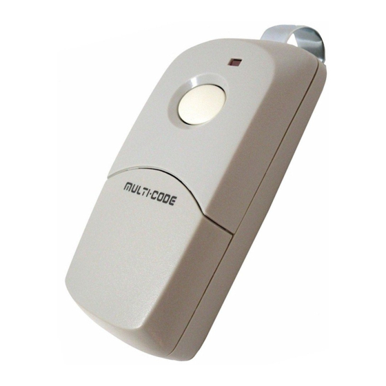
Model 3089 Transmitter
Model 1090 Receiver
WARNING:
• Disconnect power before any installation or repair
• Wear safety glasses
Advertisement

Related Manuals for Multi-code 3089


Summary of Contents for Multi-code 3089
-
Page 1: Installation Instructions
CAUTION: A n y c h a n g e s o r m o d i f i c a t i o n s i n i n t e n t i o n a l o r u n i n t e n t i o n a l tuned to standard frequencies and are thoroughly tested at the factory. This radiators which are not expressly approved by LINEAR CORPORATION could permits the addition or replacement of either the transmitter or the receiver by void the user’s authority to operate this equipment. - Page 2 White wire to terminal “1” or “24v” CODE SWITCH MA TCH Black wire to terminal “2” or “Relay” Red wire to terminal “3” or “Common” (“Radio Power”) OPERA TOR TERMINA L Connect push button wires to terminal “1” and “2” (See Figure #2). Where power for the radio receiver is not available from the operator order a MOUNTING TA B M o d e l 1 0 9 2 - 0 1 p o w e r t r a n s f o r m e r a d a p t o r f o r c o n n e c t i o n b e t w e e n t h e...
Need help?
Do you have a question about the 3089 and is the answer not in the manual?
Questions and answers