Table of Contents
Advertisement
Model Number:
5900859
5900918
5900551
BRIGGS & STRATTON POWER PRODUCTS GROUP, LLC.
5375 NORTH MAIN STREET
MUNNSVILLE, NY 13409
800 933 6175
Operator's Manual
Description
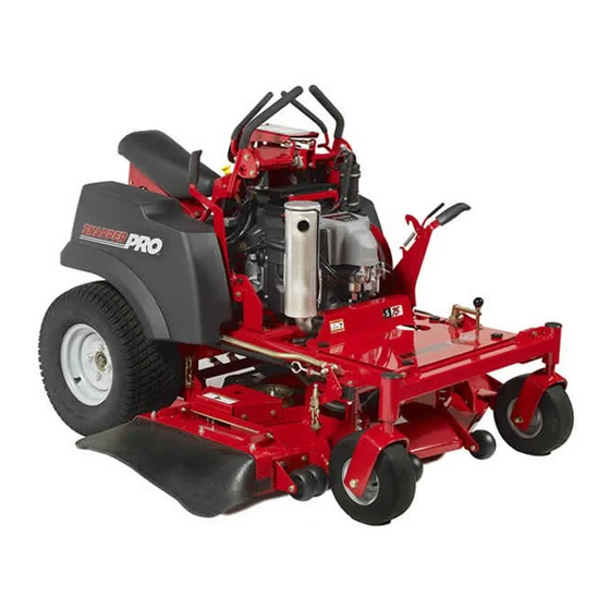
S75XKAV2652, 52" Cut Compact Zero-Turn Riding Mower
S75XKAV2252, 52" Cut Compact Zero-Turn Riding Mower
S75XKAV2352, 52" Cut Compact Zero-Turn Riding Mower
S75X Series
Compact Zero-Turn Riding
Mower
5102230
Rev B
Advertisement
Table of Contents
Troubleshooting

Related Manuals for Snapper 5900859


Summary of Contents for Snapper 5900859
- Page 1 Operator’s Manual S75X Series Compact Zero-Turn Riding Mower Model Number: Description 5900859 S75XKAV2652, 52” Cut Compact Zero-Turn Riding Mower 5900918 S75XKAV2252, 52” Cut Compact Zero-Turn Riding Mower 5900551 S75XKAV2352, 52” Cut Compact Zero-Turn Riding Mower BRIGGS & STRATTON POWER PRODUCTS GROUP, LLC.
- Page 2 Thank you for purchasing this quality-built SNAPPER PRODUCT REFERENCE DATA PRO product. We’re pleased that you’ve placed your confidence in the SNAPPER PRO brand. When Unit Model Number Unit SERIAL Number operated and maintained according to the instructions in this manual, your SNAPPER PRO product will provide many years of dependable service.
-
Page 3: Table Of Contents
Table of Contents Troubleshooting, Adjustments & Service ..44 Operator Safety ..........2 Troubleshooting the Rider ........44 Safety Decals ............8 Troubleshooting the Mower ........45 Safety Interlock System ..........9 Troubleshooting Common Cutting Problems ..46 Safety Icons ............9 Specifications ........... 47 Features & Controls ......... 10 Slope Identification Guide ....... -
Page 4: Operator Safety
Operator Safety Operating Safety Congratulations on purchasing a superior-quality piece of lawn and garden equipment. Our products are designed and manufactured to meet or exceed all industry standards for safety. Do not operate this machine unless you have been trained. Reading and understanding this operator’s manual is a way to train yourself. -
Page 5: Slope Operation
Operator Safety Slope Operation Operation on slopes can be dangerous. Using the unit on a slope that is too steep where you do not have adequate wheel traction (and control) can cause sliding, loss of steering, control, and possible rollover. You should not operate on a slope greater than a 5.4 foot rise over a 20 foot length (15 degrees). - Page 6 Operator Safety Retaining Walls, Drop-offs, and Water Retaining walls and drop-offs around steps and water are a common hazard. Give yourself a minimum of two mower widths of clearance around these hazards and hand-trim with a walk behind mower or string trimmer. Wheels dropping over retaining walls, edges, ditches, embankments, or into water can cause rollovers, which may result in serious injury, death, or drowning.
- Page 7 Operator Safety Read these safety rules and follow them closely. Failure to obey these rules could result in loss of control of unit, severe personal injury or death to you, or bystanders, or damage to property or equipment. This mowing deck is capable of amputating hands and feet and throwing objects. The triangle in text signifies important cautions or warnings which must be followed.
- Page 8 Operator Safety Do Not WARNING 1. Avoid starting, stopping, or turning on a slope. If tires lose traction (i.e. machine stops forward It is a violation of California Public Resource motion on a slope), disengage the blade(s) (PTO) Code, Section 4442, to use or operate the and drive slow off the slope.
- Page 9 Operator Safety SERVICE AND MAINTENANCE 11. Stop and inspect the equipment if you strike an object. Repair, if necessary, before restarting. To avoid personal injury or property damage, use 12. Park machine on level ground. Never allow extreme care in handling gasoline. Gasoline is untrained personnel to service machine.
-
Page 10: Safety Decals
Operator Safety Safety Decals All DANGER, WARNING, CAUTION and instructional messages on your rider and mower This unit has been designed and manufactured to should be carefully read and obeyed. Personal bodily provide you with the safety and reliability you would injury can result when these instructions are not expect from an industry leader in outdoor power followed. -
Page 11: Safety Interlock System
Operator Safety Safety Icons The alert symbol is used to identify safety Safety Interlock System information about hazards that can result in personal injury. A signal word (DANGER, WARNING, or CAUTION) is used with the alert symbol to indicate the likelihood and the potential severity of the injury. This unit is equipped with safety interlock switches. -
Page 12: Features & Controls
Features and Controls Features and Controls Identification Numbers USA Models When contacting your authorized dealer for replacement parts, service, or information you MUST have these numbers. Identification Record your part number, serial number and engine serial numbers in the space provided for easy access. These numbers can be found in the locations shown. -
Page 13: Control Functions
Features & Controls Control Functions The information below briefly describes the function of individual controls. Starting, stopping, driving, and mowing require the combined use of several controls applied in specific sequences. To learn what combination and sequence of controls to use for various tasks see the OPERATION section. Throttle Control Deck Transport Adjustment Handle, Cutting Height Adjustment Handle... - Page 14 Features & Controls Ground Speed Control Levers Ignition Switch These levers control the ground speed of the rider. The ignition switch starts and stops the engine, it has The left lever controls the left rear drive wheel and the three positions: right lever controls the right rear drive wheel.
-
Page 15: Operation
Operation Checks Before Starting Operation • Check that crankcase is filled to full mark on General Operating Safety dipstick (B, Figure 1). See the engine Operator’s Manual for instructions and oil recommendations. Before first time operation: • Make sure all nuts, bolts, screws and pins are in •... -
Page 16: Starting The Engine
Operation Pushing the Rider by Hand WARNING If you do not understand how a specific control DO NOT TOW RIDER functions, or have not yet thoroughly read the Towing the unit will cause hydraulic pump FEATURES & CONTROLS section, do so now. and wheel motor damage. -
Page 17: Zero Turn Driving Practice
Operation Zero Turn Driving Practice Smooth Travel The lever controls of The lever controls of the Zero Turn rider are the Zero Turn rider are responsive, and learning to gain a smooth and responsive. efficient control of the rider’s forward, reverse, and turning movements will take some practice. - Page 18 Operation Practice Turning Around a Corner Practice Turning In Place While traveling forward allow one handle to gradually To turn in place, “Zero Turn,” gradually move one return back toward neutral. Repeat several times. ground speed control lever forward from neutral and one lever back from neutral simultaneously.
-
Page 19: Mowing
Operation Mowing 1. Engage the parking brake. Make sure the PTO switch is disengaged, the ground speed control levers are in the NEUTRAL position and the operator is on the seat. 2. Set the mower cutting height. 3. Start the engine (see STARTING THE ENGINE). 4. -
Page 20: Mowing Methods
Operation When and How Often to Mow The time of day and condition of the grass greatly affect the results you’ll get when mowing. For the best results, follow these guidelines: 1. Mow when the grass is between three and five inches high. - Page 21 Operation Proper Mulching Mulching consists of a mower deck which cuts and recuts clippings into tiny particles and which then blows them down INTO the lawn. These tiny particles decompose rapidly into by-products your lawn can use. UNDER PROPER CONDITIONS, your mulching mower will virtually eliminate noticeable clippings on Figure 11.
-
Page 22: Storage
Operation Storage WARNING Temporary Storage (30 Days Or Less) Fuel and its vapors are extremely flammable and explosive. Remember, the fuel tank will still contain some Fire or explosion can cause severe burns gasoline, so never store the unit indoors or in any or death. -
Page 23: Regular Maintenance
Regular Maintenance Maintenance Maintenance Schedule The following schedule should be followed for normal care of your rider and mower. You will need to keep a record of your operating time. Determining operating time is easily accomplished by observing the elapsed time recorded by the hour meter. -
Page 24: Checking Tire Pressures
Regular Maintenance Check Tire Pressures Tire pressure should be checked periodically, and maintained at the levels shown in the chart. Note that these pressures may differ slightly from the “Max Inflation” stamped on the side-wall of the tires. The pressures shown provide proper traction, improve cut quality, and extend tire life. -
Page 25: Change Oil & Filter
Regular Maintenance Change Oil & Filter 1. Warm engine by running for a few minutes. (Refer to the engine operator’s manual for oil & filter replacement instructions.) 2. Route the oil drain hose (A, Figure 13) over the side of the engine deck and underneath the fuel tank. -
Page 26: Seriving The Hydraulic System
Regular Maintenance Servicing the Hydraulic System Removing the Tank The right hand tank (A, Figure 14) must be removed prior to checking and/or changing the hydraulic oil. 1. Unscrew the three (3) wing bolts (B) that secure the tank to the unit. 2. -
Page 27: Lubrication
Regular Maintenance Lubrication Lubricate the unit at the locations shown in Figures 16 through 20 as well as the following lubrication points. Grease: • front caster wheel axles & yokes • deck lift pivot blocks • mower deck & pump drive idler arm •... -
Page 28: Servicing The Mower Blades
Regular Maintenance Servicing the Mower Blades Removing the Mower Blade CAUTION Avoid injury. Mower blades are sharp. • Always wear gloves when handling mower blades or working near blades. 1. To remove the mower blade, wedge a wooden block between the mower blade and the mower deck housing to keep the blade from turning and remove the mower blade mounting bolt with a 15/16”... - Page 29 Regular Maintenance Sharpening the Mower Blades CAUTION Avoid injury. Mower blades are sharp. • Always wear gloves when handling mower blades or working near blades. • Always wear safety eye protection when grinding 1. Sharpen the mower blade with a grinder, hand file, Figure 24.
-
Page 30: Seat Height Adjustment
Regular Maintenance Seat Adjustment The height of the seat (A, Figure 27) can be adjusted either up or down to accomidate the operator’s comfort level. 1. Remove the seat height adjustment hardware (B, Figure 27). 2. For shorter operators position the seat in the upper mounting hole (C), for taller operators position the seat in the lower mounting hole (D). -
Page 31: Speed Balancing Adjustment
Regular Maintenance Speed Balancing Adjustment If the unit veers to the right or left when the ground speed control levers are in either the maximum forward (both ground speed control levers contacting the handle bars) or reverse position (both ground speed control levers contact the top speed adjustment bolts), the top speed of the ground speed control levers can be adjusted. -
Page 32: Parking Brake Adjustment
Regular Maintenance Parking Brake Adjustment The parking brake system consists of two range selector plates and two parking brake springs which are located by the rear wheels of the unit. If the parking brake needs to be adjusted the range selector plates must be adjusted first, and then the length of the parking brake springs must be set. - Page 33 Regular Maintenance Adjusting the Parking Brake Spring 1. Locate the two (2) brake springs (A, Figure 32). 2. With the parking brake engaged, measure the compressed spring length. The spring should be 2-3/8” (6 cm) when compressed. 3. If the spring length does not equal the measurement, the spring length will need to be adjusted.
-
Page 34: Suspension Adjustment
Regular Maintenance Suspension Adjustment The shock assembly can be adjusted in two ways to allow the operator to customize the ride according 1 2 3 4 5 to the operator’s weight and/or operating conditions. You have the option of adjusting the spring pre-load and/or the upper mounting position. -
Page 35: Mowing Height Adjustment
Regular Maintenance Mowing Height Adjustment See Figure 34. The mowing height can be adjusted by turning the cutting height adjustment handle. To Raise the Mower Deck: Turn the cutting height adjustment handle (A, Figure 34) CLOCKWISE. To Lower the Mower Deck: Turn the cutting height adjustment handle COUNTER- CLOCKWISE. -
Page 36: Deck Lift Rod Timing Adjustment
Regular Maintenance Deck Lift Rod Timing Adjustment 1. Park the machine on a flat, level surface. Disengage the PTO, stop the engine, and engage the parking brake. Rear tires must be inflated to 15 psi (1,03 bar). 2. Measure and record the distance between the lift pivots and the rod pivots. -
Page 37: Deck Leveling Adjustment
Regular Maintenance Deck Leveling Adjustment NOTE: Before adjusting the deck level, the deck lift rod timing must be checked and/or adjusted. 1. Park the machine on a flat, level surface. Disengage the PTO, stop the engine and engage the parking brake. Rear tires must be inflated to 15 psi (1,03 bar). -
Page 38: Pto Drive Belt Replacement
Regular Maintenance PTO Drive Belt Replacement NOTICE To avoid damaging belts, DO NOT pry belts over pulleys. 1. Park the unit on a smooth, level surface such as a concrete floor. Disengage the PTO, engage the parking brake, turn off the engine, and remove the ignition key. -
Page 39: Mower Deck Drive Belt
Regular Maintenance Adjusting the PTO Drive Belt Idler Tensioner Spring Length 1. Loosen the jam nut (B) on the eyebolt (C). 2. Turn the adjustment nut (D) until a measurement of 7-1/4” (18.42 cm) is achieved. 3. Tighten the jam nut. Mower Deck Drive Belt Replacement NOTICE To avoid damaging belts, DO NOT pry belts over... -
Page 40: Hydraulic Pump Drive Belt Replacement
Regular Maintenance 11. Run the mower under no-load condition for about 5 minutes to break-in the new belt. Checking the Deck Drive Belt Idler Tensioner Spring Length 1. Set the mower deck at its middle cutting height. 7-1/4” (18.42 cm) 2. -
Page 41: Fuse Locations
Regular Maintenance 6. Loosen the nut (A, Figure 49) on the spring anchor eyebolt (B) to release the majority of the belt tension. Use caution and remove the nut to completely release the tension. 7” 7. Remove the old belt and replace it with a new (17,8 cm) one. -
Page 42: Battery Maintenance
Regular Maintenance Battery Maintenance NOTE: This unit is equipped with a maintenance-free BCIU1 battery. Removing the Tank The right hand tank (A, Figure 51) must be removed prior to performing maintenance on the battery. 1. Unscrew the three (3) wing bolts (B) that secure the tank to the unit. - Page 43 Regular Maintenance 5. Loosen and remove the hardware that secures the top of the hanger chains (A, Figure 54) to the deck lift rod pivots (B) 6. Loosen and remove the hardware (A, Figure 55) that secures the idler arm mount plate (B) to the mower deck (C).
-
Page 44: Battery Service
Regular Maintenance Battery Service 6. Charge the battery until fully charged (until the specific gravity of the electrolyte is 1.250 or higher and the electrolyte temperature is at least 60° F). WARNING The best method of making certain a battery is Keep open flames and sparks away from the fully charged, but not over charged, is to measure battery;... - Page 45 Regular Maintenance THIS HOOK-UP FOR NEGATIVE GROUND VEHICLES Starter Starter Switch Switch Jumper Cable Starting Discharged Vehicle Vehicle Battery Battery Jumper Cable To Ground Engine Block MAKE CERTAIN VEHICLES DO NOT TOUCH Figure 57. Jump Starting WARNING WARNING Any procedure other than the proceeding could For your personal safety, use extreme caution result in: when jump starting.
-
Page 46: Troubleshooting, Adjustments & Service
Troubleshooting Troubleshooting WARNING Remove the ignition key prior to Troubleshooting Chart performing maintenance on the unit. While normal care and regular maintenance will To avoid serious injury, perform maintenance extend the life of your equipment, prolonged or on the tractor or mower only when the engine constant use may eventually require that service be is stopped and the parking brake is engaged. -
Page 47: Troubleshooting The Mower
Troubleshooting Troubleshooting the Rider continued PROBLEM CAUSE REMEDY Engine runs, but rider will not 1. Hydraulic release valve(s) in “open” 1. Turn hydraulic release valve(s) drive. position. CLOCKWISE to close. 2. Belt is broken. 2. See Drive Belt Replacement. 3. Drive belt slips. 3. -
Page 48: Troubleshooting Common Cutting Problems
Troubleshooting Troubleshooting Common Cutting Problems PROBLEM CAUSE REMEDY Streaking 1. Sharpen your blades. 1. Blades are not sharp. 2. Replace your blades. 2. Blades are worn down too far. 3. Always mow at FULL throttle. 3. Engine speed is too slow. 4. -
Page 49: Specifications
Displacement 44.3 Cu. In (726 cc) Electrical System 12 volt, 15 amp charging coil; Battery: 340 cca Oil Capacity 2.2 US qt (2.1 L) w/ filter For models 5900859 26 Gross HP† Kawasaki Make Kawasaki Model FS730V-AS00-R Displacement 44.3 Cu. in (726 cc) Electrical System 12 volt, 15 amp. -
Page 50: Slope Identification Guide
www.snapperpro.com... - Page 51 Snapper Pro - a division of Briggs & Stratton Power Products Group, LLC. Owner's Limited Warranty Information (Effective 08/01/2007) Thank you for purchasing Snapper Pro commercial mowing equipment. Please take a few minutes to read this limited warranty information. It con- tains all the information you will need to have your Snapper Pro mower repaired in the unlikely event that a breakdown covered by this limited warranty should occur.
- Page 52 Operator’s Manual S75X Series Compact Zero-Turn Riding Mower BRIGGS & STRATTON POWER PRODUCTS GROUP, LLC. 5375 NORTH MAIN STREET MUNNSVILLE, NY 13409 800 933 6175...
Need help?
Do you have a question about the 5900859 and is the answer not in the manual?
Questions and answers