Table of Contents
Advertisement
Quick Links
Advertisement
Table of Contents

Subscribe to Our Youtube Channel
Related Manuals for Tektronix CFG280


Summary of Contents for Tektronix CFG280
- Page 1 User Manual CFG280 11 MHz Function Generator 070-8559-03...
- Page 2 Copyright Tektronix, Inc. 1991. All rights reserved. Tektronix products are covered by U.S. and foreign patents, issued and pending. Information in this publication supercedes that in all previously published material. Specifications and price change privileges reserved. Tektronix, Inc., P.O. Box 1000, Wilsonville, OR 97070–1000...
- Page 3 Tektronix, with shipping charges prepaid. Tektronix shall pay for the return of the product to Customer if the shipment is to a location within the country in which the Tektronix service center is located. Customer shall be responsible for paying all shipping charges, duties, taxes, and any other charges for products returned to any other locations.
-
Page 5: Table Of Contents
....... . . Optional Accessories ....... . . CFG280 User Manual... - Page 6 Table of Contents CFG280 User Manual...
-
Page 7: General Safety Summary
Do Not Operate Without Covers To avoid electric shock or fire hazard, do not operate this product with covers or panels removed. Use Proper Fuse To avoid fire hazard, use only the fuse type and rating specified for this product. CFG280 User Manual... - Page 8 If you suspect there is damage to this product, have it inspected by qualified service personnel. Safety Terms and Symbols Terms in This Manual These terms may appear in this manual: WARNING. Warning statements identify conditions or practices that could result in injury or loss of life. CFG280 User Manual...
-
Page 9: Certifications And Compliances
Manual Certifications and Compliances CSA Certified Power Cords CSA Certification includes the products and power cords appropriate for use in the North America power network. All other power cords supplied are approved for the country of use. CFG280 User Manual... - Page 10 General Safety Summary CFG280 User Manual...
-
Page 11: Getting Started
MHz. The front panel controls also provide selectable gate times (resolution) and selectable X10 attenuation. The CFG280 has a locking, multiposition handle that folds under the instrument. The instrument comes with a power cord, an installed fuse for 115V operation, and this manual. -
Page 12: Preparing The Function Generator For Use
Getting Started Preparing the Function Generator for Use Check the following items prior to operating the CFG280 Function Generator for the first time (see Figure 1 for locations of items 1 through 3): Figure 1: Line Voltage Selectors, Power Input, and Fuse Locations CAUTION. - Page 13 Do not remove the ground lug from the power cord for any reason. 3. Connect the input power cord. Use only the power cords specified for this equipment. Refer to Appendix C: Replaceable Parts on page 29 for power cord part numbers. CFG280 User Manual...
-
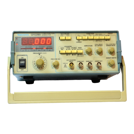
Page 14: Front Panel
Getting Started Front Panel Figure 2 shows the front-panel controls, connectors, and indicators of the CFG280 Function Generator. 10 11 Figure 2: Front Panel Controls, Connectors, and Indicators 1. OVERRANGE LED. Lights if you apply a frequency above specified limits to the EXT COUNTER INPUT connector. It also lights if the gate time is too slow for the incoming signal. - Page 15 (see Table 1 on page 6). When you push either button in, the output frequency is 1/10 of the value shown on the FREQUENCY dial. When you push both buttons in, the output frequency is 1/19 of the value shown on the FREQUENCY dial. CFG280 User Manual...
- Page 16 This button enables the SWEEP RATE and SWEEP WIDTH knobs. You can also feed an external sweep signal into the CFG280 Function Generator through a connector on the rear panel. See External Sweep on page 11 for further details.
- Page 17 EXT COUNTER INPUT. When you push the button out the counter readout displays the frequency count of the signal being generated by the CFG280 Function Generator. 15. MAIN Button. Selects between two voltage ranges: 0 V...
-
Page 18: Rear Panel
See page 13 for details. 2. EXT AM INPUT BNC. This connector accepts external amplitude modulation signals. See page 12 for details. 3. VCF INPUT BNC. This connector accepts external sweep signals. See page 11 for details. CFG280 User Manual... -
Page 19: Reference
TTL Signals To generate a TTL signal, follow these steps: 1. Connect the SYNC OUT connector on the CFG280 Function Generator to the input BNC connector on an oscilloscope (see Figure 4) . Test oscilloscope... -
Page 20: Internal Sweep
Internal Sweep To use the internal sweep function, follow these steps: 1. Connect the MAIN OUT BNC on the CFG280 Function Generator to the device under test, such as a filter (see Figure 5). 2. Connect the SWEEP OUT connector to one channel of an oscilloscope (see Figure 5). -
Page 21: External Sweep
Use the SWEEP RATE knob to adjust the sweep rate. External Sweep To use the external sweep function, follow these steps: 1. Connect the MAIN OUT connector on the CFG280 Function Generator to the oscilloscope input connector (see Figure 6). To VCF INPUT... -
Page 22: Amplitude Modulation
Reference 2. Turn the Frequency Dial to the 0.1 position. CAUTION. To avoid damage to the CFG280, ensure that the maximum voltage into the rear panel VCF INPUT is no more than 10 V pk. 3. Connect an external voltage signal to the VCF INPUT on the rear panel of the instrument (see Figure 6). -
Page 23: Tone-Burst Generation And Stepped Frequency Multiplication
This application requires another function generator (such as the Tektronix CFG253) to serve as a gating signal source and a ramp generator to serve as a VCF signal source. 1. Connect the MAIN OUT connector on the CFG280 Function Generator to the oscilloscope input connector (see Figure 8). - Page 24 3. Connect the MAIN OUTPUT of the CFG253 to a BNC T connector. Connect the BNC T outputs to the GATE INPUT connector on the CFG280 Function Generator and the external input on the ramp generator (see Figure 8). 4. Set the ramp generator to generate the desired ramp duration and polarity.
- Page 25 7. Select the sweep frequency range by adjusting the FREQUENCY dial to one end of the swept range (upper or lower limit, depending on the polarity of the ramp) and adjusting the other end with the RG501 output amplitude. CFG280 User Manual...
- Page 26 Reference CFG280 User Manual...
-
Page 27: Appendix A: Specifications
Appendix A: Specifications Tables 2 through 5 show characteristics of the CFG280 Function Generator that are guaranteed by warranty. Table 2: Generator Specifications Characteristic Measurement Outputs Square wave, sine wave, triangle wave, TTL pulse, positive and negative ramp, pulse and... - Page 28 Internal Sweep Width Variable from 1:1 to 100:1 Amplitude Modulation 100% with , DC to 200 kHz DSB suppressed carrier modulation is also obtained by input modulating the signal with +2.5 VDC offset Input impedance = 3 k CFG280 User Manual...
- Page 29 42 V peak Internal Time Base Crystal Frequency 10 MHz Temperature Stability <0.001% (10 ppm from 0 C to 40 C) Line Voltage Stability < 1 ppm with 10% line voltage variation Aging Rate < 10 ppm/yr CFG280 User Manual...
- Page 30 EC Declaration of Compliance was demonstrated to the following specification as Conformity – Low listed in the Official Journal of the European Communities: Voltage Low Voltage Directive 73/23/EEC, amended by 93/68/EEC. HD401 S1 Safety Requirements for Electronic Measuring Aparatus. CFG280 User Manual...
- Page 31 Appendix A: Specifications Table 6: Typical Mechanical Specifications Characteristic Measurement Dimensions 100 mm X 240 mm X 230 mm (H x W x D) (3.9 in x 9.5 in x 9.0 in) Weight 3.0 kg (6.6 lb) CFG280 User Manual...
- Page 32 Appendix A: Specifications CFG280 User Manual...
-
Page 33: Appendix B: Maintenance
This appendix provides information for the basic maintenance of the CFG280 Function Generator. Cleaning To clean the CFG280 Function Generator, use a soft cloth dampened in a solution of mild detergent and water. Do not spray cleaner directly onto the instrument, since it may leak into the cabinet and cause damage. -
Page 34: Troubleshooting
The diagrams do not provide instructions for or recommend instrument disassembly. If these diagrams fail to solve your problem, send your instrument to the nearest Tektronix service center. NOTE. These diagrams assume that any other test equipment you use is operating properly. - Page 35 Send your instrument to the nearest Tektronix service center. you using the Toggle the external input SOURCE button. connector? Check connection and voltage level of signal. CFG280 User Manual...
- Page 36 Adjust with amplitude settings too AMPLITUDE low to produce visible knob and MAIN signal? button. Push appropriate MULTIPLIER and range and function FUNCTION selected? buttons. Send your instrument to the nearest Tektronix service center. CFG280 User Manual...
- Page 37 Tektronix service center. Is signal Pull DC OFFSET knob responsive to DC DC OFFSET knob out to activate DC offset offset pulled out? function. adjustments? Send your instrument to the Done. nearest Tektronix service center. CFG280 User Manual...
- Page 38 Appendix B: Maintenance CFG280 User Manual...
-
Page 39: Appendix C: Replaceable Parts
Appendix C: Replaceable Parts Replaceable parts may be ordered directly from your authorized Tektronix dealer. Standard Accessories The following items are shipped with the CFG280 Function Generator: Table 7: Standard Accessories Accessory Tektronix Part Number Fuse, 3AG, 0.6 A, 250 V, SB 159–0043–00... - Page 40 Table 9: Accessory Power Cords Tektronix Part Plug Configuration Normal Usage Number North America 161-0104-00 115 V Europe 161-0104-06 230 V United Kingdom 161-0104-07 230 V Australia 161-0104-05 230 V North America 161-0104-08 230 V Switzerland 161-0167-00 230 V CFG280 User Manual...
Need help?
Do you have a question about the CFG280 and is the answer not in the manual?
Questions and answers