Bosch 670 Series Installation And Operation Manual
Hide thumbs
Also See for 670 Series:
- Quick install manual (21 pages) ,
- Manual (5 pages) ,
- Specifications (4 pages)
Table of Contents
Advertisement
Quick Links
Advertisement
Table of Contents

Related Manuals for Bosch 670 Series


Summary of Contents for Bosch 670 Series
- Page 1 Video Recorder 670 Series DVR 670 Series Installation and Operation manual...
-
Page 3: Table Of Contents
Video Recorder 670 Series Table of Contents | en Table of Contents Safety Safety precautions Important safety instructions Important Notices Bosch notices Introduction Digital video recorder applications 2.1.1 Versions 2.1.2 Manuals 2.1.3 Features Unpacking 2.2.1 Package contents Installation environment 2.3.1 Mounting 2.3.2... - Page 4 | Table of Contents Video Recorder 670 Series USB connectors eSata connector 4.10 External alarm I/O connection 4.11 Power supply 4.12 Maintenance Operating instructions Front panel controls 5.1.1 Keys 5.1.2 Indicators Mouse Controls Remote control Viewing pictures 5.4.1 Monitor A 5.4.2...
- Page 5 Video Recorder 670 Series Table of Contents | en 6.3.1 Language 6.3.2 Monitor A 6.3.3 Monitor B Event 6.4.1 Input 6.4.2 Motion 6.4.3 Alarm acknowledge 6.4.4 System menu Network 6.5.1 TCP/IP 6.5.2 Streaming to mobile devices 6.5.3 Connecting using a smart mobile phone 6.5.4...
- Page 6 | Table of Contents Video Recorder 670 Series Find image Video slider bar Checking authenticity Exit button Menu default values Technical specifications 10.1 Electrical 10.1.1 Mechanical 10.1.2 Environmental 10.1.3 Electromagnetic and Safety 10.2 DVD compatibility 10.3 USB memory sticks...
-
Page 7: Safety
Video Recorder 670 Series Safety | en Safety Safety precautions DANGER! High risk: This symbol indicates an imminently hazardous situation such as "Dangerous Voltage" inside the product. If not avoided, this will result in an electrical shock, serious bodily injury, or death. - Page 8 17. Attachments, changes or modifications - Only use attachments/accessories specified by the manufacturer. Any change or modification of the equipment, not expressly approved by Bosch, could void the warranty or, in the case of an authorization agreement, authority to operate the equipment.
-
Page 9: Important Notices
Disposal - Your Bosch product was developed and manufactured with high-quality material and components that can be recycled and reused. This symbol means that electronic and electrical appliances, which have reached the end of their working life, must be collected and disposed of separately from household waste material. - Page 10 SELV - All the input/output ports are Safety Extra Low Voltage (SELV) circuits. SELV circuits should only be connected to other SELV circuits. Video loss - Video loss is inherent to digital video recording; therefore, Bosch Security Systems cannot be held liable for any damage that results from missing video information. To minimize the risk of lost digital information, Bosch Security Systems recommends multiple, redundant recording systems, and a procedure to back up all analog and digital information.
-
Page 11: Fcc
Video Recorder 670 Series Safety | en FCC Information (U.S.A. and Canadian Models Only) This equipment has been tested and found to comply with the limits for a Class B digital device, pursuant to part 15 of the FCC Rules. These limits are designed to provide reasonable protection against harmful interference in a residential installation. -
Page 12: Bosch Notices
| Safety Video Recorder 670 Series Bosch notices Copyright This manual is the intellectual property of Bosch Security Systems and is protected by copyright. All rights reserved. Trademarks All hardware and software product names used in this document are likely to be registered trademarks and must be treated accordingly. -
Page 13: Introduction
A dedicated PC player is provided for playback of secure video files. 2.1.1 Versions There are various DVR 670 Series models; the most extensive model has 16 channels and a built-in DVD writer. 2.1.2 Manuals This manual contains information about: –... -
Page 14: Features
If any items are missing, notify your customer service representative or Bosch Security Systems sales representative. The shipping carton is the safest container in which to transport the unit. Save it and all packing materials for future use. -
Page 15: Installation Environment
Introduction | en Installation environment 2.3.1 Mounting The DVR 670 Series is supplied as a desktop unit. 2.3.2 Ventilation Ensure that the location planned for the installation of the unit is well ventilated. Take note of the locations of the cooling vent in the unit's enclosure and ensure that they are not obstructed as this might cause the unit to fail and void the warranty. -
Page 16: Quick Install
Connect up to 4 ALARM OUT outputs (via the supplied terminal blocks). Connect a pan/tilt/zoom control unit to the RS-485 or RS-232 port. Connect to your network via the Ethernet port. Connect a Bosch Intuikey keyboard cable to the Keyboard-IN port if required. 3.1.3 Powering up Switch on all connected equipment. -
Page 17: First-Time Use
Video Recorder 670 Series Quick install | en First-time use The Quick install menu opens the first time the unit is used. Fill in the basic settings in the three tabs to get the unit operational. The unit begins recording automatically when the Quick install menu is closed. -
Page 18: Quick Install Menu
| Quick install Video Recorder 670 Series Quick install menu The Quick install menu contains three tabs: International, Continuous Recording, and Network. Click the Exit button to exit the Quick install menu. Changing Quick install settings overwrites customized settings. -
Page 19: Continuous Recording
Video Recorder 670 Series Quick install | en 3.3.2 Continuous Recording Figure 3.4 Quick install - Continuous Recording Set the Continuous Recording Resolution, Quality, Frame rate, Covert, and Audio for each profile in the table. Bosch Security Systems Installation and Operation manual... -
Page 20: Network
| Quick install Video Recorder 670 Series 3.3.3 Network Figure 3.5 Quick install - Network Fill in the settings that control the behavior of the unit with respect to a network. DVR ID Enter a unique DVR name to be used in the network. -
Page 21: Hardware Setup
Video Recorder 670 Series Hardware setup | en Hardware setup This chapter contains detailed information about the hardware installation and connection of external equipment to the unit. The connector types and their pin signals are described. Most of the connectors are located at the rear panel of the unit. For convenience, one USB port is located on the front of the unit to connect a mouse or memory device. -
Page 22: Audio Connections
| Hardware setup Video Recorder 670 Series Audio connections The DVR 600 Series supports up to 4 audio inputs and 2 audio outputs. Connect using audio cable with RCA (CINCH) compatible connectors. Specifications Input signal: Mono RCA (CINCH), 1 Vpp, 10k ohm... -
Page 23: Keyboard Connections
Hardware setup | en Keyboard connections The keyboard input and output connectors are used to connect a Bosch Intuikey keyboard to one or more DVR 600 Series units. For one unit, connect the keyboard to the Keyboard in connector. For more units, connect a cable between the Keyboard out connector of the first unit and the Keyboard in connector of the following DVR 600 Series unit. -
Page 24: Ethernet Connection
| Hardware setup Video Recorder 670 Series Ethernet connection The standard RJ-45 Ethernet socket is used to connect the unit directly to a PC or to a network. To connect directly to a network hub or switch, use a straight-through network cable. -
Page 25: Rs485 Port
Video Recorder 670 Series Hardware setup | en RS485 port Connect Bosch, Pelco-P or Pelco-D controllable cameras to the unit for pan, tilt, and zoom control. The Bosch protocol is supported with the following baud settings: – 9600 baud –... -
Page 26: Usb Connectors
An eSata connector is located at the rear panel of the unit to connect an eSata device. This can be used to expand the number of available hard disks. e-SATA Figure 4.10 eSata connector Note: The connected hard disks must be Bosch approved. AM18-Q0617 | v2.0 | 2012.03 Installation and Operation manual Bosch Security Systems... -
Page 27: External Alarm I/O Connection
Video Recorder 670 Series Hardware setup | en 4.10 External alarm I/O connection Alarm inputs and outputs are supplied screw down terminal blocks. The screw terminal blocks are supplied with the unit. Connecting the inputs Each (alarm) input line can be switched by a contact from an external device between an numbered input and ground (G). -
Page 28: Power Supply
| Hardware setup Video Recorder 670 Series 4.11 Power supply DC power is supplied to the DVR 600 from an AC/DC power supply unit delivered with the unit. For operational reasons, the DVR 600 has no on/off switch . This means that the unit is always powered as long as the power cable from the power supply unit is connected to the 12VDC socket. -
Page 29: Operating Instructions
Video Recorder 670 Series Operating instructions | en Operating instructions These instructions explain the purpose of the front panel keys. The functions available can be limited by setting passwords. Access to the units functions are determined by the user level of the user logged in. -
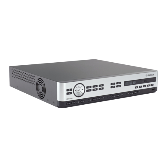
Page 30: Front Panel Controls
| Operating instructions Video Recorder 670 Series Front panel controls Figure 5.1 Front panel controls Note: 8-channel models have only 8 camera keys on the front. 5.1.1 Keys The keys on the front panel control all functions. Symbols on the keys show the functions. -
Page 31: Indicators
Video Recorder 670 Series Operating instructions | en Acknowledge key – press to acknowledge an alarm event; a red indicator light is located on the key Camera keys (1-8/16) – press to see a full-screen display of the video input –... -
Page 32: Mouse Controls
| Operating instructions Video Recorder 670 Series Mouse Controls All functions controlled by the front panel can, alternatively, be accessed using the supplied USB mouse. All main DVR functions are accessible via the System Control Bar. To display the... -
Page 33: Remote Control
Video Recorder 670 Series Operating instructions | en Remote control All functions controlled by the front panel and USB mouse can, alternatively, be accessed using the supplied remote control. The IR remote control allows control of up to nine units without interfering with one another. -
Page 34: Viewing Pictures
| Operating instructions Video Recorder 670 Series Viewing pictures The unit has two monitor outputs, A and B. The way in which these monitors display pictures depends on how the system is configured. 5.4.1 Monitor A Monitor A is the main monitor. It shows full-screen, quad or multiscreen live or playback camera pictures. -
Page 35: Viewing
Video Recorder 670 Series Operating instructions | en 5.4.3 Viewing The tables show all possible views for monitor A. The set of muti-screen views available depends on the resolution (aspect ratio) setting and the model type (8 or 16 channels). - Page 36 | Operating instructions Video Recorder 670 Series Quad screen To view quad displays: – Press the quad key. – A quad display of camera pictures appears on the active monitor. Full-screen To view a full-screen shot of a camera: –...
- Page 37 Video Recorder 670 Series Operating instructions | en Freeze image Freezing a camera shot on monitor A: Press the pause key to freeze all the picture in the active cameo. Press the stop key to return to live viewing. Alternatively, right click in the active cameo and select Freeze or Unfreeze from the context menu using the mouse.
-
Page 38: Live And Playback
| Operating instructions Video Recorder 670 Series Live and playback 5.5.1 Live mode The live mode is the normal operating mode of the unit where live pictures are viewed from the cameras. From live mode, switch to playback mode or the system menu. -
Page 39: Overview Of The Menu System
Video Recorder 670 Series Operating instructions | en Overview of the menu system The Main menu gives access to several functions to help use the unit. Access to the Main menu is only possible with a User Account at the Administrator User Level. There are three ways of accessing the Main menu: –... -
Page 40: Main Menu
| Operating instructions Video Recorder 670 Series 5.6.3 Main menu Camera The Camera menu is used to configure recording settings for the unit. The menu contains eight submenus: – Camera - per camera Enable, Name of the camera, Covert, and Audio –... -
Page 41: Search
Video Recorder 670 Series Operating instructions | en – Configuration - Import and Export configuration, reset to Factory defaults, Update firmware and Quick install – Hard Disk - set Overwrite, Disk full warning, Event partition, Auto delete, and format the disk –... -
Page 42: Date/Time Search
| Operating instructions Video Recorder 670 Series 5.7.1 Date/time search Select the start date. Once the start date has been selected, the timeline will update to show the full 24 hour period. Use the Zoom In button to magnify the timeline. -
Page 43: Event Search
Video Recorder 670 Series Operating instructions | en 5.7.2 Event search From a Date/Time search, press the exit key to select the Search Tabs. Press the left/right arrow keys to select Event Search. Press the enter key to activate the search. -
Page 44: Smart Search
| Operating instructions Video Recorder 670 Series 5.7.3 Smart search From a Date/Time search, press the exit key to select the Search Tabs. Press the left/right arrow keys to select Smart Search. Press the enter key to activate the search. -
Page 45: Export
Video Recorder 670 Series Operating instructions | en Export The export menu is accessed by pressing the Export key on the Front Panel or from the System Control Bar. It allows writing segments of recorded video and audio to a USB storage device or recordable DVD. -
Page 46: System Information
| Operating instructions Video Recorder 670 Series System information The System information screen is accessed from the System Control Bar by pressing the System Information icon. The System information menu contains: – Model Name – Serial Number – Video Format –... - Page 47 Video Recorder 670 Series Operating instructions | en Figure 5.11 System Control Bar - Video signals information The video information menu shows the video system that has been set and the inputs on which video signals have been detected. Click Hard disk to see more information about the hard disks.
- Page 48 The Disk info menu provides information on the size and usage data of the hard drives. Note: Only Bosch hard disks with a signature can be used. If the hard disk is not certified, it cannot be used for recording.
-
Page 49: Log
Video Recorder 670 Series Operating instructions | en 5.10 The Log displays historic system events and is accessed from the System Control Bar by pressing the Log icon. Logbook filter From the Log display, make a selection of which system events to show. -
Page 50: Triggers And Alarms
| Operating instructions Video Recorder 670 Series 5.11 Triggers and alarms Various types of events change the way the unit works. These events are: – an alarm input signal applied to the unit – motion detection in a camera signal –... -
Page 51: Motion Events
Video Recorder 670 Series Operating instructions | en Acknowledging an input alarm Press the acknowledge key to acknowledge the alarm. – The beeper is silent. – The alarm indicators are no longer lit. – The alarm status message disappears. –... -
Page 52: Configuration Menu
| Configuration menu Video Recorder 670 Series Configuration menu Access all the parameters that are used to configure the unit via the menu system. The large number of available parameters gives the opportunity to program extensive functionality. Administrator rights are required to access the configuration menus. - Page 53 Video Recorder 670 Series Configuration menu | en Top tabs Icon Submenus Camera Camera Video Adjustment Continuous Recording Input Recording Motion Recording Network Live Streaming Video Format Schedule Sunday Monday Tuesday Wednesday Thursday Friday Saturday Exception Days Display Language Monitor A...
-
Page 54: Camera
| Configuration menu Video Recorder 670 Series Camera Use the Camera menu to configure the recording set up for each of the three profiles. Configure the settings for Continuous, Input, and Motion recording. – Continuous recording - the default recording mode –... -
Page 55: Video Adjustment
Video Recorder 670 Series Configuration menu | en 6.1.2 Video adjustment Figure 6.3 Camera - Video adjustment Channel Select the camera channel for adjustment. The preview will display the channel indicated. Bosch Security Systems Installation and Operation manual AM18-Q0617 | v2.0 | 2012.03... -
Page 56: Ptz
| Configuration menu Video Recorder 670 Series 6.1.3 Figure 6.4 Camera - PTZ Select a COM port, Control ID, and Protocol for PTZ when a controllable camera is connected. – Pan and Tilt can be tested within the menu. -
Page 57: Continuous Recording
Video Recorder 670 Series Configuration menu | en 6.1.4 Continuous Recording Figure 6.5 Camera - Continuous Recording Continuous recording mode: – Resolution - set the video resolution to 4CIF (704x576/480 PAL/NTSC), 2CIF (704x288/ 240 PAL/NTSC), or CIF (352x288/240 PAL/NTSC). –... -
Page 58: Input Recording
| Configuration menu Video Recorder 670 Series 6.1.5 Input Recording Figure 6.6 Camera - Input Recording Use the same procedure as in Continuous Recording. Pre-event Pre-event recording can be switched off or to a displayed pre-event recording time by input and motion recording. -
Page 59: Motion Recording
Video Recorder 670 Series Configuration menu | en 6.1.6 Motion Recording Figure 6.7 Camera - Motion Recording Use the same procedure as in Input Recording. 6.1.7 Network Live Streaming Figure 6.8 Camera - Network Live Streaming Use the same procedure as Continuous Recording to set the values for cameras that will be streamed over the network. -
Page 60: Video Format
| Configuration menu Video Recorder 670 Series – Network streaming performance is limited by the total bandwidth between the unit and the PC running the Web-based control application. – Network stream resolution setting is CIF only and the frame rate is equal or less than the recording streams. -
Page 61: Schedule
Video Recorder 670 Series Configuration menu | en Schedule Setting the dynamic characteristics The settings in the Schedule menu provide the opportunity to tap the powerful functionality of the unit. By spending some time in planning and setting up the schedules, efficient use of resources is achieved while effectively covering most types of working situations. -
Page 62: Display
| Configuration menu Video Recorder 670 Series Exception days – Up to 32 exceptions can be set that override the schedule. – To add an exception, select Add. Choose the date from the Calendar. – To edit an exception, select List and then select the value to edit. -
Page 63: Event
Video Recorder 670 Series Configuration menu | en Event Use the Event menu to specify the desired behavior for an Input, detected Motion, or System failures; also define how alarms are acknowledged. 6.4.1 Input Figure 6.12 Event - Input Inputs are always active on the unit. -
Page 64: Motion
| Configuration menu Video Recorder 670 Series 6.4.2 Motion The motion detection feature can be configured by selecting the camera channel for each individual video input. Figure 6.13 Event - Motion Adjust the Sensitivity to set the threshold at which Motion is detected. -
Page 65: Alarm Acknowledge
Video Recorder 670 Series Configuration menu | en 6.4.3 Alarm acknowledge The alarm acknowledge feature can be configured for automatic or manual operation. Figure 6.14 Event - Alarm acknowledge Select the Post-event time to enable the unit to automatically acknowledge alarms when the post-event time is expired. -
Page 66: System Menu
| Configuration menu Video Recorder 670 Series 6.4.4 System menu The relay outputs can be configured to react to system events. Figure 6.15 Event - System menu For each system event, select relay number 1, 2, 3 or 4 to activate an output relay when an events occurs, or select None for no activation. -
Page 67: Network
Video Recorder 670 Series Configuration menu | en Network 6.5.1 TCP/IP Figure 6.16 Network - TCP/IP Enable DHCP to have the IP address, subnet mask, and default gateway assigned automatically by the network server. – If DHCP is disabled, fill in the IP address, the Subnet mask, the default Gateway, and the Primary DNS server address. - Page 68 | Configuration menu Video Recorder 670 Series stream or the local recording stream if the remote stream is disabled.Performance depends on the decoding performance of mobile device. Streaming may fail if the bandwidth of the internet connection is too low.You can connect to the DVR 600 to view one live-view channel as follows: Enable RTSP On in Network-TCP/IP menu for DVR 600.
-
Page 69: Ddns
Video Recorder 670 Series Configuration menu | en 6.5.4 DDNS Figure 6.17 Network - DDNS Select a DDNS provider from the list and complete the details with the configuration information assigned by the provider. The providers supported are: dyndns.org, tzo.com, and sitessolutions.com. -
Page 70: Mail
| Configuration menu Video Recorder 670 Series 6.5.6 Mail Figure 6.19 Network - Mail Enable Send Mail to have an e-mail sent out from the system according to the settings in the Notification Menu. Use More E-mail Settings to set the From, Subject, and up to three recipients. -
Page 71: System
Video Recorder 670 Series Configuration menu | en More E-mail Settings - From This is the e-mail address that will appear as the sender of all e-mail originating from the unit. More E-mail Settings - Subject This is the subject that will appear in all e-mail sent by the unit. -
Page 72: Beeper
| Configuration menu Video Recorder 670 Series 6.6.3 Beeper Select when the unit will Beep: – On every Button press – When the unit is triggered by an Input, Motion, System failure, or Video loss. 6.6.4 Users Figure 6.21 System -User General The system contains a permanent Admin account with Administrator permissions. -
Page 73: Configuration
Video Recorder 670 Series Configuration menu | en Figure 6.22 System - Change user rights for normal user 6.6.5 Configuration Figure 6.23 System - Configuration – Import configuration will load previously saved system settings from a USB memory device. –... -
Page 74: Hard Disk
| Configuration menu Video Recorder 670 Series 6.6.6 Hard Disk Figure 6.24 System - Hard disk The Hard Disk menu gives access to settings that affect video retention as well as a means to format the hard disk. –... -
Page 75: System
Video Recorder 670 Series Configuration menu | en 6.6.7 System Figure 6.25 System - System The System menu contains miscellaneous settings for the unit. – IR remote control allows for up to nine units to receive commands from a single remote control without interfering with one another. -
Page 76: Web Client Software
| Web Client Software Video Recorder 670 Series Web Client Software The Web Client Software gives full remote control of the DVR 600 Series using a PC. Up to four remote users can access and control the unit. Remote live viewing, search, playback, and system configuration are provided. -
Page 77: How To Log On
Video Recorder 670 Series Web Client Software | en How to log on When establishing a new connection to the unit, the Log on window appears. Figure 7.1 Web Client - Log on window via a network Type the User ID and Password. -
Page 78: Introducing The Browser Window
| Web Client Software Video Recorder 670 Series Introducing the browser window The browser window is built up of three main areas: – A mode bar across the top, containing buttons for changing between live and playback, export, system settings, and buttons to toggle video between full screen, quad, multi- screen or sequence. -
Page 79: Camera Views
Video Recorder 670 Series Web Client Software | en 7.3.2 Camera views To switch the display mode, click one of the camera view buttons to change the cameo display configuration: – Single view, Quad view, Multi-screen and Sequence display modes are available. -
Page 80: Export Mode
| Web Client Software Video Recorder 670 Series 7.3.4 Export mode Click the Export button to show the export window. On this screen, the user can: – export a file remotely to the PC; – choose the channel, audio, start and end date/times to export. -
Page 81: Configuration Mode
Video Recorder 670 Series Web Client Software | en 7.3.5 Configuration mode Click the Configuration button to enter the Configuration menu. This allows set up of all the configuration settings for the unit. Figure 7.5 Web Client - Configuration Bosch Security Systems Installation and Operation manual AM18-Q0617 | v2.0 | 2012.03... -
Page 82: Archive Player
| Archive Player Video Recorder 670 Series Archive Player Getting started The DVR 600 Series Divar Archive Player allows viewing archived video recordings on a PC that have been archived from the DVR or Web Client. It also provides the opportunity to check the authenticity of the archived video. -
Page 83: Introducing The Main Window
Video Recorder 670 Series Archive Player | en Introducing the main window The main window appears upon selection of an archive file. The window is built up of three main areas: – A horizontal top bar containing buttons for screen control. -
Page 84: Viewing Images
| Archive Player Video Recorder 670 Series Viewing Images 8.4.1 Assigning Cameos A cameo is a single camera picture in a multiscreen display. To assign a camera to a cameo: Click on a Cameo; – the selected cameo has a yellow border. -
Page 85: Capturing A Still Image
Video Recorder 670 Series Archive Player | en 8.5.1 Capturing a still image Capture still images from the full screen display of a camera and save them to the PC hard disk in a bitmap format. To save an image from the active cameo to the PC hard disk: Click the Capture button;... -
Page 86: Menu Default Values
| Menu default values Video Recorder 670 Series Menu default values The following tables list the items of the menu system of the unit. The Default value column shows the values that are restored when the factory defaults item of the System settings menu is selected. - Page 87 Video Recorder 670 Series Menu default values | en Table 9.2 Configuration menu default values Navigation Setting Default value Reset Camera Camera Cameras 1 ~ 8/16 Enable Name Camera 01~08/16 Covert Audio None Video Adjustment Cameras 1 ~ 8/16 Brightness...
- Page 88 | Menu default values Video Recorder 670 Series Table 9.2 Configuration menu default values Navigation Setting Default value Reset Display Language Language English Monitor A Camera Name Camera Status Date/Time Playback Date/Time Playback Status HDD Status Event Popup Sequence Dwell Time...
- Page 89 Video Recorder 670 Series Menu default values | en Table 9.2 Configuration menu default values Navigation Setting Default value Reset Network TCP/IP DHCP Enabled IP Address 0.0.0.0 Subnet Mask 0.0.0.0 Gateway 0.0.0.0 Primary DNS 0.0.0.0 Secondary DNS 0.0.0.0 HTTP Port No.
- Page 90 | Menu default values Video Recorder 670 Series Table 9.2 Configuration menu default values Navigation Setting Default value Reset System Date/Time Date 2010-01-01 Time 12:00:00 AM Date Format YYYY/MM/DD Time Format 12 hour Time Zone GMT+0 Daylight Savings Daylight Savings...
-
Page 91: Technical Specifications
±25 V RS485 Output signals according to RS485 max. signal voltage -8 V to +12 V RS485 support Bosch domes and Pelco-P and D Keyboard Intuikey; 12 VDC, 400 mA max. Bosch Security Systems Installation and Operation manual... -
Page 92: Mechanical
| Technical specifications Video Recorder 670 Series Connectors Video inputs 8/16 looping BNC, auto-terminating Audio inputs 4 RCA (CINCH) Ethernet RJ45, 10/100/1000BaseT according to IEEE802.3 Monitors VGA D-sub, HDMI, BNC Audio outputs 2 RCA Alarm connectors Screw terminal inputs, cable cross section AWG 26-16 (0.13-1.5 mm2) -
Page 93: Environmental
Video Recorder 670 Series Technical specifications | en 10.1.2 Environmental Temperature Operating: 0 °C to +40 °C (+32 °F to +104 °F) Storage: -40 °C to +70 °C (-40° F to +158 °F) Relative humidity Operating: <93% non-condensing Storage: <95% non-condensing... -
Page 94: Electromagnetic And Safety
| Technical specifications Video Recorder 670 Series 10.1.3 Electromagnetic and Safety EMC requirements FCC Part 15, Class B EMC directive 2004/108/EC Immunity EN50130-4 Emission EN55022 Class B Harmonics EN61000-3-2 Voltage fluctuations EN61000-3-3 Safety UL60950-1 LV Directive 2006/95/EC, EN60950-1 Canada CAN/CSA - C22.2 no. -
Page 95: Dvd Compatibility
Video Recorder 670 Series Technical specifications | en 10.2 DVD compatibility The following DVD media have been tested on the DVR 600 Series for video export. Other brands/types might also work but could give problems. Brand Type Speed Size 4.7 GB Memorex 4.7 GB... -
Page 96: A Appendix
– CDDL v1.0 — http://www.openssl.org/source/license.html Bosch is committed to comply with the relevant terms of any open source license included in its products. To this effect, Bosch has created a web site (www.boschsecurity.com/oss) to enable any licensee of open source software to have access to the relevant source code or other information that such licensee may be entitled to under the terms of a relevant license. -
Page 97: Warranties And Disclaimer Of Warranties
Bosch is entitled to charge fees for any services in relation thereto. - Page 98 | Video Recorder 670 Series AM18-Q0617 | v2.0 | 2012.03 Installation and Operation manual Bosch Security Systems...
- Page 100 Bosch Security Systems www.BoschSecurity.com © Bosch Security Systems, 2012...
Need help?
Do you have a question about the 670 Series and is the answer not in the manual?
Questions and answers