Electro-Voice Dx 38 Owner's Manual
24 bit digital sound system processor
Hide thumbs
Also See for Dx 38:
- Owner's manual (51 pages) ,
- Service manual (44 pages) ,
- Specifications (8 pages)
Table of Contents
Advertisement
Quick Links
Advertisement
Table of Contents

Related Manuals for Electro-Voice Dx 38


Summary of Contents for Electro-Voice Dx 38
- Page 1 OWNER’S MANUAL Dx 38 24 BIT DIGITAL SOUND SYSTEM PROCESSOR...
-
Page 2: Important Safety Instructions
IMPORTANT SAFETY INSTRUCTIONS The lightning flash with arrowhead symbol, within an equi- lateral triangle is intended to alert the user to the presence of uninsulated “dangerous voltage” within the product’s enclosure that may be of sufficient magnitude to constitute a risk of electric shock to persons. The exclamation point within an equilateral triangle is intended to alert the user to the presence of important operating and maintance (servicing) instructions in the... -
Page 3: Table Of Contents
6. CONFIGURATIONS OF THE Dx 38 ........ -
Page 4: Introduction
1.2 UNPACKING AND WARRANTY Carefully open the packaging and take out the Dx 38. Remove the protective foil from the pl e xiglas of the LC-display. Next to this owner’s manual, the appliance is shipped together with mains cord and warranty card. -
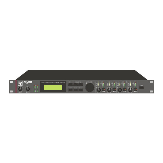
Page 5: Controls And Connections
1, Control INPUT 1 / INPUT 2 Rotary controls to set the input levels of the inputs 1 and 2 of the Dx 38. The input signal can be amplified by up to 6 dB (control set to its clockwise margin) or attenuated by any degree. - Page 6 11, OUTPUT-controls 1 - 4 These rotary controls are used to set the output levels of channels 1 to 4, allowing to match the Dx 38 to the input levels of the devices chained in sequence. Correctly setting these controls results in an improved S/N ratio.
-
Page 7: Rear Panel
These are the 2 balanced inputs of the Dx 38. Each input employs a Direct Out connector which allows to feed the unaltered input signal to another Dx 38 or to any other device that needs to be operated with the unaltered source signal. -
Page 8: Installation And Connections
European standard mains cord to the Dx 38 and your mains wall outlet. The power supply unit of the Dx 38 automatically adapts to supply voltages in a range of 90 to 250 VAC, so that the appliance can be operated with different, country-specific mains voltages. -
Page 10: Level Settings
CHANGING PARAMETERS Upon switching on the Dx 38, it always starts up in the NO EDIT mode; e. g. parameter changes are not possible. You have to enter NORMAL or FULL EDIT mode to be able to edit parameters (see also chapter 9.8, OPERATION MODE SELECTION). - Page 11 LOUDSPEAKER EQUALIZATION The Dx 38 embodies 4 EQs per channel for each output channel allowing to optimally match the frequency response for the connected loudspeaker components; similar to the factory preset programs. In case you want to program the EQs matching your own set of loudspeaker systems, you should know the exact frequency response of each component to be able to utilize the channel EQs efficiently.
- Page 12 Pressing another OUTPUT control selects the control’s corresponding output channel. MATCHING THE FREQUENCY RESPONSE Using the Master EQs in the input channels of the Dx 38, the PA-system can be easily matched to various environmental and acoustical conditions. In many cases, a graphic equalizer which normally is employed to perform this task is not needed any longer.
-
Page 13: Configurations Of The Dx 38
If you do not want to use one of the pre-defined configurations, you have also the possibility to operate the Dx 38 in Full Edit mode. This mode offers access to all parameters and basically any input/output routing can be programmed. Additionally, the output assignment (output function - Sub, Lo, Mid, Hi, Fullrange) is also freely definable. - Page 14 CONFIGURATIONS OF THE Dx 38 6.1 Stereo 2 Way This configuration generally represents a 2-way stereo frequency crossover, where IN 1 serves as the left input channel and IN 2 as the right input channel. OUT 1 is the left Low-range output and OUT 2 is the left High-range output.
-
Page 15: Way + Fullrange
CONFIGURATIONS OF THE Dx 38 6.3 3 Way + Fullrange The 3-Way + Fullrange configuration is a 3-way monaural x-over with additional full range output where IN 1 serves as input channel. OUT 1 is the Sub-range channel, OUT 2 the Mid-range channel, OUT 3 the High-range channel, and OUT 4 is the Fullrange channel. -
Page 16: Way / Independent Sub + Fullrange
CONFIGURATIONS OF THE Dx 38 6.5 3 Way / Independent Sub + Fullrange As well as the two previous configurations, this configuration also represents a 3-way frequency crossover with additional full range output, with the difference that the Sub-range channel OUT 1 gets its signal-feed from the input channel IN 2. - Page 17 CONFIGURATIONS OF THE Dx 38 6.7 2-IN-4 In this configuration, all 4 outputs are configured for full range operation. OUT 1 and OUT 2 get their signal-feed from the input channel IN 1 while OUT 3 and OUT 4 are fed from the input channel IN 2. This structure is suitable for instance for the equalization of full range (wide-band) loudspeaker systems or passive multi-way systems.
-
Page 18: Operation
The rotary encoder with push-button function for fast editing of parameter values, 6 function keys, and the push-button function of the output level controls OUT 1 - 4 are the main controls of the Dx 38. With EDIT, OPTION, STORE and RECALL you are able to branch off to and also return from the corresponding menus. -
Page 19: Program Selection
OPERATION 7.1 PROGRAM SELECTION The Dx 38 offers 30 user-definable program presets (U01 - U30) and up to 50 factory pre-programmed presets (F01-F50). Altogether you have the possibility to choose from this selection of up to 80 different programs. CAUTION: A program also defines the configuration and therefore also assignment of the inputs and outputs of the Dx 38. - Page 20 OPERATION 3. Whenever the function block in the first line is selected, you are able to select another function block by using the rotary encoder (10). Pressing one of the controls OUT 1 - 4 lets you directly select the function blocks of the corresponding output channel.
-
Page 21: Store Programs And Program Names
OPERATION 7.3 STORE PROGRAMS AND PROGRAM NAMES Whether you want to store an edited program, alter the name of a program, or copy a program from one preset location to another - in all cases the necessary procedure is the same. Pressing the STORE key (8) always starts and executes the saving procedure. -
Page 22: Modifying Factory-Preset-Programs
7.4 MODIFYING FACTORY PRESET PROGRAMS The easiest and quickest way to achieve good results with the Dx 38 is the use of a factory preset program. Factory preset programs are carefully designed, factory-pre-set programs that are stored non-volatile in the FLASH memory of the Dx 38. -
Page 23: Parameters
PARAMETERS 8. PARAMETERS Depending on its configuration and operation mode, the Dx 38 offers a selection of more or less different parameters. The parameters are assigned to the input channels IN1, IN2, IN1+2 and to the 4 output channels OUT1, OUT2, OUT3, OUT4. The channel number is indicated in the top left corner of the display while the function block (MASTER EQ, MASTER DELAY, CHANNEL EQ, etc.) is shown next to the... -
Page 24: Parameter Access
PARAMETERS 8.1 PARAMETER ACCESS Depending on the actual configuration, only certain parameters are relevant. To provide a better overview and prevent erroneous operation, in the STANDARD Edit mode only those parameters are accessible. Additionally and to further improve operational comfort, corresponding parameters are linked. For Instance, in the Stereo 2-Way configuration, the Master EQs, the Master delays, the outputs OUT1 / OUT3 and OUT2 / OUT4, and the X-Over parameters are linked for mutual setting. -
Page 25: Parameter Link-Table
MASTER EQ1-5 Both input channels of the Dx 38 employ a 5-Band parametric EQ, each, which provide extreme flexibility in the programming of full range equalization to match the sound reinforcement system to different acoustic conditions and venues which in most cases makes the need for post-mix graphic equalization unnecessary. - Page 26 B6-alignment; i. e. an increase in the response in the cutoff frequency range. The following examples are meant to show you the effect of different parameter settings. The Dx 38 editor software allows you to make your own adjustments via PC or notebook computer and monitor the resulting frequency response on the computer screen.
- Page 27 PARAMETERS PEQ: f = 1kHz, Gain = -12dB Q = 0.5, 1.0, 5.0, 20.0 Low Shelving Filter (LOSLV): f = 200Hz, Slope = 6dB Gain = +3dB, +6dB, +9dB, +12dB High Shelving Filter (HISLV): f = 2000Hz, Slope = 6dB Gain = +3dB, +6dB, +9dB, +12dB Low Shelving Filter (LOSLV): f = 200Hz, Slope = 12dB,...
- Page 28 ROUTING Any combination of input channels can be assigned to the outputs of the Dx 38. The routing defines which input signal is fed to either one of the output channels (OUT1, OUT2, OUT3, OUT4). Besides routing the signals of the two input channels IN1 and IN2 to one of the outputs, it is also possible to assign the summed, monaural audio signal of both inputs IN1+2 to one of the outputs.
- Page 29 PARAMETERS CHANNEL EQ1-4 The four output channels of the Dx 38 employ a 4-band parametric EQ each which allow to program additional equalization for the individual frequency ranges. This guarantees the optimum frequency response that is matched to the connected loudspeaker components.
- Page 30 Examples for the settings of different filter types are provided in the paragraph MASTER EQ1-5. You are also able to program your own settings of the Dx 38 via PC or notebook computer and monitor the resulting frequency response on the computer screen. The following example shows the phase response of Allpass filters with different parameter settings.
- Page 31 PARAMETERS HIPASS X-OVER The frequency crossover filter consists of a low pass filter in one channel and a high pass filter in the adjacent channel. Here, the frequency x-over filter’s Hi-Pass parameters are set. The parameters of the corresponding Lo-Pass should be set to the same values. An x-over filter provides the parameters “Type” and “f”.
- Page 32 PARAMETERS The f parameter (frequency) sets the x-over Lo-Pass filter’s cutoff frequency. The corresponding Hi-Pass filter should be set to the same cutoff frequency. Pol defines the polarity of the corresponding channel. Depending on the characteristic of the frequency crossover filter, inverting the polarity of a channel’s signal may become necessary; i. e.: set a negative polarity.
- Page 33 PARAMETERS CHANNEL DELAY These delays are provided in the output channels OUT1 - OUT4. They are used to compensate differences in loudspeaker dispersion plains that can be cabinet imminent or result from the positioning of individual loudspeaker cabinets or arrays. The delay time or acoustical distance is displayed in milliseconds, microseconds, feet, inches, meters, or centimeters.
- Page 34 PARAMETERS COMPRESSOR The compressor automatically reduces level peaks above a certain threshold and therefore provides reliable protection against power amplifier clipping and damaging the connected loudspeaker systems. Parameter Settings / Value range Default Thrsh 0.27V - 8.70V 8.70V 1/1.0, 1/1.4, 1/2.0, 1/4.0, 1/8.0 1/2.0 Attack 0ms - 99ms...
- Page 35 PARAMETERS LIMITER The limiter provides additional protection against the occurrence of clipping and overload conditions. The maximum level of the audio signal is limited to the set threshold value. The short attack times guarantee that even sudden peak levels are effectively attenuated. Parameter Settings / Value range Default...
-
Page 36: Option-Functions
OPTION 9. OPTION FUNCTIONS The “option programs” offer several additional, important information and preference settings for the Dx 38. Using the SELECT keys you can choose between the following functions: - LCD CONTRAST setting - COMPR & LIMIT THRESH UNIT - setting of the compressor’s and limiter’s threshold unit... -
Page 37: Vu Level Meter Display Mode
STORE key. When trying to change one of the appliance’s settings, SYSTEM IS LOCKED! appears on the display, indicating that the Dx 38’s operating system is blocked for entries via the numeric keys or the rotary encoder. To disable edit-protection, select the “LOCK CODE” page in the OPTION mode again. The display shows: Enter the correct password code number and press STORE to acknowledge the entry. -
Page 38: Operation Mode Selection
OPTION 9.5 OPERATION MODE SELECTION This page allows you to choose the operation mode which the Dx 38 is operated in. The display shows the following selection menu: When you select NO EDIT, editing and program selection is not possible. After switching on the Dx 38 is always in NO EDIT MODE. -
Page 39: Specifications
SPECIFICATIONS 10. SPECIFICATIONS 10.1 TECHNICAL SPECIFICATIONS Mains voltage 90 - 250 V AC / 50 - 60 Hz Power consumption 20 watts Safety class Inputs 2 x XLR IN, electronically balanced, transformer optional available 2 x XLR OUT (Direct Out) Input voltage (nominal) 1.55 V / + 6 dBu Max. -
Page 40: Retrofitting Instructions
1 x Screw M2,5 x 6 Installation instructions NRS 90244: 1. Switch the Dx 38’s power off and unplug the mains cord. 2. Remove the cover plate after unscrewing 2 screws on the top, 4 on the sides, and 3 on the rear. -
Page 41: Installation Manuals For Interface Cards
The newly installed interface is automatically recognized. 8. Now, you are able to make all necessary software settings for the interface in the OPTION mode (see also chapter 9, OPTION FUNCTIONS). Position of the NRS 90243, NRS 90246, NRS 90247 in the Dx 38 10-3... -
Page 42: Block Diagram
BLOCKDIAGRAMM 10-4... -
Page 43: Dimensions
ABMESSUNGEN / DIMENSIONS Abmessungen / Dimensions (in mm) 10-6...
Need help?
Do you have a question about the Dx 38 and is the answer not in the manual?
Questions and answers