Electro-Voice Dx38 Owner's Manual
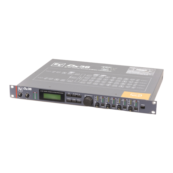
24 bit digital sound system processor
Hide thumbs
Also See for Dx38:
- Service manual (44 pages) ,
- Owner's manual (43 pages) ,
- Specifications (8 pages)
Table of Contents
Advertisement
Advertisement
Table of Contents

Related Manuals for Electro-Voice Dx38


Summary of Contents for Electro-Voice Dx38
- Page 1 OWNER’S MANUAL Dx 38 24 BIT DIGITAL SOUND SYSTEM PROCESSOR...
-
Page 2: Important Safety Instructions
IMPORTANT SAFETY INSTRUCTIONS Read these instructions. Keep these instructions. Heed all warnings. Follow all instructions. Do not use this apparatus near water. Clean only with a damp cloth. Do not block any of the ventilation openings. Install in accordance with the manufactures instructions. Do not install near any heat sources such as radiators, heat registers, stoves, or other apparatus that produce heat. -
Page 3: Table Of Contents
TABLE OF CONTENTS SAFETY AND SERVICE INSTRUCTIONS ........1-2 1. -
Page 4: Introduction
Providing 48-bit filter algorithms, 24-bit AD/DA conversion and a dynamic range of 115 dB, the Dx 38 sets new standards for digital loudspeaker controllers and processors. The Dx 38 is an universal Digital Sound System Processor that provides 2 inputs and 4 outputs; plus internal summing of the inputs 1 and 2. Via matrix it is possible to assign the outputs to any input or to the sum of the inputs. -
Page 5: Controls And Connections
C O N T R O L S A N D C O N N E C T I O N S 2. CONTROLS AND CONNECTIONS 2.1 FRONT PANEL 1, Control INPUT 1 / INPUT 2 Rotary controls to set the input levels of the inputs 1 and 2 of the Dx 38. The input signal can be amplified by up to 6 dB (control set to its clockwise margin) or attenuated by any degree. - Page 6 C O N T R O L S A N D C O N N E C T I O N S 8, STORE-key This key allows the user to store edited programs in one of the user-definable program presets (U01 - U30) or to copy programs from one preset to another.
-
Page 7: Rear Panel
C O N T R O L S A N D C O N N E C T I O N S 2.2 REAR PANEL 17, Mains connector Connect the supplied mains cord to the mains connector. The Dx 38 is capable of handling mains voltages between 90 V AC to 250 V AC, so that switching the mains on the appliance is not necessary. -
Page 8: Installation And Connections
I N S T A L L A T I O N A N D C O N N E C T I O N S 3. INSTALLATION AND CONNECTIONS Correct connections is a vital factor in achieving the best results with the Dx 38. Before switching on the power you have to connect the supplied European standard mains cord to the Dx 38 and your mains wall outlet. -
Page 9: First Operation
F I R S T O P E R A T I O N 4. FIRST OPERATION 4.1 SWITCHING THE POWER ON Using the POWER-switch (16) the Dx 38’s power is switched on. Upon initializing is complete, the last program that had been active before turning off the appliance is recalled. For now, the display shows: Now, the Dx 38 is ready for operation. -
Page 10: Quick Start
Q U I C K S T A R T 5. QUICK START This paragraph describes in an overview the most important steps for a trouble-free operation of the Dx 38 in your PA-system. For a more detailed description of specific functions and parameters, please refer to the corresponding paragraph in the handbook. - Page 11 X-OVER SETTINGS In the Edit menu select the desired output channel by pressing the corresponding OUTPUT control. Then use the rotary encoder to select HIPASS XOVER in the display. Here you can set the low-cut frequency for the selected channel. Using the SELECT keys, you are able to select the parameters “Type” or “f” and edit their values through the use of the rotary encoder.
- Page 12 Q U I C K S T A R T COMPRESSOR / LIMITER SETTINGS A compressor / limiter automatically reduces level peaks above a certain threshold and therefore provides reliable protection against power amplifier clipping and damaging the connected loudspeaker systems. In most cases it is absolutely sufficient to set the compressor’s threshold to the modulation limit of the connected power amplifier.
-
Page 13: Configurations Of The Dx 38
6. CONFIGURATIONS OF THE Dx 38 The Dx 38 offers 7 pre-defined configurations. A configuration is a basic setting that includes the routing of inputs and outputs, the function of the outputs (Sub, Lo, Mid, Hi, Fullrange), as well as the kind and amount of parameters. -
Page 14: Stereo 2 Way
C O N F I G U R A T I O N S O F T H E D x 3 8 6.1 Stereo 2 Way This configuration generally represents a 2-way stereo frequency crossover, where IN 1 serves as the left input channel and IN 2 as the right input channel. -
Page 15: Way + Fullrange
C O N F I G U R A T I O N S O F T H E D x 3 8 6.3 3 Way + Fullrange The 3-Way + Fullrange configuration is a 3-way monaural x-over with additional full range output where IN 1 serves as input channel. -
Page 16: In-4
C O N F I G U R A T I O N S O F T H E D x 3 8 6.5 3 Way / Independent Sub + Fullrange As well as the two previous configurations, this configuration also represents a 3-way frequency crossover with additional full range output, with the difference that the Sub-range channel OUT 1 gets its signal-feed from the input channel IN 2. - Page 17 C O N F I G U R A T I O N S O F T H E D x 3 8 6.7 2-IN-4 In this configuration, all 4 outputs are configured for full range operation. OUT 1 and OUT 2 get their signal-feed from the input channel IN 1 while OUT 3 and OUT 4 are fed from the input channel IN 2.
-
Page 18: Operation
O P E R A T I O N 7. OPERATION The rotary encoder with push-button function for fast editing of parameter values, 6 function keys, and the push-button function of the output level controls OUT 1 - 4 are the main controls of the Dx 38. With EDIT, OPTION, STORE and RECALL you are able to branch off to and also return from the corresponding menus. -
Page 19: Program Selection
7.1 PROGRAM SELECTION The Dx 38 offers 30 user-definable program presets (U01 - U30) and up to 50 factory pre-programmed presets (F01-F50). Altogether you have the possibility to choose from this selection of up to 80 different programs. CAUTION: A program also defines the configuration and therefore also assignment of the inputs and outputs of the Dx 38. - Page 20 O P E R A T I O N 3. Whenever the function block in the first line is selected, you are able to select another function block by using the rotary encoder (10). Pressing one of the controls OUT 1 - 4 lets you directly select the function blocks of the corresponding output channel.
-
Page 21: Store Programs And Program Names
7.3 STORE PROGRAMS AND PROGRAM NAMES Whether you want to store an edited program, alter the name of a program, or copy a program from one preset location to another - in all cases the necessary procedure is the same. Pressing the STORE key (8) always starts and executes the saving procedure. -
Page 22: Modifying Factory-Preset-Programs
O P E R A T I O N CAUTION! The program that was previously stored in this preset location is being erased! Please make sure, that the selected destination program number matches the number you want to save the program under. Pressing any other key cancels the saving procedure. After saving is complete, the Store menu is automatically quitted and the display might look for instance like this: 7.4 MODIFYING FACTORY PRESET PROGRAMS... -
Page 23: Parameters
8. PARAMETERS Depending on its configuration and operation mode, the Dx 38 offers a selection of more or less different parameters. The parameters are assigned to the input channels IN1, IN2, IN1+2 and to the 4 output channels OUT1, OUT2, OUT3, OUT4. The channel number is indicated in the top left corner of the display while the function block (MASTER EQ, MASTER DELAY, CHANNEL EQ, etc.) is shown next to the channel number. -
Page 24: Parameter Access
P A R A M E T E R S 8.1 PARAMETER ACCESS Depending on the actual configuration, only certain parameters are relevant. To provide a better overview and prevent erroneous operation, in the STANDARD Edit mode only those parameters are accessible. Additionally and to further improve operational comfort, corresponding parameters are linked. -
Page 25: Parameter Link-Table
8.1.2 PARAMETER LINK-TABLE Stereo 2 Way / Stereo Mono 2 Way Sub + Fullrange IN1 / IN2 EQ IN1 / IN2 Delay Y E S IN1 / IN2 / IN1+2 Delay OUT1 / OUT3 Y E S OUT2 / OUT4 OUT2 / OUT3 YES: Parameters are linked Parameters are not linked... - Page 26 P A R A M E T E R S Type describes the selected filter type. When selecting BYPASS, no effect is applied. PEQ provides a parametric Peak Dip Filter with programmable frequency, quality, and gain. LOSLV / HISLV stand for Low Shelving or High Shelving Equalizer, respectively.
- Page 27 PEQ: f = 1kHz, Gain = -12dB Low Shelving Filter (LOSLV): High Shelving Filter (HISLV): Low Shelving Filter (LOSLV): High Shelving Filter (HISLV): Hi-Pass Filter (HIPASS):f = 100Hz, Slope = 6dB, 12dB Q = 0.7, 1.0, 2.0 Lo-Pass Filter (LOPASS):f = 5000Hz, Slope = 6dB, 12dB Q = 0.7, 1.0, 2. Q = 0.5, 1.0, 5.0, 20.0 f = 200Hz, Slope = 6dB f = 2000Hz, Slope = 6dB...
-
Page 28: Master Delay
P A R A M E T E R S MASTER DELAY These delay lines are located in the inputs IN1, IN2 and in the summed input signal IN1+2; all x-over channels are affected. For instance, this allows to feed different PA-towers at open air concerts with delayed signals. The delay times are displayed in milliseconds and microseconds while the equivalent distances (unit) are displayed in feet, inches, meters or centimeters. - Page 29 CHANNEL EQ1-4 The four output channels of the Dx 38 employ a 4-band parametric EQ each which allow to program additional equalization for the individual frequency ranges. This guarantees the optimum frequency response that is matched to the connected loudspeaker components. Parameter Type Gain...
- Page 30 P A R A M E T E R S Gain sets the degree of amplification or attenuation of the parametric EQ or the low shelving and high shelving equalizers. The setting is performed in steps with 1 dB-stepwidth. The Slope parameter describes the steepness or order of the filter for the low shelving or high shelving equalizers.
- Page 31 HIPASS X-OVER The frequency crossover filter consists of a low pass filter in one channel and a high pass filter in the adjacent channel. Here, the frequency x-over filter’s Hi-Pass parameters are set. The parameters of the corresponding Lo-Pass should be set to the same values. An x-over filter provides the parameters “Type” and “f”.
- Page 32 P A R A M E T E R S The f parameter (frequency) sets the x-over Lo-Pass filter’s cutoff frequency. The corresponding Hi-Pass filter should be set to the same cutoff frequency. Pol defines the polarity of the corresponding channel. Depending on the characteristic of the frequency crossover filter, inverting the polarity of a channel’s signal may become necessary;...
-
Page 33: Channel Delay
CHANNEL DELAY These delays are provided in the output channels OUT1 - OUT4. They are used to compensate differences in loudspeaker dispersion plains that can be cabinet imminent or result from the positioning of individual loudspeaker cabinets or arrays. The delay time or acoustical distance is displayed in milliseconds, microseconds, feet, inches, meters, or centimeters. - Page 34 P A R A M E T E R S COMPRESSOR The compressor automatically reduces level peaks above a certain threshold and therefore provides reliable protection against power amplifier clipping and damaging the connected loudspeaker systems. Parameter Thrsh 0.27V - 8.70V 1/1.0, 1/1.4, 1/2.0, 1/4.0, 1/8.0 Attack 0ms - 99ms...
- Page 35 LIMITER The limiter provides additional protection against the occurrence of clipping and overload conditions. The maximum level of the audio signal is limited to the set threshold value. The short attack times guarantee that even sudden peak levels are effectively attenuated. Parameter Thrsh 0.27V - 8.70V...
-
Page 36: Option-Functions
O P T I O N 9. OPTION FUNCTIONS The “option programs” offer several additional, important information and preference settings for the Dx 38. Using the SELECT keys you can choose between the following functions: - LCD CONTRAST setting - EDIT MODE selection - COMPR &... -
Page 37: Compressor And Limiter Threshold Unit
O P T I O N 9.3 COMPRESSOR AND LIMITER THRESHOLD UNIT This function allows setting the unit of the compressor and limiter threshold. Volts: The threshold value is displayed in volts. dBu (0.775 V): The threshold value is displayed in dBu (0dBu = 0.775V). dB from Clip: Threshold setting in dB relative to full modulation. -
Page 38: Temperature Unit Settings
O P T I O N The following safety dialog appears: ARE YOU SURE? PRESS STORE TO CONFIRM ! Press the STORE twice to acknowledge this dialog. When trying to change one of the appliance’s settings, SYSTEM IS LOCKED! appears on the display, indicating that the Dx 38’s operating system is blocked for entries via the numeric keys or the rotary encoder. -
Page 39: Send Parameters
O P T I O N You can select one of the following settings for the MIDI TX CHANNEL: Off: No MIDI DATA is transmitted. 1 - 16: The Dx 38 transmits MIDI DATA via the selected MIDI channel 1 to 16. 9.8 SEND PARAMETERS During editing or when sending a program change command, the Dx 38 is capable of transmitting its parameters in real time via the serial port(s). -
Page 40: Nrs 90246 Contact Closure Interface Settings
O P T I O N Off: No RS-232 data is transmitted via MIDI ports. Data that is received from the RS-232 port is passed on to linked units via the MIDI port and is transmitted using the previously selected MIDI transmission channel (MIDI TX CHANNEL). 9.10 NRS 90246 CONTACT CLOSURE INTERFACE settings Amongst others, the Dx 38 is prepared for retrofitting an optional NRS 90246 Contact Closure Interface, which can be used instead of the RS-232 interface. -
Page 41: Nrs 90247 Rs-485 Interface Settings
RS-232 interface is possible as well. The RS-485 interface allows configuring, controlling and monitoring up to 31 Dx38 from a PC. In that case, assigning individual RS-485 IDs to each Dx38 is necessary. The Group-ID can only be edited via the PC-software. RS-485 IDs are set in the following menu. -
Page 42: Specifications
SPECIFICATIONS 10. SPECIFICATIONS 10.1 TECHNICAL SPECIFICATIONS Mains voltage Power consumption Safety class Inputs Input voltage (nominal) Max. input voltage Input impedance Common mode rejection AD-conversion Outputs Output voltage (nominal) Max. output voltage Output impedance Min. load impedance DA-conversion Frequency response S/N ratio Distortion without transformer Distortion with transformer... -
Page 43: Midi
10.2 MIDI This chapter provides information (all implemented MIDI transmission commands) for the experienced software programmer that wants to design new software for the Dx 38. The implementation chart is relevant for the software revision V1.0 or higher. MIDI data transfer is possible, only when a MIDI channel is activated (OMNI, 1 - 16). See also chapter 9.7, MIDI RX / TX CHANNEL settings. - Page 44 M IDI Serial Link MIDI-Byte (recognized + transmitted) F0 (hex) 00,00 DATA CHECKS Further details concerning the Command Parser ASCII Code are shown in the following tables. UNIT-ID /ID1/ COMMAND/ DEVICE ? COMCONF LINEFEED PROMPT ECHO Ddescription System Exclusive Extended ID (two bytes) Electro-Voice ID: No 118 n = MIDI Channel 0 - 15 (7F = All Channels) Dx 38 ID: No 38...
- Page 45 UNIT-ID /ID1/ IN1/ IN2/ INSUM/ OUT1/ OUT2/ ... OUT4/ MISC/ DELAY_OUT_UNIT TEMPERATURE_UNIT THRESHOLD_UNIT /ID2/ ... /ID32/ For Type = Allpass: Slope = 6: First Order Allpass Slope = 12: Second Order Allpass Example: /ID3/ OUT1/ XOVER/ HIPASS/ FREQ 1500 C o m m a n d P a r s e r C o d e T a b l e Tree DELAY EQ1/...
-
Page 46: Retrofitting Instructions
R E T R O F I T T I N G I N S T R U C T I O N S 10.3 RETROFITTING INSTRUCTIONS CAUTION: These servicing instructions are for use by qualified personnel only. To reduce the risk of electric shock, do not perform any servicing other than that contained in the Operating Instructions unless you are qualified to do so. -
Page 47: Installation Manuals For Interface Cards
10.3.2 Installation manuals for interface cards: Contact Closure Interface RS-485 Interface Contents NRS 90246: 1 x Information sheet NRS 90246 1 x Printed board assembly Contact Closure (83114) 1 x Rear plate blinding 4 x Screws M3 x 6 Contents NRS 90247: 1 x Information sheet NRS 90247 1 x Information sheet “Important Information”... -
Page 48: Block Diagram
B L O C K D I A G R A M M / B L O C K D I A G R A M 10-7... -
Page 49: Flow Diagram
F L U S S D I A G R A M M / F L O W D I A G R A M 10-5... -
Page 50: Dimensions
A B M E S S U N G E N / D I M E N S I O N S Abmessungen / Dimensions (in mm) 10-6... -
Page 51: Warranty
WARRANTY (Limited) Electro-Voice products are guaranteed against malfunction due to defects in materials or workmanship for a specified period, as noted in the individual product-line statement(s) below, or in the individual product data sheet or owner’s manual, beginning with the date of original purchase. If such malfunction occurs during the specified period, the product will be repaired or replaced (at our option) without charge.
Need help?
Do you have a question about the Dx38 and is the answer not in the manual?
Questions and answers