Table of Contents
Advertisement
Advertisement
Table of Contents

Related Manuals for Audio enhancement CAE-20W

Summary of Contents for Audio enhancement CAE-20W
- Page 1 Product Instruction Manual...
-
Page 2: Table Of Contents
Table of Contents Introduction………………………………………………. Page 4-5 CE Declaration…………………………………………… Page 6-7 Safety Instructions………………………………………. Page 8-9 Explanation of Symbols…………………………………. Page 10 Achiever Operating Controls……………………………. Page 11-12 Ultimate II Operating Controls………………………….. Page 13-14 Ultimate IISE Operating Controls………………………. Page 15-17 Innovator Operating Controls…………………………… Page 18-19 Receiver RC-07 Operating Controls…………………….. - Page 3 Table of Contents Repair Form ……………………………………………. Page 58 Power Cords for EU……………………………………. Page 59-60 Safety Instructions for EU……………………………… Page 61 WEEE Fitting…...………………………………………. Page 62 Warranty…………………………………………………. Page 63...
-
Page 4: Introduction
Introduction AUDIO ENHANCEMENT has been creating technologically ad- vanced products that exceed expectations for over 25 years. They are designed by caring professionals for those who teach and those who will become the future leaders of America. Se- lecting the infrared classroom sound amplification system is the most important step to improve the learning environment. - Page 5 Introduction When asked to rank the importance of nine different types of equipment used in classroom instruction, of the teachers in general education ranked class- room amplification most important , even over the overhead projector, which came in second at 18% and the computer at 16%! (1) of the school day is spent by children engaged in listening activities.
-
Page 6: Ce Declaration
CE Declaration English We declare under our sole responsibility that the product to which this declara- tion relates is in conformity with the standards or other normative documents following the provisions of Directives 2006/95/EC and 2004/108/EC. German Wir erklären in alleiniger Verantwortung, daß das Produkt, auf das sich diese Erklärung bezieht, mit der folgenden Normen oder normativen Dokumenten übereinstimmt. - Page 7 CE Declaration Swedish Vi deklarerar härmed värt fulla ansvar för att den produkt till vilken denna deklaration hänvisar är i överensstämmelse med standarddokument, eller andra normativa dokument som framställs i direktiv nr. 2006/95/EC och 2004/108/ Finnish Ilmoitamme yksinomaisella vastuullamme, että tuote, jota tämä ilmoitus koskee, noudattaa seuraavia standardeja tai muita ohjeellisia asiakirjoja, jotka noudattavat direktiivien 2006/95/EC ja 2004/108/EC säädöksiä.
-
Page 8: Safety Instructions
Safety Instructions 1) Read these instructions. 2) Keep these instructions. 3) Heed all warnings. 4) Follow all instructions. 5) Do not use this apparatus near water. 6) Clean only with dry cloth. 7) Do not block any ventilation openings. Install in accordance with the manufacturer‘s instructions. - Page 9 The connections should comply with local electrical code. • When the equipment is not used, make sure to contact your dealer and remove it. CAUTION: Before attempting to connect or operate this product, please read the label on the bottom (CAE-20W).
-
Page 10: Explanation Of Symbols
Explanation of Symbols Explanation of Symbols 220 - 240 Vac. A.C. Power Only 50 to 60 Hz Rated Mains Frequency The date or a dating code not exceeding any three consecutive months of manufacture. The dating code shall be in an established alphanumeric code affirmed by the manufacturer. -
Page 11: Achiever Operating Controls
ACHIEVER Operating Controls Front View (1)Power switch. Turns the power on/off. (2) Power indicator. Lights "green" when the power is turned ON. (3) Infrared Microphone Volume Control [ Teacher 1 and 2 ]. This control is used to adjust the level of the infrared microphones. (4) Infrared Signal Indicator [ Teacher 1 and 2]. - Page 12 ACHIEVER Operating Controls Rear View (9) DC power terminal. The AC adapter provided supplies 24 V DC power. (10) Sensor input terminal. Connection via F-connector and coaxial cable for the infrared sensors. It also supplies power to the sensors (24 V). (11) Input terminal [TV/DVD, CD/MP3].
-
Page 13: Ultimate Ii Operating Controls
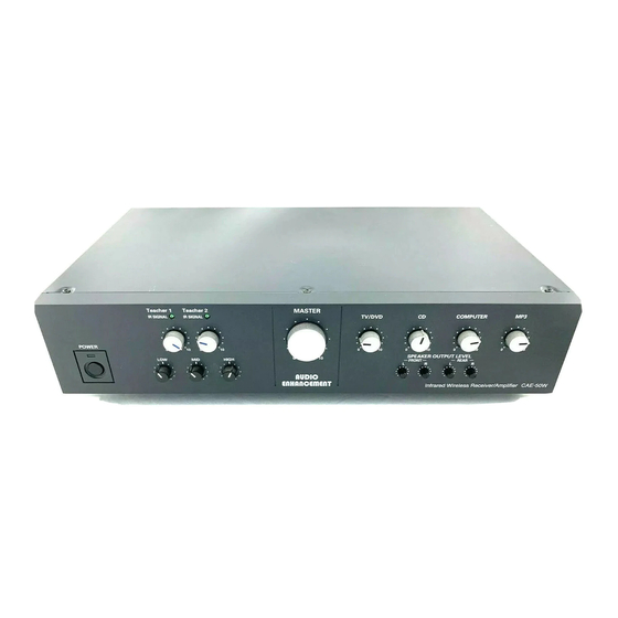
ULTIMATE II Operating Controls (1) Power switch. Turns the power on/off. (2) Power indicator. Lights "green" when the power is turned ON. (3) Infrared Microphone Volume Control [Teacher 1 and 2]. This control is used to ad- just the level of the infrared microphones. (4) Infrared Signal Indicator [Teacher 1 and 2]. - Page 14 ULTIMATE II Operating Controls (9) DC power terminal. The AC adapter provided supplies 24 V DC power. (10) Sensor input terminal. Connection via F-connector and coaxial cable for the infrared sensors. It also supplies power to the sensors (24 V). (11) Input terminal [TV/DVD, CD, COMPUTER, MP3].Connections for TV/DVD, CD, COMPUTER, and MP3.
-
Page 15: Ultimate Iise Operating Controls
ULTIMATE IISE Operating Controls (1) Power switch. Turns the power on/off. (2) Power indicator. Lights "green" when the power is turned ON. (3) Infrared Microphone Volume Control [Teacher 1 and 2]. This control is used to ad- just the level of the infrared microphones. (4) Infrared Signal Indicator [Teacher 1 and 2]. - Page 16 ULTIMATE IISE Rear Panel Connections (1) DC power supply terminal [24 V IN, 1.2 A] Connect the specified AC adaptor (accessory), and it supplies 24 V DC power. (2) Sensor input terminal [SENSOR INPUT 75Ω (3) Line input terminals - [LINE INPUT 1,2,3,4 –20dBV 10k Ohm] Connect exter- nal audio device (such as DVD etc).
- Page 17 ULTIMATE IISE “F” Function Setting the Function Channel on the Teacher microphone 1. Remove the battery cover of the microphone. Pull the battery cover in the arrow direction while pressing the “A” portion with both right and left thumbs to remove the cover.
-
Page 18: Innovator Operating Controls
INNOVATOR Operating Controls Front View (1) Power switch Turns the power on/off. (2) Power indicator Lights "green" when the power is turned ON. (3) Infrared Microphone Volume Control [Teacher 1 to 4] This control is used to adjust the level of the infrared microphones. (4) Infrared Signal Indicator [Teacher 1 to 4]... - Page 19 INNOVATOR Operating Controls Rear View 9) DC power terminal The AC adapter provided supplies 24 V DC power. (10) Sensor input terminal Connection via F-connector and coaxial cable for the infrared wireless sensors. It also supplies power to the sensors (24 V). (11) Input terminal [TV/DVD, CD, COMPUTER, MP3]...
-
Page 20: Receiver Rc-07 Operating Controls
RC-07 Infrared Receiver Operating Controls Front View (1) Power switch Turns the power on/off. (2) Power indicator Lights "green" when the power is turned ON. (3) Infrared Microphone Volume Control [Teacher 1 and 2] This control is used to adjust the level of the infrared microphones. (4) Infrared Signal Indicator [MIC 1 IR SIGNAL, MIC 2 IR SIGNAL]... - Page 21 RC-07 Infrared Receiver Operating Controls (9) DC power terminal The AC adapter provided supplies 24 V DC power. (10) Sensor input terminal Connection via F-connector and coaxial cable for the infrared sensors. It also supplies power to the sensors (24 V). (11)AUX input terminal Connections for TV/DVD, CD, COMPUTER, and MP3 etc.
-
Page 22: Student Microphone Operating Controls
STUDENT MICROPHONE Operating Controls (1A) Momentary power switch– Push to Talk. (1B) Continuous power switch– Slide up to lock on and then talk. (2) Power indicator –lights "green" when the power is turned either momentary or continuous. (3) Microphone (audio pickup) - speak into this part of the microphone. -
Page 23: Teacher Microphone Operating Controls
TEACHER MICROPHONE Operating Controls To change the battery: 1. Slide the rear cover(5) down towards the bottom of the microphone. 2. Replace battery with a standard “AA” NiMH rechargeable. Note: A standard “AA” Alkaline cell can be used on a temporary basis. Front View Rear View (1) Power/Mute switch: Turns the power on/off. -
Page 24: Charging The Battery In The Microphones
Charging the Microphone Battery 1. Plug the charger into the wall (1) to the AC mains. 2. Connect the charging plug(s) (3) to the microphone(s) 3. The red Charging LED (4) should come on and stay on during the charging proc- ess. -
Page 25: Solosolution Operating Controls
SoloSolution Operating Controls (1) Power switch. Turns the power on/off. (2) Power Indicator. Lights “amber” when the power is turned ON. (3) Infrared Microphone Volume Control [Teacher 1 and 2]. These controls are used to adjust the level of the Teacher/Student microphones. (4) Infrared Signal Indicator [Teacher 1 and 2]. -
Page 26: Eds-07 Ir Dome Sensor Operating Controls
EDS-07 IR SENSOR Operating Controls Rear View Front View (1) Infrared sensor cover Protects sensor and allows IR light to enter. – Power supplied by the receiver. (2) Sensor connection terminal Provides connection to the sensor input terminal of the infrared wireless receiver via F-connectors and coaxial cable. -
Page 27: Ae-Dcf Dome Sensor Coupler
AE-DCF Coupler Operating Controls Front View Rear View (1) Infrared Sensor Connections [F-connector] Connect Infrared Sensors via F-connector and coaxial cable. (2) Infrared Receiver Connection [F-connector] Mixed infrared sensor output provides signals from the vari- ous infrared sensors. Connect to the sensor input terminal of the infrared wireless receiver via F-connectors and coaxial cable. -
Page 28: Operating Procedure
Operating Procedure Example: Innovator Example: Student Microphone Example: Teacher Microphone 1. Turn the power switch on the receiver to “ON”. (2) The power indicator lights “green”. 2. Turn the power switch (7)on the infrared wireless microphone to “ON”. The power indicator (8) on the microphone lights “green”. 3. -
Page 29: Remote Volume Control
Using the Remote Volume Control Press to INCREASE the vol- Press the “SELECT” ume of the selected source. button until the blue LED is lit over the de- Press to DECREASE the sired source. volume of the selected source. The volume level of the infrared wireless microphones and the auxiliary inputs can be controlled from the teardrop infrared wireless transmitter. -
Page 30: Using The Microphones As A Transmitter
Using the Microphone as a Transmitter Teardrop Handheld (8) External input terminal on the side of the microphone. The infrared wireless microphone can be used as a transmitter by connecting a portable CD player or other device to the external input terminal. 1. -
Page 31: Setting The Aux Mute
Setting the Aux Mute ●Setting the Mute for the Audio Input of the Infrared Wireless Microphone Reduces the volume of the auxiliary inputs when the teacher speaks into the infrared wireless microphone. (11) Input terminal (13) AUX mute setting switch ●Set the "(13) AUX MUTE"... -
Page 32: Wiring Connections And Installation
Installation This connection diagram is an example of using 3 to 4 infrared wireless mi- crophones with the "Innovator" infrared receiver/amplifier. When using only two microphones, one of the “EDS-07”sensors and the “AE-DCF” mixer are not necessary. In that case, set the "frequency selector switch" on the sensor according to the microphone channels being used. - Page 33 Installation ■Connections ◎Remove the AC power cord from the power outlet when connecting the system. ◎Use the specified AC adapter. ●Basic Connections for the "Ultimate" ◎This connection diagram is an example of using 1 or 2 infrared wireless microphones with the "Ultimate II" infrared wireless receiver/amplifier. With this configuration set the "frequency selector switch"...
- Page 34 Installation ■Connections ◎Remove the AC power cord from the power outlet when connecting the system. ◎Use the specified AC adapter. ●Basic Connections for the "Achiever" ◎This connection diagram is an example of using 1 or 2 infrared wireless microphones with the "Achiever" infrared wireless receiver/amplifier. With this configuration set the "frequency selector switch"...
- Page 35 Installation ■Connections ◎Remove the AC power cord from the power outlet when connecting the sys- tem. ◎Use the specified AC adapter. ●Basic Connections for the "RC-07" ◎This connection diagram is an example of using 1 or 2 infrared wireless micro- phone with the "RC-07"...
- Page 36 Installation ●For Reception in Large Areas This connection diagram is an example using from 3 to 4 infrared wire- less microphones with the "Innovator“ receiver/amplifier. For reception in large ar- eas, add two "EDS-07" sensors as shown below. Up to 4 "EDS-07" sensors can be added to any receiver/amplifier. With this configuration, set all the "frequency selector switches"...
- Page 37 Installation Fix coaxial cable Coaxial cable Ceiling Sensor Floor ●Precautions for Installing the Sensors ◎Install the infrared sensors in a position that allows them to receive the infrared signal regardless of the teachers movement around the classroom. ◎Do not install the sensors in direct sunlight or directly in front of strong lighting fix- tures.
- Page 38 Installation ●Precautions for Installing the Sensors ・Install the infrared sensor in a position from which the screen of the plasma display cannot be seen, in other words, in the zone which is crosswise direction or behind from plasma display, and install the infrared sensor as far away as pos- sible (more than 10 meters) from the plasma display.
- Page 39 Installation Installation bracket Adjuster Ceiling panel Coaxial cable Anchor strap Installation screw ●Installing the Sensors: Part 1 Install the sensors as shown below if the coaxial cables have been routed through the ceiling and the ceiling panels can be removed. 1.
- Page 40 Installation Installation Bracket: Ceiling panel Installation- Diagram for bending bracket Coaxial cable Adjuster Anchor strap Screws Bend it according to the grooves. Installation screw ●Installing the Sensors: Part 2 If the coaxial cables cannot be routed through the ceiling, you can install the sensors as shown below if the ceiling panels cannot be removed.
- Page 41 Installation ●Range and Expansion of the Sensor Reception ◎One dome type infrared sensor has a practical range of approximately 24’. ◎Use the "AE-DCF" mixer to increase the number of sensors to cover a larger room. A total of four sensors can be added by using the "AE-DCF" Receiving from1ch/2ch(3ch/4ch) Approximately 24’...
- Page 42 Installation Coaxial Cables EDS-07 Coaxial cable :B Infrared sensor connector AE-DCF Coaxial cable : Coaxial cable :D INNOVATOR Coaxial cable :A Coaxial cable :E ●The following types and lengths of coaxial cables are recommended: Use the following lengths and types of coaxial cables to connect the main unit and the sensors.
-
Page 43: Eds-07 Dome Sensor Wiring And Placement
Installation Coaxial Cables Coaxial cable :B Infrared sensor connector AE-DCF Coaxial cable C Coaxial cable :D INNOVATOR Coaxial cable : A Coaxial cable: E ◎Part 1 [Good example] Coaxial cable length: If A = 120’, B = 24’, C = 12’, D = 18’, E = 30’ 【Results】... -
Page 44: Setting The Pa Aux Mute
Setting the PA Aux Mute (Continued from previous page) Auxiliary Input The mute function works as shown below: volume returns to original level after approximately 10 seconds Muting of auxiliary input Volume Auxiliary Input Level Auxiliary input Mute finished when levels reduced by inputs turned off 12 dB... - Page 45 Setting the PA Aux Mute (11) Auxiliary Inputs (15) PA input terminal (16) PA input volume PA hot signal PA cold signal ●Setting the Mute for the PA Input The Auxiliary Muting function reduces the volume of the audio signals that are coming into the auxiliary input terminals every time an announcement over the PA system is made.
- Page 46 Setting the EMG Aux Mute ●Setting the Emergency Mute Function The Emergency Mute Function (EMG) (17) allows selection of whether or not the audio level of the auxiliary inputs (11) is muted when a page is received from the PA system. (11) Input terminal (17) EMG input terminal...
-
Page 47: Setting The Emg Aux Mute
Setting the EMG Aux Mute (Continued from previous page) The mute function works as shown below: Auxiliary Input volume re- Volume Muting of auxiliary turns to original level after input starts approximately 2 seconds Auxiliary Input Level Auxiliary input levels reduced by Muting finished when 12 dB inputs turned off... -
Page 48: Fuse Part Numbers
About External Control The Audio levels of the "Innovator“ can be remotely controlled by connecting it to a personal computer via a serial port. The microphone levels can be controlled independ- ently, the auxiliary inputs are controlled as a single mixed signal. ●About connections Connect the "CAE-100W"... -
Page 49: Precautions For Installation
Precautions for Installation More Than More More 10 cm Than Than 10 10 cm Front side ● Precautions for Installing the Infrared Receiver and Infrared Receiver/Amplifier ◎Infrared Receiver and Infrared Receiver / Amplifier will produce small amounts of heat. Provide a minimum of 10 cm when installing the amplifier close to the ceiling or wall. Infrared Receiver and Infrared Receiver / Amplifier are for indoor use only. - Page 50 Installing the Bracket Installing MTBR-07L(STC-98014) for the Ultimate II and Innovator Receiver Amplifier Please carefully read the following assembly, installation and safety instructions before installation of MTBR-07L Bracket for Ultimate II and Innovator Receiver Amplifier. 1. Installation Surface – The enclosed accessories are suitable only for attaching to walls made of solid concrete or wood studs.
- Page 51 Installing the Bracket Installing the UltimateII and Innovator Receiver Amplifier on MTBR-07L Install the Ultimate II and Innovator Receiver/Amplifier as described below. 1. Fix the main unit to the bracket. Use 2 screws to fix the bracket to the side of main unit. 2.
- Page 52 Installing the Bracket Installing MTBR-07S(BT77) Bracket for Infrared Receiver RC-07 and Achiever Receiver/Amplifier Please carefully read the following assembly, installation and safety instructions before installation of MTBR-07S Bracket for Infrared Receiver RC-07 and Achiever Receiver/Amplifier. Installation Surface – The enclosed accessories are suitable only for attaching to walls made of solid concrete or wood studs.
-
Page 53: Installing The Bracket
Installing the Bracket ● The Infrared Receiver RC-07 and Achiever Receiver/Amplifier on MTBR-07S Install the Infrared Receiver RC-07 and Infrared Receiver / Amplifier Achiever as described below. 1. Fix the main unit to the bracket. Use 2 screws to fix the bracket to the side of main unit. The torque for the screws is 1.18 N・m±0.2 N・m (12 kgf・cm±2 kgf・cm) 2. -
Page 54: Fuse Part Numbers
TABLE: Part Number of Fuse Innovator Achiever RC-07 Ultimate II CAE-100W CAE-50W CAE-20W RC-07 F101 021806.3MX P 0218004.MX P 021802.5MXP 0218.315MXP F401 0218002.MX P 0218002.MX P 0218002.MXP F402 0218002.MX P 0218002.MX P 0218002.MXP F403 0218002.MX P 0218002.MX P F404 0218002.MX P 0218002.MX P F701 0218002.MX P... -
Page 55: Teachers Check List
Teacher’s Check List TURN on the transmitter (green LED will indicate power, red LED indicates that batteries need to be recharged). POWER on the amplifier (red LED will indicate power; green LED by teacher volume control indicates receipt of IR signal). TRANSMITTER/MICROPHONE needs to be worn in a way as to have a clear path to the receiving sensors. -
Page 56: Troubleshooting
Troubleshooting Transmitter is not working Is the battery light on your transmitter green? – Is the red light on your external sensor on? – Is there anything in the room blocking the sensor? – Move the obstruction and retry. If the problem is not fixed please contact Audio Enhancement. - Page 57 Troubleshooting No Audio Is your power supply plugged into the amplifier/receiver and the wall out- let? – Is the power switch set to “On” and the indicator light red? – Is the teacher transmitter turned on with a green battery light? –...
-
Page 58: Repair Form
Repair Form AUDIO ENHANCEMENT Ship Equipment to: Attn: Repairs 14241 S. Redwood Rd Please call for RMA# before returning PO Box 2000 product(s) Bluffdale, UT 84065 800-383-9362 RMA#____________ Repair Form Name:_______________________________________________ School/Company:______________________________________ Shipping Address:______________________________________ Attn:_________________________________________________ City/State/Zip:_________________________________________ Telephone: (____)______________________ Model #/Items Serial # &... -
Page 59: Power Cords For Eu
Power Cords for EU Innovator—CAE-100W Specified AC adapter PW-150A2-1Y-240E AC 220 - 240 V 50/60 Hz Ultimate II—CAE-100W Specified AC adapter 3A-901DA24-048 AC 220—240V 50/60 HZ Achiever—CAE-20W Receiver—RC-07 Specified AC adapter 3A-621DA24 AC 220—240V 50/60 HZ... - Page 60 This appliance is supplied with a moulded three pin mains plug for your safety and convenience. A 13 amp (CAE-100W) and 3 amp (CAE-50W, CAE-20W, RC-07) fuse is fitted in this mains plug. Shall the fuse need to be replaced, please ensure that the replacement fuse has a rating of 13 amp...
-
Page 61: Safety Instructions For Eu
Safety Instructions for EU The wire which is coloured green and yellow must be connected the terminal in the plug which is marked with the letter E or by the earth symbol or coloured green or green and yellow. The wire which is coloured blue must be connected to the terminal in the plug which marked with the letter N or coloured black. -
Page 62: Weee Fitting
WEEE Fitting Information on Disposal for Users of Waste Electrical & Electronic Equipment (private households) This symbol on the products and/or accompanying documents means that used electrical and electronic products should not be mixed with general household waste. For proper treatment, recovery and recycling, please take these products to designated collection points, where they will be ac- cepted on a free of charge basis. -
Page 63: Warranty
Standard 5-year Warranty Audio Enhancement (“Provider”) is pleased to offer a standard Five (5) year lim- ited manufacturers warranty (“Limited Warranty”) against malfunction due to manufacturing defects in materials or workmanship on the teardrop microphone, handheld microphone, receiver/amplifier systems, the external infrared sensors, and speakers (“Provider Products”).
Need help?
Do you have a question about the CAE-20W and is the answer not in the manual?
Questions and answers